Table of Contents
Advertisement
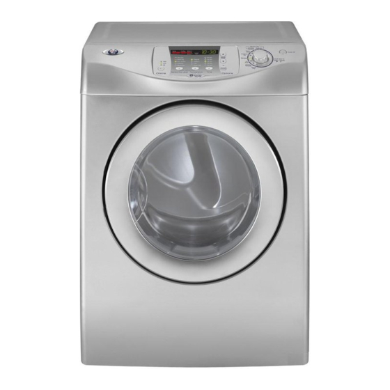
Service
This manual is to be used by qualified appliance
technicians only. Maytag does not assume any
responsibility for property damage or personal
injury for improper service procedures done by
an unqualified person.
27" Dryer
©2005 Maytag Services
This Base Manual covers general information
Refer to individual Technical Sheet
for information on specific models
This manual includes, but is
not limited to the following:
MDE9700A*
MDG9700A*
16025911
March 2005
Advertisement
Table of Contents

Related Manuals for Maytag MDE9700A Series


Summary of Contents for Maytag MDE9700A Series
- Page 1 Service This manual is to be used by qualified appliance technicians only. Maytag does not assume any responsibility for property damage or personal injury for improper service procedures done by an unqualified person. 27” Dryer This Base Manual covers general information...
-
Page 2: Important Information
Important Notices for Servicers and Consumers Maytag will not be responsible for personal injury or property damage from improper service procedures. Pride and workmanship go into every product to provide our customers with quality products. It is possible, however, that during its lifetime a product may require service. -
Page 3: Table Of Contents
Rear Bulkhead Removal ..........26 Rear Roller Removal ..........27 Gas Model Disassembly Procedures Igniter Removal ............27 Burner Removal ............28 Appendix A Installation Instructions ..........29 Appendix B Use And Care ............42 ©2005 Maytag Services 16025911 Rev. 0... -
Page 4: Important Safety Information
If they are 10. Do not tamper with dryer dried, wipe out the cylinder with a controls. damp cloth to remove particles of fiberglass. Save These Instructions 16025911 Rev. 0 ©2005 Maytag Services... - Page 5 (live) and the smaller slot is neutral. Grounded–This means the round hole connection is connected to ground through a connection to the main power panel. Ungrounded–The round hole connection is not connected to a ground and/or the main power panel. 16025911 Rev. 0 ©2005 Maytag Services...
- Page 6 MUST be exhausted to the outdoors. DO NOT exhaust dryer air into a window well, gas vent, chimney or enclosed, unventilated area, such as an attic, wall, ceiling, crawl space under a building or concealed space of a building. 16025911 Rev. 0 ©2005 Maytag Services...
- Page 7 Important Safety Information 16025911 Rev. 0 ©2005 Maytag Services...
-
Page 8: General Information
Complete registration card and promptly return. If registration card is missing: • For Maytag product call 1-800-462-9824 or visit the • For Maytag product call 1-800-688-9900 or visit the Web Site at www.maytag.com • For product in Canada call 1-866-587-2002 or visit the Web Site at www.maytag.com... -
Page 9: Model Nomenclature
Dryer Gas Canada 240V-60hz 220-240 V / 50-60 Hz Marketing Code Feature Content This identifies which 9700 Feature Package version of production the unit is. Troubleshooting Guide is Located on the back of the unit. 16025911 Rev. 0 ©2005 Maytag Services... -
Page 10: Troubleshooting Troubleshooting General Symptoms
• Clothes too wet due to insufficient spin out by • Hi-Limit trips easily or is open. washer. • Regulating thermostat trips easily or is open. • Membrane switch open. Will Not Shut Off • Check Thermistor. • Check Membrane Pad. 16025911 Rev. 0 ©2005 Maytag Services... -
Page 11: System Check Mode Table
Service Mode. Before advancing to the bar short, “0” for next test, the current test running must be terminated. sensor bar open Rotate the Cycle Selector View current cycle Knob to Time Dry temperature in Fahrenheit. ©2005 Maytag Services 16025911 Rev. 0... -
Page 12: Diagnostic Codes
Start/Pause button in the center of the Rotary Cycle Selector is pressed and held, the machine will display the number of cycles ago the diagnostic code occurred. When the Start/Pause button is released, the diagnostic code is again displayed. 16025911 Rev. 0 ©2005 Maytag Services... - Page 13 Door Open Running the Check for: dryer with - Close the door open door, and run the dryer - Loose or open wire terminals in Door Sense circuit. - Check for diagnostic code 3 ©2005 Maytag Services 16025911 Rev. 0...
-
Page 14: Component Testing Information
C 25A Check across terminals Less than 1 ohm Thermal Cut Off Unplug connectors and test Thermostat terminals. Check across terminals Less than 1 ohm Heater Element Unplug connectors and test Heater terminals 10 ohms 16025911 Rev. 0 ©2005 Maytag Services... - Page 15 (Holding Coil). 1350ohms Check across terminals #2 and #3 (Both coils in series). Check across 1900ohms terminals #4 and #5 (Secondary Coil). 1300ohms Motor Contacts Gas Valve Function Start = Contact closed Centrifugal Switch (Motor) ©2005 Maytag Services 16025911 Rev. 0...
-
Page 16: Disassembly Procedures
6. Remove Inner Panel. 3. Remove two screws attaching Door Hinge. 7. Remove Gasket. 4. Install Door and Strike on opposite sides or continue with Door disassembly. 5. Remove screws around perimeter of Door Inner Panel. 16025911 Rev. 0 ©2005 Maytag Services... -
Page 17: Interior Light
9. Remove outer door viewing panel. Insert screwdriver in slot to disengage latch. Top Removal 1. Disconnect power supply to unit. 2. Remove 2 10mm screws from dryer back. 3. Slide Top Cover towards the rear and lift from unit. 16025911 Rev. 0 ©2005 Maytag Services... -
Page 18: Drum Baffle Removal
4. Disconnect the black and white connectors. Drum Baffle Removal 1. Disconnect power supply to unit. 2. Remove Top Cover. 3. Remove four screws located at the sound dampening seem. 5. Remove four screws attaching Console to washer. 16025911 Rev. 0 ©2005 Maytag Services... -
Page 19: Front Panel Removal
6. Pull Front Panel forward and disconnect the Interior 3. Remove Console. Light harness. 4. Remove Front Cover. 5. Remove Heater Assembly retaining screw. 7. Lift the Front Panel off the three tabs across the bottom and remove. 16025911 Rev. 0 ©2005 Maytag Services... - Page 20 6. Slide Heater Assembly out the front of dryer.. 8. Reinstall by aligning the tabs on the back bulkhead with the notches in the Heater Assembly . 7. Remove the wiring terminals from the Heater Assembly. 16025911 Rev. 0 ©2005 Maytag Services...
-
Page 21: Front Bulkhead Removal
2. Remove Top Cover. 3. Remove Console. 4. Remove Front Panel. 5. Remove screws retaining Console Back Cover. 6. Disconnect Interior Light wiring harness. 8. Remove four Bulkhead retaining screws 7. Disconnect Moisture Sensor wiring harness. 16025911 Rev. 0 ©2005 Maytag Services... -
Page 22: Moisture Sensor Removal
4. Remove Front Panel. 5. Remove belt from Idler Pulley Moisture Sensor Removal 1. Disconnect power supply to unit. 2. Remove Top Cover. 3. Remove Console. 4. Remove Front Panel. 5. Disconnect Moisture Sensor wire harness. 16025911 Rev. 0 ©2005 Maytag Services... -
Page 23: Belt Switch Removal
5. Remove Console Back Cover. 6. Remove Belt from Idler Pulley. 7. Remove Drum. 8. Remove the two screws securing the Blower Intake Panel to the Blower Housing. Remove Blower Intake Panel. Belt Switch 16025911 Rev. 0 ©2005 Maytag Services... - Page 24 10.Remove the blower attachment screw under the Thermistor. 11. Remove two screws attaching the motor bracket to the base. 9. Removed the screw at the bottom of the blower housing. 16025911 Rev. 0 ©2005 Maytag Services...
- Page 25 15.Remove Blower Wheel. 14.Remove the 14mm nut securing the blower wheel to 16.Remove the three screws securing the blower the shaft. The nut is a left hand thread. housing to the motor bracket. 16025911 Rev. 0 ©2005 Maytag Services...
-
Page 26: Rear Bulkhead Removal
7. Remove Drum. 8. Remove 7 screws from the back. 18.Use a wide blade screwdriver to pop off the motor retention clamps. 9. Lift the rear bulkhead off the right and left side hangers. 16025911 Rev. 0 ©2005 Maytag Services... -
Page 27: Rear Roller Removal
1. Disconnect power supply to unit. 2. Remove Top Cover. 3. Remove Console. 4. Remove Front Panel. 5. Loosen the single screw attaching the igniter to the Burner Assembly. Slide the Igniter back and remove. 16025911 Rev. 0 ©2005 Maytag Services... -
Page 28: Burner Removal
3. Disconnect gas line. 5. Remove the two screws attaching the housing to the burner bracket. The screws are recessed from view. 6. Slide Burner Assembly from dryer. 4. Remove two screws securing burner to bracket. 16025911 Rev. 0 ©2005 Maytag Services... -
Page 29: Installation Instructions
A A A A A ppendix ppendix ppendix A A A A A ppendix ppendix 16025911 Rev. 0 ©2005 Maytag Services... - Page 30 16025911 Rev. 0 ©2005 Maytag Services...
- Page 31 16025911 Rev. 0 ©2005 Maytag Services...
- Page 32 16025911 Rev. 0 ©2005 Maytag Services...
- Page 33 16025911 Rev. 0 ©2005 Maytag Services...
- Page 34 16025911 Rev. 0 ©2005 Maytag Services...
- Page 35 16025911 Rev. 0 ©2005 Maytag Services...
- Page 36 16025911 Rev. 0 ©2005 Maytag Services...
- Page 37 16025911 Rev. 0 ©2005 Maytag Services...
- Page 38 16025911 Rev. 0 ©2005 Maytag Services...
- Page 39 16025911 Rev. 0 ©2005 Maytag Services...
- Page 40 16025911 Rev. 0 ©2005 Maytag Services...
- Page 41 16025911 Rev. 0 ©2005 Maytag Services...
-
Page 42: Appendix B Use And Care
A A A A A ppendix B ppendix B ppendix B ppendix B ppendix B 16025911 Rev. 0 ©2005 Maytag Services... - Page 43 16025911 Rev. 0 ©2005 Maytag Services...
- Page 44 16025911 Rev. 0 ©2005 Maytag Services...
- Page 45 16025911 Rev. 0 ©2005 Maytag Services...
- Page 46 16025911 Rev. 0 ©2005 Maytag Services...
- Page 47 16025911 Rev. 0 ©2005 Maytag Services...
- Page 48 16025911 Rev. 0 ©2005 Maytag Services...
- Page 49 16025911 Rev. 0 ©2005 Maytag Services...
- Page 50 16025911 Rev. 0 ©2005 Maytag Services...
- Page 51 16025911 Rev. 0 ©2005 Maytag Services...
- Page 52 16025911 Rev. 0 ©2005 Maytag Services...
- Page 53 16025911 Rev. 0 ©2005 Maytag Services...
- Page 54 16025911 Rev. 0 ©2005 Maytag Services...
- Page 55 16025911 Rev. 0 ©2005 Maytag Services...
- Page 56 16025911 Rev. 0 ©2005 Maytag Services...
- Page 57 16025911 Rev. 0 ©2005 Maytag Services...
- Page 58 16025911 Rev. 0 ©2005 Maytag Services...