Advertisement
Table of Contents
IMPORTANT NOTICE
. OPERATOR AND PASSENGER
This scooter is designed to carry the operator and one passenger. Never exceed
the vehicle capacity load as shown on the tire information label.
. ON-ROAD USE ONLY
This scooter is not equipped with a spark arrester and is designed to be used only
on the road. Operation in forest, brush or grass covered areas may be illegal.
Obey local laws and regulations.
. READ THIS OWNER'S MANUAL CAREFULLY
Pay special attention to statements preceded by the following words:
Indicates a strong possibility of severe personal injury or loss of life if instruc-
tions are not followed.
CAUTION
Indicates a possibility of personal injury or equipment t damage if instructions are
not followed.
NOTE: Gives helpful information.
This manual should be considered a permanent part of the scooter and should
remain with the scooter when resold.
Advertisement
Table of Contents

Related Manuals for Honda CH250 ELITE250


Summary of Contents for Honda CH250 ELITE250
- Page 1 IMPORTANT NOTICE . OPERATOR AND PASSENGER This scooter is designed to carry the operator and one passenger. Never exceed the vehicle capacity load as shown on the tire information label. . ON-ROAD USE ONLY This scooter is not equipped with a spark arrester and is designed to be used only on the road.
- Page 2 All information in this publication is based on the latest product information available at the time of approval for printing. HONDA MOTOR CO., LTD. reserves the right to make changes at any time without notice and without incurring any obligation.
- Page 3 Honda. These items include: * Honda Owner’s Identification Card * Set-up and Predelivery Checklist * Honda Motor Scooter Emission Control System, Distributor’s Warranty * Honda Motor Scooter, Distributor’s Limited Warranty * Honda Motor Scooter Noise Control Systems, Distributor’s Warranty.
-
Page 4: Table Of Contents
OPERATION Page Page Right Handlebar Controls SCOOTER SAFETY 1 1 | 1 Engine Stop Switch Safe Riding Rules Left Handlebar Controls Protective Apparel Rear Brake Lock Modifications Ignition Switch Light Loading and Accessories 29 FEATURES (Not required for opera- 6 PARTS LOCATION Parts Function tion) Steering Lock... - Page 5 MAINTENANCE Page Page MAINTENANCE 59 FRAMF/BRAKES Maintcnance Schedule Brake Shoe Wear Maintenance Record Side Stand Tool Kit Serial Numbers 6 1 E L E C T R I C A L Color Label Fuse Replacement Maintenance Precautions 62 TRANSPORTING FILTERS/LUBRICATION Air Cleaner 63 CLEANING Belt Case Air Cleaner...
-
Page 6: Scooter Safety
SCOOTER SAFETY Read these WARNING LABELS before you ride! REMEMBER *PRESERVE NATURE *ALWAYS WEAR A HELMET RIDE SAFELY *READ OWNER’S MANUAL CAREFULLY BEFORE RIDING CAUTION NOT REMOVE RADIATOR CAP WHEN ENGINE IS HOT. ONLY REMOVE CAP WHEN DRAINING COOLANT. CHECK THE COOLING SYSTEM FREQUENTLY BY OBSERV- ING LEVEL IN THE RESERVE TANK. - Page 7 CAUTION IMPORTANT 1.5kg(3lbs) MAX.LOAD IN TRUNK: COLD TIRE PRESSURES: *MAX. LOAD ON REAR CARRIER: REAR 250kPa 2.50kg/cm2 36psi TO 90kg (200lbs) LOAD] FRONT175kPa 1.75kg/cm2 24psi REAR 2OOkPa 2.00kg/cm2 28psi VEHICLE CAPACITY LOAD: 150kg (335 Ibs.)
-
Page 8: Safe Riding Rules
* Scooter riding requires special efforts on your part to ensure your safety. Know these requirements before you ride. SAFE RIDING RULES Always make a pre-ride inspection 4. Obey all federal, state, and local laws (page 32) before you ride the scooter. and regulations. -
Page 9: Protective Apparel
6. Keep both hands on the handlebars PROTECTIVE APPAREL and both feet on the floor boards 1. Most scooter accident fatalities are due while riding. A passenger should hold to head injuries: ALWAYS wear a onto the scooter or operator with both helmet. -
Page 10: Loading And Accessories
LOADING AND ACCESSORIES Overloading the luggage rack and glove box will adversely affect stability and handling. A scooter is sensitive to changes in 2. Keep cargo weight low and close to weight distribution. Improper loading the center of the scooter. As weight is of cargo and mounting of accessories located farther from the scooter’s cen- can impair the scooter’s stability and... -
Page 11: Brakes
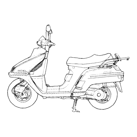
PARTS LOCATION nt temperature gauge Right rearview mirror (5) Left rearview mirror (4) Headlight dim ) Engine stop switch (13) Starter button (3) Turn signal swi (15) Ignition switch (1) Rear brake lock l e vel e ver... - Page 12 (2) Rear brake pedal (1) Passenger footrest...
- Page 13 (3) Passenger footrest...
- Page 14 PARTS FUNCTION Instrument and Indicators The indicators are grouped between the handlebars. Their functions are described in the table on the following page. USA model: Odometer reads in miles. Canadian model: Odometer reads in kilometers. (1) Left turn signal indicator (2) Fuel gauge (3) Digital clock (4) Speedometer...
- Page 15 Ref. No. Description Function Left turn signal indicator Flashes when the left turn signal operates. Shows approximate fuel supply available Fuel gauge (see page 12). Digital clock Shows the time (see page 14). Speedometer Shows riding speed (see page 12). Coolant temperature gauge Shows coolant temperature (see page 13).
- Page 16 Description Speedometer (km/h MPH) select button MPH (see page 12). ~~ _ _ _~~ Odometer Shows accumulated mileage. Shows approaching specified maintenance Maintenance indicator...
- Page 17 Fuel Gauge Speedometer The fuel gauge shows the approximate The speedometer display (1) shows riding fuel supply available. At F (Full) there speed. are 8.0 liters (2.1 US gal., 1.7 Imp. gal.), When the ignition switch is turned ON including the reserve supply. the display changes from 100 to 199 in When the gauge needle enters the red increments of 11(111,122,133,144...
- Page 18 Maintenance Indicator When the mileage on your scooter ap- Coolant Temperature Gauge proaches the specified maintenance inter- When the needle (1) begins to move val to change oil change, the maintenance above the C (Cold) mark (2), the engine indicator (1) will change from green to is warm enough to operate.
- Page 19 Digital Clock Battery Replacement The digital clock displays the time of day The digital clock’s battery compartment or night, and it has its own power source. is located under the tripmeter reset but- To adjust time, proceed as follows: ton. Remove the cover and install a new Turn the ignition switch to the ON posi- battery in the compartment.
- Page 20 MAJOR COMPONENTS (Information you need to operate this scooter) BRAKES Make sure the cut-out on the adjusting nut is seated on the brake arm pin (4) Adjustment: after making the final free play adjust- . Measure the distance the front brake ment.
- Page 21 COOLANT Coolant Recommendation The owner must properly maintain the cooling system performance and is recom- coolant to prevent freezing, overheating, mended only when additional protection and corrosion. Use only high quality against freezing is needed. A concentra- ethylene glycol antifreeze containing cor- tion of less than 40/60 (40% antifreeze) rosion protection inhibitors specifically will not provide proper corrosion protec-...
- Page 22 Inspection Remove the screw (1) attaching the front cover. Raise the front cover. Check the coolant level in the reserve tank (3) while the engine is at the normal operating temperature. If the coolant level is low, remove the reserve tank cap (2) and add coolant mixture until it reaches the UPPER level mark.
- Page 23 FUEL * Gasoline is extremely flammable and is Fuel Tank explosive under certain conditions. The fuel tank is located under the seat. Refuel in a well-ventilated area with Fuel tank capacity is 8.0 !? (2.1 US gal, the engine stopped. Do not smoke or 1.7 Imp gal).
- Page 24 Gasolines Containing Alkohol * Before purchasing fuel from an un- familiar station, try to confirm wheth- If you decide to use a gasoline containing er the fuel contains alcohol, and to alcohol (“gasohol”), be sure its octane what percentage. If you notice any un- rating is at least as high as tht recom- desirable operating symptoms after mended.
-
Page 25: Engine Oil Level Check
CAUTION : ENGINE OIL LEVEL CHECK Running the engine with insufficient Check the engine oil level each day be- oil can cause serious engine damage. fore riding the scooter. The level must be maintained between the upper (2) and lower (3) level marks on the dipstick (1). -
Page 26: Tubeless Tires
TUBELESS TIRES Check the tires for cuts, imbedded nails or other sharp objects. Check the rims for This scooter is equipped with tubeless dents or deformation. If there is any dam- tires, valves, and wheel rims. Use only age, see your authorized Honda scooter tires marked “TUBELESS”... - Page 27 CAUTION : Tire Repair/Replacement: Do not try to remove tubeless tires your authorized Honda Scooter Deal- without special tools and rim protec- tors. You may damage the rim sealing surface or disfigure the rim. * The use of tires other than those listed on the tire information label may ad- versely affect handling.
-
Page 28: Battery
BATTERY It is not necessary to check battery elec- trolyte level or add distilled water as the battery is a sealed type. If any loss of electrolyte is experienced or if your bat- tery seems to be weak, causing slow start- ing or other electrical troubles, see your authorized Honda dealer. - Page 29 (1) Ignition switch Key Removal Function Key Position LOCK The steering is locked. The engine and lights cannot be operated. Key can be removed. (Steering lock) O F F Engine and lights cannot be operated. Key can be removed. Taillight, headlight and position lamp will be on and other lights can be operated.
- Page 30 RIGHT HANDLEBAR CONTROLS Starter Button Engine Stop Switch The starter button (2) is below the engine stop switch (1). The engine stop switch (1) is next to the When the starter button is pressed, the throttle grip. When the switch is in the starter motor cranks the engine.
- Page 31 LEFT HANDLEBAR CONTROLS The three controls next to the left han- dle bar grip are: Headlight Dimmer Switch (1) Select HI for high beam, LO for low beam. Turn Signal Switch (2) Move to L to signal a left turn, R to signal a right turn.
- Page 32 REAR BRAKE LOCK Be sure to keep the rear brake lock is applied while starting and warming up the engine. To apply the brake lock: 1. Depress the rear brake pedal. 2. While holding the rear brake pedal down, pull up on the rear brake lock lever (1).
- Page 33 IGNITION SWITCH LIGHT An ignition switch light is provided to make it easier to find the switch when it is dark. To use this light, when the ignition switch is OFF, simply push the horn button. NOTE: * When the ignition switch is ON, push- ing the horn button will sound the horn.
- Page 34 FEATURES (Not required for operation) STEERING LOCK SEAT LOCK To lock the steering, turn the handlebars The seat lock (1) is below the left side of all the way to the left, and turn the key the seat. To lift the seat, insert the igni- (1) to LOCK while pushing in.
- Page 35 HELMET HOLDER To remove a helmet, unlock the seat. Lift the helmet off the holder and lower the The helmet holder (3) eliminates the need seat, making sure it is securely locked for carrying your helmet after parking before riding. your scooter.
- Page 36 GLOVE Opening To open the glove box, insert the igni- tion key (2) and turn it clockwise. Closing To close the glove box, insert the ignition key, turn it clockwise and close the glove box cover. Turn the key back to lock the glove box.
- Page 37 OPERATION Tires-check condition and pressure PRE-RIDE INSPECTION (page 2 1). Throttle-check for smooth opening If the Pre-ride Inspection is not per- and closing in all steering positions. formed, serious damage or an accident Lights and horn-check that the head- may result. light, tail/stoplight, turn signals, indi- cators and horn function properly.
- Page 38 STARTING THE ENGINE NOTE: The electric starter will only work NOTE: when the brake pedal (1) is operated. * This scooter has an automatic fuel valve and choke; there is no manual operation. The rear wheel will spin if not restrain- 1.
- Page 39 3. Make sure that the engine stop switch 5. With the throttle closed, push the is at RUN. starter button (4). Release the starter 4. Turn the ignition switch (3) to ON. button as soon as the engine starts. NOTE: Do not use the electric starter for * Never run the engine in a closed area.
- Page 40 NOTE: Be sure to keep the throttle (5) closed * If, after several attempts, you cannot and the rear brake pedal locked while restart a warm engine, hold the throttle starting and warming up the engine. l/8-1/4 open while starting the engine. Allow the engine to warm up before riding (See page 38 “RIDING”).
- Page 41 rear wheel will spin if not restrain. ed by the brake or contact with the ground. Accidental contact with the spinning rear wheel could cause personal injury. Do not leave the scooter u n a t t e n d e d while the engine is running.
- Page 42 BREAK-IN During the first 600 miles (1,000 km), do not operate the scooter at more than 80% of the maximum speed. Avoid full throttle operation, and do not operate for a long time at one speed. During initial break-in, newly machined surfaces will be in contact with each other and these surfaces will wear in quickly.
- Page 43 1. Make sure the throttle is closed and RIDING the rear brake is locked before moving EBzQEl the scooter off the center stand. The exhaust pipe and muffler become very hot during operation and remain * The rear wheel must be locked when sufficiently hot to inflict burns if moving the scooter off the center touched, even after shutting off the...
- Page 44 Once off the center stand, unlock the rear wheel releasing the rear brake lock (page 27). NOTE: Before riding, make sure that the rear brake is released completely and does not drag. WD!!DI Do not blip the throttle (open and close it rapidly as the scooter wiII move forward suddenly, causing pos- sible loss of control.
- Page 45 High Altitude Riding When operating this scooter at high alti- tude, the air-fuel mixture becomes over- ly rich. Above 6,500 feet (2,000 m), driveability and performance may be reduced and fuel consumption increased. The carburetor can be modified to com- pensate for this high altitude richness.
- Page 46 BRAKING clEm?El * When riding in wet or rainy conditions When slowing down the scooter, coordi- or on loose surfaces, the ability to nation of the throttle and front and rear maneuver and stop will be reduced. brakes are most important. For your safety, exercise extreme cau- tion when braking, accelerating, or * Both front and rear brakes should be...
- Page 47 ANTI-THEFT TIPS PARKING Always lock the steering and never 1. After stopping the scooter, turn the leave the key in the ignition switch. ignition switch OFF and remove the This sounds simple but people do key. 2. Use the center stand to support the forget.
- Page 48 MAINTENANCE The U.S. Environmental Protection Agency and California Air Resources Board (CARB) require that your scooter comply with applicable exhaust emissions standards during its useful life, when operated and maintained according to the instructions pro- vided, and that scooters built after January 1, 1983 comply with applicable noise emis- sion standards for one year or 6,000 km (3,730 miles) after the time of sale to the ulti- mate purchaser, when operated and maintained according to the instructions provided.
-
Page 49: Maintenance Schedule
MAINTENANCE SCHEDULE Perform the Pre-ride Inspection (Page 32) at each scheduled maintenance period. I: Inspect and clean, adjust, lubricate or replace if necessary C: Clean. R: Replace. A: Adjust. L: Lubricate. WHICHEVER+ ODOMETER READING (NOTE 3) COMES FIRST EVERY R P a g e 5 1 Replace Every 1,250 mi (2,COr CARBURETOR IDLE SPEED RADIATOR COOLANT... - Page 50 FREQUENCY WHICHEVER+ COMES FIRST EVERY * TRANSMISSION OIL DRIVE BELT (IIRII/IIRI BELT CASE AIR CLEANER NOTE( /C/Cjc/cI c I c I Page52 k_ BRAKE SHOE WEAR I / Page 59 IIIlIjI IELL BRAKE SYSTEM I I I BRAKE LOCK LEVER I/I/ BRAKE LIGHT SWITCH STARTER...
- Page 51 MAINTENANCE RECORD Make sure that whoever performs the maintenance completes this record. All scheduled maintenance including the 600 mile (1,000 km) break-in maintenance, is considered a normal owner operating cost and will be charged for by your authorized HONDA SCOOTER DEALER. Detailed receipts verifying the performance of required maintenance should be retain- ed.
- Page 52 TOOLKIT The tool kit is in the storage compart- ment in the glove box. Some roadside repairs, minor adjustments and part re- placement can be performed with the tools contained in the kit. 10x 12 Spanner No. 1 Screwdriver No. 2 Screwdriver No.
- Page 53 SERIAL NUMBERS The VIN, Vehicle Identification Number (l), is on the Safety Certification label, The frame and engine serial numbers are which is attached to left front cover. required when registering your scooter. The frame serial number (2) is stamped They may also be required by your on the rear of fuel tank under the seat.
- Page 54 COLOR LABEL The engine serial number (3) is stamped The color label is attached to the fuel on the back of the crankcase near the rear tank below the seat. It is helpful when wheel. ordering replacement parts. Record the color and code here for your reference.
-
Page 55: Components
MAINTENANCEPRECAUTIONS The Vehicle Emission Control Informa- tion Label (1) is attached below the seat. (USA ONLY) If your scooter is overturned or involv- The Vacuum Hose Routing Diagram ed in a collision, inspect control levers Label (2) is located below the seat. and cables, switches and other vital (CALIFORNIA ONLY) parts for damage. - Page 56 AIR CLEANER 3. Remove the air cleaner cover (2) by removing the screws. The air cleaner should be serviced at regu- 4. Remove the air cleaner element (3) by lar intervals (page 44). removing the screw and replace it with 1.
- Page 57 CAUTION: BELT CASE AIR CLEANER the element to dry thoroughly cover from * Allow 1. Remove the left side rear before installation. the frame. * Do not apply oil to the element, dam- duct band 2. Loosen the air cleaner age to the drive belt will occur.
- Page 58 CRANKCASEBREATHER Remove the drain plug ( 1) from the drain tube to empty any deposits. 2. Install the drain plug. NOTE: Service more frequently when riding in rain or at full throttle. plug (1) Drain...
- Page 59 Recoinmended Oil Viscosity ENGINE OIL SAE l0w-40 Engine Oil Recommendation Other viscosities shown in the chart 7 USE HONDA 4-STROKE OIL OR AN below may be used when the average EQUIVALENT. temperature in your riding area is within Use only high detergent, premium quality the indicated range.
- Page 60 Engine Oil and Filter Screen 1. Remove the oil filler cap from the right crankcase cover. Engine oil quality is a chief factor affec- 2. Place an oil drain pan under the crank- ting engine service life. Change the engine case and remove the oil drain plug (1).
- Page 61 Clean the oil filter screen (2). Stop the engine and check that the oil Check that the oil filter screen, sealing level is at the upper mark on the dip- rubber and drain plug O-ring are in stick with the scooter on its center good condition.
- Page 62 (2) carefully. SPARK PLUG 5. With the plug washer attached, thread Recommended plugs: the new spark plug in by hand to pre- Standard: vent cross-threading. DPR6EA-9 (NGK) or 6. Tighten the spark plug l/2 turn with a X20EPR-U9 (ND) spark plug wrench to compress the For cold climate (Below 5”C, 41°F): washer.
- Page 63 IDLE SPEED Warm up the engine and place the scooter on its center stand. The engine must be warm for accurate idle adjustment. Ten minutes of stop-and- go riding is sufficient. The rear wheel will spin if not restrain- NOTE: ed by the brake.
- Page 64 Other Checks: SHOE WEAR BRAKE Check the brake cable for kinks or signs Wear Indicator:. of wear that could cause sticking or fail- When the brake is applied, an arrow (2) ure . attached to the brake arm (3) moves to- Lubricate the brake cable with a commer- : ward a reference mark (1) on the brake cially available cable lubricant to prevent...
- Page 65 GOOD REPLACE SIDE STAND Check the rubber pad for deterioration and wear. Replace if wear extends to the wear line (1) as shown. Check the side stand spring for damage and loss of ten- sion, and the side stand assembly for freedom of movement.
-
Page 66: Ignition Switch
FUSE REPLACEMENT cm3ml The main fuse (1) is near the battery. The * Never use a fuse with a different rating specified fuse is 20A. from that specified. Serious damaae to The fuse box (2) is inside the glove box the electrical system or a fire may re- The specified fuses are 10A and a 5A’... - Page 67 Draining Fuel TRANSPORTING THE SCOOTER Perform this operation only in a well- ventilated area. Gasoline is flammable and explosive under certain conditions. Always stop the engine, and do not smoke or allow frames or sparks in the area when draining or refueling. Stop the engine and remove the center cover.
- Page 68 CLEANING 1. After cleaning, rinse the scooter thoroughly with plenty of clean water. Clean your scooter regularly to protect Strong detergent residue can corrode the surface finishes and inspect it for alloy parts. damage, wear, and oil seepage. 2. Dry the scooter, start the engine, and let it run for several minutes.
-
Page 69: Storage Guide
STORAGE GUIDE Gasoline is flammable and is explosive Storage under certain conditions. Do not Extended storage, such as for winter, re- smoke or allow flames or sparks near quires that you take certain steps to re- the equipment while draining fuel. duce the effects of deterioration from non-use of the scooter. - Page 70 Removal from Storage 5. Remove the battery. Store in an area protected from freezing temperatures 1. Uncover and clean the scooter. and direct sunlight. Change the engine oil if more than 4 6. Wash and dry the scooter. Wax all months have passed since the start of painted surfaces.
-
Page 71: Specifications
SPECIFICATIONS DIMENSIONS Overall length 1,920 mm (75.6 in) Overall width 715 mm (28.1 in) Overall height 1,115 mm (43.9 in) Wheel base 1,255 mm (49.4 in) Ground clearance 125 mm (4.9 in) WEIGHT Dry weight 122 kg (269 lbs) CAPACITIES Engine oil 1 .O Q (1.1 US qt.) After disassembly Fuel tank... - Page 72 ENGINE Bore and stroke 60 mm (2.83 x 2.36 in) Compression ratio 9.8 : 1 Displacement 244 cc (14.9 cu.in) Spark plug Standard X20EPR-U9 (ND) DPR6EA-9 (NGK) For cold climate Xl 6EPR-U9 (ND) (Below 5’C, 41’F) DPRSEA-9 (NGK) For extended high speed riding X22EPR-U9 (ND) DPR7EA-9 (NGK) Spark plug gap...
- Page 73 CHASSIS AND SUSPENSION 27”OO’ Caster Trail 79 mm (3.1 in) Tire size, front 4.00-10-4PR Tire size, rear 4.00-l0-4PR ELECTRICAL 12V-12Ah Battery Alternator A.C. Generator : POWER TRANSMISSION 1.00 Primary reduction Final reduction 1.00 _B L I G H T S Headlight 12v-60/55W 12V-8/27W...
- Page 74 /CONSUMER INFORMATION 1 (USA ONLY) VEHICLE STOPPING DISTANCE This figure indicates braking performance that can be met or exceeded by the vehicles to which it applies, under different conditions of loading. The information presented represents results obtainable by skilled drivers under controlled road and vehicle conditions.
- Page 75 Carbon monoxide does not react in the same way, but it is toxic. Honda Motor Co., Ltd. utilizes lean carburetor settings to reduce carbon monoxide and hydrocar- bons.
- Page 76 Evaporative Emission Control Svstem (California only) This motorcycle complies with the California Air Resources Board (CARB) require- ments for evaporative emission regulations. Fuel vapor from the fuel tank is directed into the charcoal canister where it is absorbed and stored while the engine is stopped. When the engine is running, fuel vapor in the charcoal canister is drawn into the engine through the carburetor.
- Page 77 Your purchase of a Honda product is greatly appreciated by both the dealer and Ameri- can Honda Motor Co., Inc. We want to assist you in every way possible to assure your complete satisfaction with your purchase.
- Page 78 OFFICE customer Ral.tmn* D*pMm*“l lmclud ing Puerto Rico) SOVTHWEST REGIONAL OFFICE P O BO”120 American Honda Motor co 1°C &ne,,c,n Hod. Motor Co 1°C G.rd.n.. C.h‘ornm 90247 Customer Ralatians Departmsnt C”l,ome, Rdmon* Dap.Rmsnt T.l.phon. ,213,60*2624 1500 MOrnsOn Parkway P 0 BOX 6.06 Alpharetta.