Table of Contents
Advertisement
Quick Links
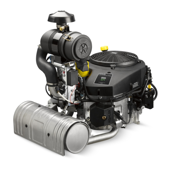
ECV940 & ECV980
Service Manual
IMPORTANT:
Read all safety precautions and instructions carefully before operating equipment. Refer to operating
instruction of equipment that this engine powers.
Ensure engine is stopped and level before performing any maintenance or service.
2
Safety
3
Maintenance
5
Specifi cations
13
16
20
21
Electronic Fuel Injection (EFI) System
45
55
57
62
66
83
62 690 05 Rev. --
KohlerEngines.com
1
Advertisement
Table of Contents
Troubleshooting

Related Manuals for Kohler ECV940


Summary of Contents for Kohler ECV940
- Page 1 ECV940 & ECV980 Service Manual IMPORTANT: Read all safety precautions and instructions carefully before operating equipment. Refer to operating instruction of equipment that this engine powers. Ensure engine is stopped and level before performing any maintenance or service. Safety Maintenance Specifi...
- Page 2 Safety SAFETY PRECAUTIONS WARNING: A hazard that could result in death, serious injury, or substantial property damage. CAUTION: A hazard that could result in minor personal injury or property damage. NOTE: is used to notify people of important installation, operation, or maintenance information. CAUTION WARNING WARNING...
- Page 3 Perform these procedures more frequently under severe, dusty, dirty conditions. REPAIRS/SERVICE PARTS Kohler genuine service parts can be purchased from Kohler authorized dealers. To fi nd a local Kohler authorized dealer visit KohlerEngines.com or call 1-800-544-2444 (U.S. and Canada). 62 690 05 Rev. --...
- Page 4 OIL RECOMMENDATIONS STORAGE If engine will be out of service for 2 months or more We recommend use of Kohler oils for best performance. follow procedure below. Other high-quality detergent oils (including synthetic) of API (American Petroleum Institute) service class SJ 1.
-
Page 5: Engine Dimensions
Specifi cations Engine Dimensions Dimensions in millimeters. Inch equivalents shown in [ ]. 484.61 [19.08] 152.50 [6.00] 50.00 [1.97] 325.25 680.87 [12.81] [26.81] 20.01 22.50 45.00 [1.77] [0.79] [0.89] 403.69 406.25 30.00 [15.89] [15.99] [1.18] 168.71 [6.64] 62.70 [2.47] SPARK PLUG MOUNTING HOLE “A”... - Page 6 Kohler engine identifi cation numbers (model, specifi cation and serial) should be referenced for effi cient repair, ordering correct parts, and engine replacement. Model ..... ECV940 EFI Command Engine...
- Page 7 Specifi cations TORQUE SPECIFICATIONS ECV940 ECV980 Crankcase Breather Cover Fastener 12.4 N·m (110 in. lb.) Oil Drain Plug 21.4 N·m (16 ft. lb.) Oil Temperature Sensor 7.3 N·m (65 in. lb.) Dipstick Tube Screw 7.7 N·m (68 in. lb.) Cylinder Head...
- Page 8 Specifi cations TORQUE SPECIFICATIONS ECV940 ECV980 Muffl er Retaining Nut 24.4 N·m (216 in. lb.) Screw, intermittent bracket (into weld nut) 13.6 N·m (120 in. lb.) M6 Screw 9.9 N·m (88 in. lb.) M8 Screw 24.4 N·m (216 in. lb.)
- Page 9 Specifi cations CLEARANCE SPECIFICATIONS ECV940 ECV980 Camshaft End Play 0.3/1.3 mm (0.011/0.051 in.) Running Clearance 0.025/0.063 mm (0.0010/0.0025 in.) Bore I.D. 20.000/20.025 mm (0.7874/0.7884 in.) Max. Wear Limit 20.038 mm (0.7889 in.) Bearing Surface O.D. 19.962/19.975 mm (0.7859/0.7864 in.) Max. Wear Limit 19.959 mm (0.7858 in.)
- Page 10 Specifi cations CLEARANCE SPECIFICATIONS ECV940 ECV980 Crankshaft Continued T.I.R. PTO End, Crank in Engine 0.279 mm (0.0110 in.) Entire Crank, in V-Blocks 0.10 mm (0.0039 in.) Flywheel End Main Bearing Journal O.D. - New 44.978/45.00 mm (1.770/1.771 in.) O.D. - Max. Wear Limit 44.90 mm (1.767 in.)
- Page 11 Specifi cations CLEARANCE SPECIFICATIONS ECV940 ECV980 Piston, Piston Rings, and Piston Pin Continued Thrust Face O.D. 89.953/89.967 mm (3.5414/3.5420 in.) Max. Wear Limit 89.925 mm (3.540 in.) Piston Thrust Face-to-Cylinder Bore Running Clearance 0.033/0.071 mm (0.0013/0.0028 in.) Valves and Valve Lifters Hydraulic Valve Lifter to Crankcase Running Clearance 0.012/0.050 mm (0.0004/0.0019 in.)
- Page 12 Specifi cations GENERAL TORQUE VALUES English Fastener Torque Recommendations for Standard Applications Bolts, Screws, Nuts and Fasteners Assembled Into Cast Iron or Steel Grade 2 or 5 Fasteners Into Aluminum Size Grade 2 Grade 5 Grade 8 Tightening Torque: N·m (in. lb.) ± 20% 8-32 2.3 (20) 2.8 (25)
- Page 13 Here is a list of tools and their source. SEPARATE TOOL SUPPLIERS Kohler Tools SE Tools Design Technology Inc. Contact your local Kohler source of 415 Howard St. 768 Burr Oak Drive supply. Lapeer, MI 48446 Westmont, IL 60559...
- Page 14 For reaming worn valve guides to accept replacement oversize valves. Can be used in low-speed drill press or with handle below for hand reaming. Reamer Handle Design Technology Inc. For hand reaming using Kohler 25 455 12-S reamer. DTI-K830 Valve Guide Service Kit (Courage, Aegis, Command, OHC) SE Tools KLR-82415 For servicing worn valve guides.
- Page 15 Tools and Aids FLYWHEEL HOLDING TOOL ROCKER ARM/CRANKSHAFT TOOL A fl ywheel holding tool can be made out of an old junk A spanner wrench to lift rocker arms or turn crankshaft fl ywheel ring gear and used in place of a strap wrench. may be made out of an old junk connecting rod.
-
Page 16: Troubleshooting
Troubleshooting TROUBLESHOOTING GUIDE When troubles occur, be sure to check simple causes which, at fi rst, may seem too obvious to be considered. For example, a starting problem could be caused by an empty fuel tank. Some general common causes of engine troubles are listed below and vary by engine specifi cation. Use these to locate causing factors. - Page 17 Troubleshooting EXTERNAL ENGINE INSPECTION Engine Loses Power NOTE: It is good practice to drain oil at a location away ● Dirty air cleaner element. from workbench. Be sure to allow ample time for ● Engine overheated. complete drainage. ● Excessive engine load. ●...
- Page 18 Troubleshooting CRANKCASE VACUUM TEST WARNING WARNING Carbon Monoxide can cause severe nausea, Rotating Parts can cause severe injury. fainting or death. Stay away while engine is in operation. Avoid inhaling exhaust fumes. Engine exhaust gases contain poisonous carbon Keep hands, feet, hair, and clothing away from all monoxide.
- Page 19 Troubleshooting COMPRESSION TEST For Command Twins: A compression test is best performed on a warm engine. Clean any dirt or debris away from base of spark plug(s) before removing them. Be sure choke is off, and throttle is wide open during test. Compression should be at least 160 psi and should not vary more than 15% between cylinders.
-
Page 20: Air Cleaner/Intake
Air Cleaner/Intake AIR CLEANER BREATHER TUBE These systems are CARB/EPA certifi ed and components Ensure both ends of breather tube are properly should not be altered or modifi ed in any way. connected. AIR COOLING WARNING Hot Parts can cause severe burns. Do not touch engine while operating or just after stopping. - Page 21 FUEL LINE compensation for changes in overall engine condition Low permeation fuel line must be installed on all Kohler and operating environment, so it will be able to maintain Co. engines to maintain EPA and CARB regulatory compliance.
- Page 22 EFI SYSTEM ECU compares input signals to programmed maps in Crankshaft position sensor is essential to engine its memory to determine appropriate fuel and spark operation; constantly monitoring rotation and speed requirements for immediate operating conditions. ECU (RPM) of crankshaft. There are 23 consecutive teeth then sends output signals to set injector duration and cast into fl...
- Page 23 EFI SYSTEM Tip of sensor, protruding into exhaust gas, is hollow. EFI engines are equipped with either a 20 or 25 amp Outer portion of tip is surrounded by exhaust gas, with charging system to accommodate combined electrical inner portion exposed to ambient air. When oxygen demands of ignition system and specifi...
- Page 24 EFI SYSTEM High pressure fuel line is serviced as a complete IMPORTANT NOTES! assembly to prevent tampering and safety hazards. ● Cleanliness is essential and must be maintained at all Components are not individually serviceable. times when servicing or working on EFI system. Dirt, Vent hose assembly is intended to vent fuel vapor out of even in small quantities, can cause signifi...
- Page 25 EFI SYSTEM ELECTRICAL COMPONENTS Grey Connector Electronic Control Unit (ECU) Pin # Description Pinout of ECU Not Used Black Connector Not Used Pin # Function Malfunction Indicator Light (MIL) Ground Ignition Coil #1 Ground Not Used Battery Ground Not Used Diagnostic Communication Line GCU Tach Output Speed Sensor input...
- Page 26 ECU Reset Procedure 1. Turn key/ignition OFF. 2. Install Red wire jumper from Kohler EFI service kit on to service port (connect white wire to black wire in 4 way diagnostic port). 3. Turn key/ignition ON, then OFF and count 10 seconds.
- Page 27 EFI SYSTEM 62 690 05 Rev. -- KohlerEngines.com...
- Page 28 EFI SYSTEM Crankshaft Position Sensor b. Hold throttle closed and check resistance. It A sealed, non-serviceable assembly. If Fault Code should be 1400-1800 Ω. diagnosis indicates a problem within this area, test and 4. Leave leads connected to pin terminals as described correct as follows.
- Page 29 EFI SYSTEM 6. Check circuits (input, ground), from wire harness connector to sensor plug for continuity, damage, etc. Connect one ohmmeter lead to Black pin 14 in wire harness connector (as in step 4). Connect other lead to terminal #1 in sensor plug. Continuity should be indicated.
- Page 30 EFI SYSTEM Sensor Signal Observation Removal Inspection NOTE: Do not cut into or pierce sensor or engine NOTE: Apply anti-seize compound only to threads. wiring to make this connection. Sensor Anti-seize compound will affect sensor produces a very small signal. Corrosion or performance if it gets into lower shield of damage to wiring could lead to an incorrect sensor.
- Page 31 EFI SYSTEM Troublshooting-Oxygen Sensor (O Condition Possible Cause Conclusion Low voltage output. Shorted sensor or sensor circuit. Replace sensor or repair wiring. Shorted lead wire. Wiring shorted to ground. Contamination of air reference. Remove source of external contamination, protect air reference area.
- Page 32 EFI SYSTEM 2. Disconnect electrical connector from an injector and Fuel Injectors listen for a change in idle performance (only running on one cylinder) or a change in injector noise or vibration. WARNING Explosive Fuel can cause fi res and severe If an injector is not operating, it can indicate either a bad burns.
- Page 33 NOTE: If ignition coil(s) are disabled and an ignition pump module and insert pressure test jumper (from fault is registered, system will automatically Kohler EFI Service Kit) between high pressure fuel disable corresponding fuel injector drive line and fuel pump module.
- Page 34 Please note vent hose routing and replicate after service or component replacement to prevent pinching or abrasion of vent hoses. Only Kohler replacement parts can be used because fi tting is specifi c to system and must be maintained. Visit KohlerEngines.com for recommended Kohler replacement parts.
- Page 35 EFI SYSTEM Troubleshooting Guide Condition Possible Cause Faulty spark plugs. Fuel pump not running. Fuel pressure low. Insuffi cient fuel delivery. Engine Starts Hard or Fails to Start TPS set incorrect (ECU Reset and TPS Initialization). When Hot. Crankshaft position sensor loose or faulty. TPS faulty.
- Page 36 EFI SYSTEM Function Test Fault Codes Example of Diagnostic Display WARNING High Pressure Fluids can puncture skin and cause severe injury or death. One second pause Do not work on fuel system without proper Fault training or safety equipment. Code One second pause Fluid puncture injuries are highly toxic and hazardous.
- Page 37 EFI SYSTEM 0230 Fuel Pump Module Circuit Low Voltage or Open 0232 Fuel Pump Module Circuit High Voltage 0336 Crankshaft Position Sensor Noisy Signal 0337 Crankshaft Position Sensor No Signal 0351 Cylinder 1 Ignition Coil Malfunction 0352 Cylinder 2 Ignition Coil Malfunction 0562 System Voltage Low 0563...
- Page 38 EFI SYSTEM Code 0107 Code 0113 Component: Manifold Absolute Pressure Sensor Component: Intake Air Temperature Sensor Fault: MAP Circuit Low Voltage or Open Fault: Intake Air Temperature Sensor Circuit High Voltage or Open Condition: Intake manifold leak, open connection or faulty sensor.
- Page 39 EFI SYSTEM Code 0122 Code 0131 Component: Throttle Position Sensor (TPS) Component: Oxygen Sensor Fault: TPS Circuit Low Voltage or Open Fault: O2S 1 Circuit Low Voltage Condition: Open connection, broken wire or faulty Condition: Open connection, broken wire or faulty sensor.
- Page 40 EFI SYSTEM Code 0171 Code 0172 Component: Fuel System Component: Fuel System Fault: Maximum adaptation limit exceeded Fault: Minimum adaptation limit exceeded Condition: Fuel inlet screen/fi lter plugged, low Condition: Too high pressure at high pressure fuel pressure at high pressure fuel line, TPS line, TPS malfunction, shorted malfunction, shorted connection, faulty connection, faulty sensor or fuel pump...
- Page 41 EFI SYSTEM Code 0174 Code 0202 Component: Fuel System Component: Fuel Injector Fault: Lean fuel condition Fault: Injector 2 Circuit Malfunction Condition: Fuel inlet screen/fi lter plugged, low Condition: Injector damaged or faulty, shorted or pressure at high pressure fuel line, TPS open connection.
- Page 42 EFI SYSTEM Code 0336 Code 0352 Component: Crankshaft Position Sensor Component: Ignition Coil Fault: Crankshaft Position Sensor Noisy Signal Fault: Cylinder 2 Ignition Coil Malfunction Condition: Air gap incorrect, loose sensor, faulty/bad Condition: Broken wire in harness (may not be battery, shorted or faulty connection, visible), shorted connection or faulty faulty sensor or faulty sensor grounding.
- Page 43 NOTE: MIL is installed by vehicle OEM. Twelve volt (no fuel delivery) supply to bulb will be part of vehicle wire harness. Kohler key switch model will have MIL Condition on engine with 12V supply to bulb. ● No fuel ●...
- Page 44 EFI SYSTEM EFI Diagnostic Flow Diagram START OF TEST PROCEED TO START OF TEST FOR RETEST KEY ON MALFUNCTION REFER TO DIAGNOSTIC AID #1 INDICATOR LIGHT SYSTEM POWER REFER TO ARE FAULT CODES DIAGNOSTIC FAULT CODE SUMMARY PRESENT? CLEAR CODES REFER TO DIAGNOSTIC AID #3 DOES ENGINE START? MIL GOES OFF?
-
Page 45: Governor System
Governor System GOVERNOR These engines are equipped with an electronic governor or a mechanical governor. ELECTRONIC GOVERNOR Components Governor Control Digital Linear DLA Throttle Plate Wiring Harness Unit (GCU) Actuator (DLA) Mounting Screws Throttle Body Throttle Body Lever Connector Linkage Spring Assembly Adapter Plastic Linkage... - Page 46 Governor System 4. Place clevis shaft into actuator. Rotate clevis shaft Linkage clockwise 3 full turns, applying slight pressure, until NOTE: Throttle linkage spring must be in place and you feel clevis shaft keyway make contact with key installed correctly to ensure proper throttle in actuator.
- Page 47 Governor System Test 2 Probe Location Test 2 Probe Location Probe Location for Voltage Test 2. Probe Locations for OHMs Test 2. Test 2: Identify probe location in connector. Using a Test 2: Identify probe locations in connector. Using a 12 volt meter test for voltage.
- Page 48 Governor System GCU Blink Code Tests Speed control issues can also be diagnosed utilizing on-board Blink Code diagnostic lights equipped in GCU. These GCUs store blink codes/trouble codes, that can be quickly diagnosed using blink code charts. Green LED Light Yellow LED Light GCU Blink Codes for Software Stored Codes - Activated when key is turned to ON position.
- Page 49 Governor System GCU Blink Codes for Software Running Codes - Activated when engine is running. Response LED Diagnostics Failure Condition Possible Causes Response Time Yellow LED Green LED Running Normally None BLINKS BLINKS RPM Too High Mechanical bindage None BLINKS RPM Too Low Mechanical bindage None...
- Page 50 Governor System Electronic Governor Troubleshooting Flow Chart Turn off key switch. Do Not Touch Digital Linear Actuator (DLA) NOTE: DLA is not a solenoid. It is a precision electronic motor. Do not exert force to center clevis shaft! Visually inspect DLA and Linkage. See illustrations on page 45. Confi...
- Page 51 Engine speed increases Operation Input Voltage: (if it was at low speed). 0-1 Volts at Idle/9+ Volts at High Speed. Kohler electronic governor system tests OK. Test Fail Pass control system of equipment. Refer to Equipment Manufacturer’s diagnostic procedures for control system.
- Page 52 Governor System Electronic Governor Troubleshooting Flow Chart Continued Turn key switch to ON position. Test supply voltage to GCU using volt meter. Refer to page 47 (battery voltage +/- 1 volt) Note: Prevent Damage to Connector. Do Not Use Oversized Probe Tips. Proceed to DLA Circuit Test.
- Page 53 Governor System MECHANICAL GOVERNOR Governed speed setting is determined by position of throttle control. It can be variable or constant, depending on engine application. Governor is designed to hold engine speed constant under changing load conditions. Governor gear/fl yweight mechanism is mounted inside crankcase and is driven off gear on camshaft. Components Inside Engine Throttle Lever...
- Page 54 Governor System Governor Adjustments NOTE: Do not tamper with governor setting. Overspeed is hazardous and could cause personal injury. Initial Adjustment Procedure Make this adjustment whenever governor arm is loosened or removed from cross shaft. Adjust as follows: 1. Make sure throttle linkage is connected to governor arm and throttle lever on throttle body. 2.
-
Page 55: Lubrication System
Lubrication System This engine uses a full pressure lubrication system which delivers oil under pressure to crankshaft, camshaft, connecting rod bearing surfaces, and hydraulic valve lifters. A high-effi ciency gerotor oil pump maintains high oil fl ow and oil pressure, even at low speeds and high operating temperatures. - Page 56 Lubrication System OIL COOLER Installation NOTE: Oil cooler is mounted under cylinder shroud. 1. Apply pipe sealant with Tefl on (Loctite 592™ ® ® ® Removal of cylinder shroud is necessary to Thread Sealant or equivalent) to threads of switch. access oil cooler.
-
Page 57: Electrical System
Electrical System SPARK PLUGS Inspection Inspect each spark plug as it is removed from cylinder CAUTION head. Deposits on tip are an indication of general Electrical Shock can cause injury. condition of piston rings, valves, and carburetor. Do not touch wires while engine is running. Normal and fouled plugs are shown in following photos: Normal Spark Plug Component and Details... - Page 58 Electrical System Carbon Fouled BATTERY A 12-volt battery with 400 cold cranking amps (cca) is generally recommended for starting in all conditions. A smaller capacity battery is often suffi cient if an application is started only in warmer temperatures. Refer to following table for minimum capacities based on anticipated ambient temperatures.
- Page 59 Electrical System BATTERY CHARGING SYSTEM NOTE: Observe following guidelines to avoid damage to electrical system and components: ● Make sure battery polarity is correct. A negative (-) ground system is used. ● Disconnect rectifi er-regulator plug and/or wiring harness plug before doing any electric welding on equipment powered by engine.
- Page 60 Electrical System Condition Conclusion 20/25 amp OK (green) light comes on and stays steady. Disconnect tester black lead attached to 1 AC terminal and reconnect it to other AC terminal. Repeat test. If OK (green) light comes on again, part is good and may be used.
- Page 61 Electrical System FUSES This engine has 3 blade type automotive fuses. Replacement fuses must have same rating as blown fuse. Use fuse chart below to determine correct fuse. Wire Color Fuse Rating 2 Purple Wires 30-amp Fuse 1 Red Wire w/ Black Stripe 10-amp Fuse 1 Red Wire w/ White Stripe 2 Red Wires...
-
Page 62: Starter System
Starter System NOTE: Do not crank engine continuously for more than 10 seconds. Allow a 60 second cool down period between starting attempts. Failure to follow these guidelines can burn out starter motor. NOTE: If starter is engaged while fl ywheel is rotating, starter pinion and fl ywheel ring gear may clash and damage starter. - Page 63 Starter System SOLENOID SHIFT STARTERS Starter Disassembly When power is applied to starter electric solenoid moves NOTE: Do not reuse old retainer. drive pinion out onto drive shaft and into mesh with NOTE: Do not soak armature or use solvent when fl...
- Page 64 4 brushes and springs are serviced as a set. Use a new holes in metal clips must be up/out. Slide brush Kohler brush and spring kit if replacement is necessary. holder assembly down into place around 1. Perform steps 1-5 in Starter Disassembly.
- Page 65 Starter System c. Install brush springs and snap on retainer caps. d. Hold starter assembly vertically on end housing, and carefully place tool (with extension) and assembled original brush holder assembly onto end of armature shaft. Slide brush holder assembly down into place around commutator, install positive (+) brush lead grommet in cutout of frame.
- Page 66 Disassembly/Inspection and Service WARNING Before working on engine or equipment, disable engine as Accidental Starts can cause severe injury or follows: 1) Disconnect spark plug lead(s). 2) Disconnect death. negative (–) battery cable from battery. Disconnect and ground spark plug lead(s) before servicing.
- Page 67 Disassembly/Inspection and Service Clean all parts thoroughly as engine is disassembled. Remove Fuel Pump Module/Fuel Pump Assembly Only clean parts can be accurately inspected and gauged for wear or damage. There are many WARNING commercially available cleaners that will quickly remove grease, oil and grime from engine parts.
- Page 68 Disassembly/Inspection and Service 3. Remove screws and #2 side valley baffl e. Remove #2 Barrel and Valley Baffl es 4. If necessary, carefully depress clip & remove coil 1. Disconnect wiring harness lead from coil (#2 oil from barrel baffl e. cooler side).
- Page 69 fl ywheel, crankshaft, and key if fl ywheel key is sheared or keyway is damaged. Inspect ring gear for cracks or damage. Kohler does not provide ring gear as a serviceable part. Replace fl ywheel if ring gear is damaged.
- Page 70 Disassembly/Inspection and Service NOTE: Further disassembly of oil fi lter housing Perform following only if oil fi lter housing assembly assembly is not required unless being serviced requires individual servicing. individually. Follow substeps a, b, and c. a. Remove nipple from cup and oil fi lter housing. 1.
- Page 71 If lifters need to be replaced, apply a liberal engine while intake lifters are located on fan side coating of Kohler lubricant to base of each new lifter of engine. Cylinder head number is embossed before it is installed.
- Page 72 Disassembly/Inspection and Service Inspection and Service Valve Details EXHAUST VALVE INTAKE VALVE Dimension Intake Exhaust Seat Angle 89° 89° Seat Taper 30° 30° Guide Depth 8.5 mm (0.334 in.) 8.5 mm (0.334 in.) Guide I.D. 7.038/7.058 mm (0.2771/0.2779 in.) 7.038/7.058 mm (0.2771/0.2779 in.) Valve Head Diameter 38.625/38.685 mm (1.5206/1.5230 in.) 31.625/31.825 mm (1.2450/1.2549 in.)
- Page 73 Disassembly/Inspection and Service Recondition valve seat inserts following instructions of grinding compound, then rotate valve on its seat with provided with valve seat cutter being used. Final cut grinder. Continue grinding until a smooth surface is should be made with an 89° cutter as specifi ed for obtained on seat and on valve face.
- Page 74 Disassembly/Inspection and Service Crankshaft Bearing Oil Pan Gasket Breather Filter Breather Gasket (PTO) Breather Assembly Oil Seal Reassembly Remove Breather Assembly Torque Sequence 1. Carefully remove harness clip from #1 valley baffl e (if not already removed). 2. Remove fasteners securing breather assembly and gasket to crankcase.
- Page 75 Disassembly/Inspection and Service Crankcase Components Remove Camshaft Remove camshaft and shim (if used). Inspection Check lobes of camshaft for wear or damage. Inspect cam gear for badly worn, chipped, or missing teeth. Replacement of camshaft will be necessary if any of these conditions exist.
- Page 76 Disassembly/Inspection and Service When cylinder temperatures get too high, lacquer and Piston and Rings varnish collect on pistons causing rings to stick, which Inspection results in rapid wear. A worn ring usually takes on a Piston and Rings Components and Details shiny or bright appearance.
- Page 77 Disassembly/Inspection and Service 2. Middle compression ring (center groove): Install Inspect gear teeth of crankshaft. If teeth are badly worn, center ring using a piston ring installation tool. Make chipped, or some are missing, replacement of crankshaft sure identifi cation mark is up or colored dye stripe (if will be necessary.
- Page 78 Remove Flywheel End Oil Seal Remove oil seal from crankcase using a seal puller. 23°-33° Crosshatch NOTE: Kohler pistons are custom-machined to exacting tolerances. When oversizing a cylinder, it should be machined exactly 0.25 mm (0.010 in.) or 0.50 mm (0.020 in.) over new diameter.
- Page 79 Disassembly/Inspection and Service 1. Lower hone into bore and after centering, adjust so Measuring Piston-to-Bore Clearance stones are in contact with cylinder wall. Use of a Piston Detail commercial cutting-cooling agent is recommended. 2. With lower edge of each stone positioned even with lowest edge of bore, start drill and honing process.
- Page 80 Disassembly/Inspection and Service Electronic Governor Intake and Throttle Body Assembly Components Elbow Elbow O-ring Throttle Body Intake Manifold Fuel Rail Assembly Breather Hose Injector MAP Sensor Air Cleaner Bracket Air Temperature Lifting Bracket Assembly Sensor Throttle Body Lever Linkage & Spring GCU Bracket DLA Bracket Adapter...
- Page 81 Disassembly/Inspection and Service Mechanical Governor Intake and Throttle Body Assembly Components Elbow Elbow O-ring Throttle Body Intake Manifold Fuel Rail Assembly Breather Hose Injector MAP Sensor Air Cleaner Bracket Air Temperature Speed Control Assembly Sensor Bracket Throttle Linkage Linkage Spring 7.
- Page 82 Disassembly/Inspection and Service Remove ECU Fuel Pump Module/Pump Assembly Components 1. Remove screws securing ECU to bracket. 2. Disconnect black and grey electrical connectors from ECU. 3. Reverse procedure to install. Torque screws to 6.2 N·m (55 in. lb.). Remove Fuel Injectors 1.
- Page 83 Reassembly NOTE: Make sure engine is assembled using all Crankcase Components specifi ed torque values, torque sequences, and clearances. Failure to observe specifi cations could cause severe engine wear or damage. Always use new gaskets. Apply a small amount of oil to threads of critical fasteners before assembly, unless a sealant or Loctite ®...
- Page 84 Reassembly Install Governor Shafts, Seal, and Governor Gear Install Crankshaft (Mechanical Governor only) Carefully slide fl ywheel end of crankshaft through oil seal Governor Components and Details in crankcase. Install Connecting Rods with Pistons and Rings Piston Details Side 1 Side 2 Top of Piston NOTE: Cylinders are numbered on crankcase.
- Page 85 Reassembly 3. No shim is typically used from factory. However, if Install Camshaft camshaft end play is not within specifi ed range, 1. Liberally apply camshaft lubricant to each cam lobe. remove checking tool and shim as necessary. Lubricate camshaft bearing surfaces of crankcase Several color coded shims are available: and camshaft with engine oil.
- Page 86 Reassembly Breather/Oil Pan Components Breather Fastener Torque Sequence Oil Pan Gerotor Gears Oil Pump O-Ring Oil Pump Housing Pickup Tube Inlet Seal Pickup Screen Drain Plug Crankshaft Bearing Oil Pan Gasket Breather Filter Breather Gasket (PTO) Breather Assembly Oil Seal 2.
- Page 87 Reassembly PTO Oil Seal 1. Make sure sealing surfaces of oil pan and crankcase Details are clean, dry, and free of any nicks or burrs. Install a new O-ring in oil pan. 2. Install a new oil pan gasket onto crankcase. 3.
- Page 88 Reassembly Cylinder Head Components Gasket Valve Cylinder Head Pipe Plug Guide Plate Spacer Washer Spark Plug Valve Stem Seal Valve Spring Valve Spring Retainer Hydraulic Lifter Valve Spring Keeper Push Rod Rocker Arm Rocker Arm Pivots Rocker Stud Valve Cover Seal Valve Cover Grommet Non-adjustable Valve...
- Page 89 Reassembly Adjustable Valve Train Install Cylinder Heads 1. Install push rod guide plate and rocker arm pivot Torque Sequence studs onto cylinder heads if removed previously. Torque studs to 11.3 N·m (100 in. lb.). 2. Note mark or tag identifying push rod as either intake or exhaust and cylinder 1 or 2.
- Page 90 Reassembly 4. Viewed from PTO end, rotate crankshaft 270° (3/4 Oil Cooler/Filter Components turn) counterclockwise and align crankshaft keyway with cylinder 2, which now puts that cylinder at TDC on compression stroke. 5. Repeat steps 3-5 for setting valve clearance on cylinder 2.
- Page 91 Reassembly Backing Shroud/Intake Manifold/Throttle Body/Air Cleaner/Flywheel/Fan Assembly Components Special Washer Debris Screen Stiffener Flywheel Screw Backing Shroud/ Flywheel/Fan/Hex Intake Manifold/ Washer Speed Sensor Stud Assembly Air Cleaner Assembly Rectifi er-Regulator MAP Sensor Stator Ground Lead Connector Connector Oil Temperature Breather Hose Oil Sentry Reducer Bushing Sensor...
- Page 92 Reassembly Install Intake Manifold/Throttle Body//Air Cleaner/ Install Ground Lead and Rectifi er-Regulator Backing Shroud Assembly Connector Intake Manifold Torque Sequence 1. Attach ground lead to outer rectifi er-regulator mounting screw and washer, then torque mounting screw to 2.5 N·m (22 in. lb.). 2.
- Page 93 Reassembly External Engine Components Dipstick Oil Drain Plug Oil Fill Tube Valley Baffl e Spark Plug Lead Barrel Baffl e Starter Assembly Ignition Coil Fuel Pump Module Fuel Filter Fuel Pump Module Fuel Pump Bracket High Pressure Fuel Electrical Connector Evap Line Oil Cooler Line Connector...
- Page 94 Reassembly Install Valley and Cylinder Barrel Baffl es Install Electric Starter 1. Install #1 side valley baffl e and secure with 3 1. Install electric starter motor using screws. screws. Reinstall clip securing harness to baffl e. 2. Torque screws to 16 N·m (142 in. lb.). Install #2 side valley baffl...
- Page 95 Reassembly Mechanical Governor Control Bracket Components Throttle Lever Control Bracket Throttle Linkage Linkage Spring Cross Shaft Governor Lever Governor Spring Idle Spring Install Governor Lever (Mechanical Governor Only) Install Oil Sentry (if equipped) ™ Install governor lever onto governor shaft and connect 1.
- Page 96 Reassembly Install Oil Filter and Add Oil to Crankcase Testing Engine NOTE: Make sure both oil drain plugs are installed and It is recommended engine be operated on a test stand or torqued to 21.4 N·m (16 ft. lb.). to prevent oil bench prior to installation in equipment.
- Page 97 62 690 05 Rev. -- KohlerEngines.com...
- Page 98 KohlerEngines.com 62 690 05 Rev. --...
- Page 99 62 690 05 Rev. -- KohlerEngines.com...
- Page 100 1P62 690 05 © 2013 by Kohler Co. All rights reserved. 85612 22194 KohlerEngines.com 62 690 05 Rev. --...