Yamaha TDM850 Owner's Manual
1999
Hide thumbs
Also See for TDM850:
- Owner's manual (110 pages) ,
- User manual (212 pages) ,
- Owner's manual (103 pages)
Table of Contents
Advertisement
Quick Links
Advertisement
Chapters
Table of Contents
Troubleshooting

Related Manuals for Yamaha TDM850


Summary of Contents for Yamaha TDM850
- Page 1 OWNER’S MANUAL TDM850 4TX-28199-E4...
- Page 2 EAU00001 Welcome to the Yamaha world of motorcycling! As the owner of a TDM850, you are benefiting from Yamaha’s vast experience in and newest technology for the design and the manufacture of high-quality products, which have earned Yamaha a reputation for dependability.
- Page 3 This manual should be considered a permanent part of this motorcycle and should remain with it even if the motorcycle is subsequently sold. Yamaha continually seeks advancements in product design and quality. Therefore, while this manual contains the most current product information available at the time of printing, there may be minor discrepancies between your motorcycle and this manual.
-
Page 4: Important Manual Information
IMPORTANT MANUAL INFORMATION EW000002 WARNING PLEASE READ THIS MANUAL CAREFULLY AND COMPLETELY BEFORE OPERATING THIS MOTORCYCLE. - Page 5 IMPORTANT MANUAL INFORMATION EAU00008 TDM850 OWNER’S MANUAL © 1999 by Yamaha Motor Co., Ltd. 1st Edition, September 1999 All rights reserved. Any reprinting or unauthorized use without the written permission of Yamaha Motor Co., Ltd. is expressly prohibited. Printed in Japan.
-
Page 6: Table Of Contents
EAU00009 TABLE OF CONTENTS 1 GIVE SAFETY THE RIGHT OF WAY 2 DESCRIPTION 3 INSTRUMENT AND CONTROL FUNCTIONS 4 PRE-OPERATION CHECKS 5 OPERATION AND IMPORTANT RIDING POINTS 6 PERIODIC MAINTENANCE AND MINOR REPAIR 7 MOTORCYCLE CARE AND STORAGE 8 SPECIFICATIONS 9 CONSUMER INFORMATION INDEX... -
Page 8: Give Safety The Right Of Way
GIVE SAFETY THE RIGHT OF WAY GIVE SAFETY THE RIGHT OF WAY..........1-1... - Page 9 G IVE SAFETY THE RIGHT OF WAY EAU00021 Motorcycles are fascinating vehicles, which can give you an unsurpassed feeling of power and freedom. However, they also impose certain limits, which you must accept; even the best motorcycle does not ignore the laws of physics. Regular care and maintenance are essential for preserving your motorcycle’s value and operating condition.
-
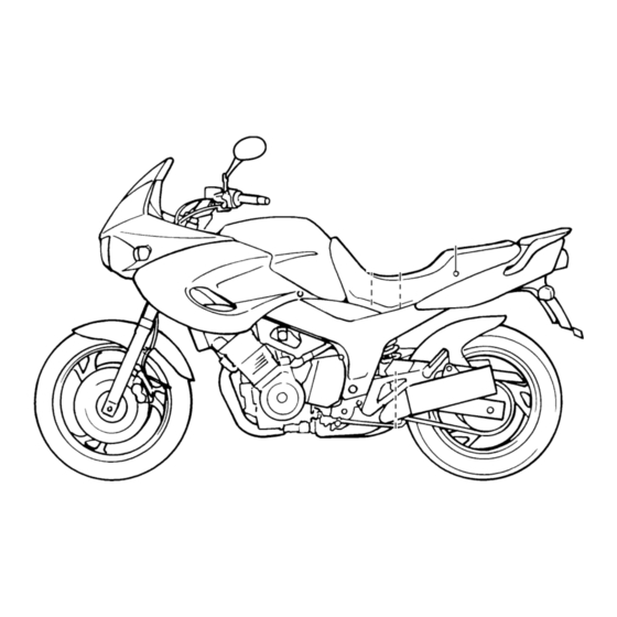
Page 10: Description
DESCRIPTION Left view ..................... 2-1 Right view................... 2-2 Controls/Instruments ................2-3... - Page 11 D ESCRIPTION EAU00026 Left view 1. Coolant reservoir tank (page 6-10) 2. Helmet holder (page 3-13) 3. Seat lock (page 3-12) 4. Rear shock absorber spring preload adjusting nut (for fine adjustment) (page 3-15) 5. Rear shock absorber damping force adjusting knob (page 3-16)
- Page 12 DESCRIPTION Right view 6. Luggage strap holders (page 3-17) 7. Rear shock absorber spring preload adjusting lever (for coarse adjustment) (page 3-15) 8. Fuses (page 6-29) 9. Engine oil level check window (page 6-8) 10. Front fork spring preload adjusting bolt (page 3-14) 11.
- Page 13 DESCRIPTION Controls/Instruments 12. Clutch lever (page 3-8) 17. Tachometer (page 3-4) 13. Handlebar switches (page 3-6) 18. Fuel gauge (page 3-5) 14. Starter (choke) “ ” (page 3-7) 19. Throttle grip (page 6-16) 15. Speedometer (page 3-3) 20. Front brake lever (page 3-9) 16.
-
Page 14: Instrument And Control Functions
INSTRUMENT AND CONTROL FUNCTIONS Main switch/steering lock ........3-1 Rear brake pedal..........3-9 Indicator lights ............3-2 Fuel tank cap ............. 3-10 Speedometer ............3-3 Fuel ..............3-11 Tachometer ............3-4 Fuel tank breather hose (for Germany only) ..3-12 Diagnosis device...........3-5 Seat..............3-12 Antitheft alarm (optional) ........3-5 Helmet holder............. -
Page 15: Main Switch/Steering Lock
I NSTRUMENT AND CONTROL FUNCTIONS EAU00027 1. Push 2. Turn EAU00029* EAU00040 Main switch/steering lock LOCK EW000016 The steering is locked in this position WARNING The main switch controls the ignition and all electrical circuits are switched and lighting systems. Its operation is Never turn the key to “OFF”... -
Page 16: Indicator Lights
Do not use this position for an extend- when the turn switch is moved to the while pushing the start switch, have a ed length of time as the battery may left or right. Yamaha dealer inspect the electrical discharge. circuit. EAU00061 EC000002 Neutral indicator light “... -
Page 17: Speedometer
When set to “ODO”, the motorcycle’s an odometer while pushing the start switch, have a total mileage is indicated. two trip odometers Yamaha dealer inspect the electrical When set to “TRIP 1” or “TRIP 2”, the a clock circuit. motorcycle’s mileage since the trip meter was last reset is indicated. -
Page 18: Tachometer
INSTRUMENT AND CONTROL FUNCTIONS Selecting a mode To set the clock Push the “SELECT” button to change 1. Push both the “SELECT” and between the odometer mode “ODO” “RESET” buttons for at least two and the trip odometer modes “TRIP 1”, seconds. -
Page 19: Diagnosis Device
Yamaha dealer for repair. needle indicates “E” (Empty), about EC000004 CAUTION: 3.1 L remain in the fuel tank. To prevent engine damage, be sure to consult a Yamaha dealer as soon as possible if the tachometer dis- plays a repeated change in r/min. -
Page 20: Handlebar Switches
INSTRUMENT AND CONTROL FUNCTIONS EAU00127 EAU00144 Turn signal switch Hazard switch “ ” To signal a right-hand turn, push the The hazard switch should be turned on switch to “ ”. To signal a left-hand under emergency or hazardous condi- turn, push the switch to “... -
Page 21: Starter (Choke)
INSTRUMENT AND CONTROL FUNCTIONS EAU00143 Start switch “ ” The starter motor cranks the engine when pushing the start switch. EC000005 CAUTION: See starting instructions prior to starting the engine. 1. Engine stop switch 1. Starter (choke) “ ” 2. Lights switch EAU02976 3. -
Page 22: Description
INSTRUMENT AND CONTROL FUNCTIONS 1. Clutch lever 1. Shift pedal EAU00152 EAU00157 Clutch lever Shift pedal The clutch lever is located on the left This motorcycle is equipped with a con- handlebar, and the ignition circuit cut- stant-mesh 5-speed transmission. off system is incorporated in the clutch The shift pedal is located on the left lever holder. -
Page 23: Front Brake Lever
INSTRUMENT AND CONTROL FUNCTIONS 1. Brake lever position adjuster 1. Adjusting nut 1. Rear brake pedal a. Lever distance 2. Proper position EAU00162 Rear brake pedal To adjust the front brake lever position, EAU00160 Front brake lever The rear brake pedal is on the right turn the adjusting nut while pulling the The front brake lever is located on the side of the motorcycle. -
Page 24: Fuel Tank Cap
INSTRUMENT AND CONTROL FUNCTIONS NOTE: This tank cap cannot be closed unless the key is in the lock. The key cannot be removed if the cap is not locked properly. EW000023 WARNING Be sure the cap is properly installed and locked in place before riding the 1. -
Page 25: Fuel
INSTRUMENT AND CONTROL FUNCTIONS EAU00186 NOTE: CAUTION: If knocking or pinging occurs, use a dif- Always wipe off spilled fuel im- ferent brand of gasoline or higher oc- tane grade. mediately with a dry and clean soft cloth. Fuel may deteriorate painted surfaces plastic... -
Page 26: Fuel Tank Breather Hose (For Germany Only)
INSTRUMENT AND CONTROL FUNCTIONS 1. Fuel tank breather hose 1. Open 1. Projection ( 2) 2. Seat holder ( 2) EAU00196 EAU01726 Fuel tank breather hose Seat To install (for Germany only) To remove Insert the projections on the front of the Insert the key in the lock and turn it seat into the seat holders. -
Page 27: Helmet Holder
This compartment is designed to store Remove the seat and hook the helmet be sure to put them in a vinyl bag so a genuine Yamaha U-LOCK. (Other on the helmet holder. Then, reinstall they do not get wet. When washing the locks may not fit.) -
Page 28: Front Fork Adjustment
INSTRUMENT AND CONTROL FUNCTIONS Adjusting spring preload Turn the adjusting bolt in direction a to in- crease spring preload and in direction b to decrease spring preload. CI-18E Soft Standard Hard Adjusting position 1. Spring preload adjusting bolt 1. Damping force adjusting screw 2. -
Page 29: Rear Shock Absorber Adjustment
INSTRUMENT AND CONTROL FUNCTIONS 1. Adjusting lever 1. Locknut a. Distance “A” 2. Adjusting nut EAU01768* Rear shock absorber Spring preload: Fine adjustment (bottom) Minimum (soft): adjustment Proceed as follows to suit road condi- Distance “A” = 59 mm tions and the rider’s preference. This shock absorber is equipped with Standard: 1. - Page 30 * From the fully turned-in position cylinder in any way. Cylinder EC000015 damage will result in poor CAUTION: damping performance. Never attempt to turn an adjuster Take your shock absorber to a beyond the maximum or minimum Yamaha dealer for any service. setting. 3-16...
-
Page 31: Luggage Strap Holders
ENGINE WILL START. sponsibility retracting sidestand. Please check carefully CLUTCH SWITCH IS OK. the operating instructions listed be- low and if there is any indication of a malfunction, return the motorcycle to a Yamaha dealer immediately for repair. 3-17... - Page 32 INSTRUMENT AND CONTROL FUNCTIONS CD-11E SIDESTAND IS DOWN. ENGINE WILL STALL. SIDESTAND SWITCH IS OK. EW000045 WARNING If improper operation is noted, con- sult a Yamaha dealer immediately. 3-18...
-
Page 34: Pre-Operation Checks
PRE-OPERATION CHECKS Pre-operation check list..............4-1... -
Page 35: Pre-Operation Check List
P RE-OPERATION CHECKS EAU01114 Owners are personally responsible for their vehicle’s condition. Your motorcycle’s vital functions can start to deteriorate quickly and unexpectedly, even if it remains unused (for instance, if it is exposed to the elements). Any damage, fluid leak or loss of tire pressure could have serious consequences. - Page 36 PRE-OPERATION CHECKS ITEM CHECKS PAGE Brake and clutch lever • Check for smooth operation. 6-25 pivots • Lubricate if necessary. • Check for smooth operation. Sidestand pivot 6-26 • Lubricate if necessary. • Make sure that all nuts, bolts and screws are properly tightened. Chassis fasteners —...
-
Page 38: Operation And Important Riding Points
OPERATION AND IMPORTANT RIDING POINTS Starting the engine................5-1 Starting a warm engine ..............5-4 Shifting ....................5-4 Tips for reducing fuel consumption ............ 5-5 Engine break-in .................. 5-5 Parking ....................5-6... -
Page 39: Starting The Engine
The engine their functions. Consult can be started only under one of the Yamaha dealer regarding any following conditions: control or function that you do The transmission is in neutral. not thoroughly understand. The sidestand is up, the transmis-... - Page 40 OPERATION AND IMPORTANT RIDING POINTS CF-28E TURN THE MAIN SWITCH TO “ON” AND THE ENGINE STOP SWITCH TO “ ”. IF TRANSMISSION IS IN NEUTRAL AND IF TRANSMISSION IS IN GEAR AND SIDESTAND IS DOWN, SIDESTAND IS UP, PUSH THE START SWITCH. PULL IN THE CLUTCH LEVER AND PUSH THE ENGINE WILL START.
- Page 41 Yamaha deal- 4. Start the engine by pushing the 6. After the engine is warm, turn off er check the monitoring circuits. If start switch.
-
Page 42: Starting A Warm Engine
OPERATION AND IMPORTANT RIDING POINTS EAU01258 EC000048 Starting a warm engine CAUTION: The starter (choke) is not required Do not coast for long periods when the engine is warm. with the engine off, and do not EC000046 tow the motorcycle a long dis- CAUTION: tance. -
Page 43: Tips For Reducing Fuel Consumption
OPERATION AND IMPORTANT RIDING POINTS EAU00424 EAU00436 EAU00440 Tips for reducing fuel Engine break-in 0 ~ 150 km Avoid operation above 5,000 r/min. consumption There is never a more important period Stop the engine and let it cool for 5 to in the life of your motorcycle than the Your motorcycle’s fuel consumption 10 minutes after every hour of opera-... -
Page 44: Parking
If any engine trouble should oc- WARNING cur during the break-in period, The exhaust system is hot. Park the consult a Yamaha dealer imme- motorcycle in a place where pedes- diately. trians or children are not likely to touch the motorcycle. Do not park the motorcycle on a slope or soft ground;... -
Page 46: Periodic Maintenance And Minor Repair
PERIODIC MAINTENANCE AND MINOR REPAIR Tool kit..............6-1 Drive chain slack check........6-23 Periodic maintenance and lubrication....6-2 Drive chain slack adjustment ......6-23 Cowling and panel removal and installation..6-5 Drive chain lubrication........6-24 Cowlings A and B ..........6-5 Cable inspection and lubrication ......6-24 Panels A and B .............6-6 Throttle cable and grip lubrication ...... -
Page 47: Tool Kit
If you do not have necessary tools re- brication will keep your motorcycle in quired during a service operation, take the safest and most efficient condition your motorcycle to a Yamaha dealer for possible. Safety is an obligation of the service. motorcycle owner. The maintenance... -
Page 48: Periodic Maintenance And Lubrication
PERIODIC MAINTENANCE AND MINOR REPAIR EAU00473 PERIODIC MAINTENANCE AND LUBRICATION CP-01E EVERY 6,000 km 12,000 km INITIAL ITEM CHECKS AND MAINTENANCE JOBS (1,000 km) 6 months 12 months (whichever (whichever comes first) comes first) • Check fuel hoses for cracks or damage. Fuel line •... - Page 49 PERIODIC MAINTENANCE AND MINOR REPAIR EVERY 6,000 km 12,000 km INITIAL ITEM CHECKS AND MAINTENANCE JOBS (1,000 km) 6 months 12 months (whichever (whichever comes first) comes first) • Check swingarm pivoting point for play. • Correct if necessary. Swingarm •...
- Page 50 Cooling system • Correct if necessary. • Change coolant every 24,000 km or 24 months (whichever comes first). * Since these items require special tools, data and technical skills, they should be serviced by a Yamaha dealer. EAU02970* NOTE: The air filter needs more frequent service if you are riding in unusually wet or dusty areas.
-
Page 51: Cowling And Panel Removal And Installation
PERIODIC MAINTENANCE AND MINOR REPAIR 1. Cowling A 1. Cowling B 1. Screw ( 3) 2. Panel A 2. Panel B EAU00484* Cowlings A and B EAU01139 Cowling and panel removal To remove and installation Remove the screws and pull outward The cowlings and panels illustrated as shown. -
Page 52: Panels A And B
PERIODIC MAINTENANCE AND MINOR REPAIR 1. Screw 1. Spark plug cap 1. Spark plug wrench Inspection EAU01691* EAU01668* Panels A and B Spark plugs The spark plug is an important engine To remove Removal component and is easy to inspect. The 1. - Page 53 Do not attempt to diagnose such prob- Tightening torque: lems yourself. Instead, take the motor- Spark plug: cycle to a Yamaha dealer. You should 18 Nm (1.8 m·kg) periodically remove and inspect the spark plugs because heat and deposits NOTE:...
-
Page 54: Engine Oil
PERIODIC MAINTENANCE AND MINOR REPAIR 1. Engine oil drain bolt a 1. Oil level window 1. Engine oil filler cap 2. Minimum level mark 2. The oil tank is located behind the Engine oil and oil filter element re- 3. Maximum level mark engine cylinders. - Page 55 PERIODIC MAINTENANCE AND MINOR REPAIR Recommended oil: See page 8-1. Oil quantity: Total amount: 4.2 L Periodic oil change: 3.5 L With oil filter replacement: 1. Engine oil drain bolt b 3.6 L 1. Oil filter 2. Oil filter cover bolt ( 5) 2.
-
Page 56: Cooling System
PERIODIC MAINTENANCE AND MINOR REPAIR 8. Start the engine and warm up for a few minutes. While warming up, check for oil leakage. If oil leakage is found, stop the engine immedi- ately and check for the cause. 9. Stop the engine and check the oil level. -
Page 57: Changing The Coolant
PERIODIC MAINTENANCE AND MINOR REPAIR NOTE: If water is added, have a Yamaha dealer check the antifreeze con- tent of the coolant as soon as pos- sible. The radiator fan operation is com- pletely automatic. It is switched on or off according to the coolant tem- perature in the radiator. - Page 58 7. Remove the coolant reservoir by 17. Check for coolant leakage. If any Recommended antifreeze: removing the bolts. leakage is found, ask a Yamaha High quality ethylene glycol 8. Remove the coolant reservoir dealer to inspect the cooling sys- antifreeze containing corrosion hose clamp and disconnect the tem.
-
Page 59: Air Filter
PERIODIC MAINTENANCE AND MINOR REPAIR 1. Bolt ( 2) 1. Fuel sender coupler 1. Fuel cock 2. Fuel hose 4. Disconnect the fuel sender cou- EAU01769* 3. Breather hose Air filter pler. The air filter should be cleaned at the 5. - Page 60 PERIODIC MAINTENANCE AND MINOR REPAIR 1. Air filter case cover 1. Air filter 2. Screw ( 3) 7. Remove the air filter. 8. Tap the air filter lightly to remove 6. Remove the air filter case cover by most of the dust and dirt. Blow out removing the screws.
-
Page 61: Carburetor Adjustment
Most adjustments The engine should never be run should be left to a Yamaha dealer who without the air filter installed. has the professional knowledge and Excessive piston and/or cylin- experience to do so. -
Page 62: Throttle Cable Free Play Inspection
Yamaha service technician. a. Free play EAU00635 Throttle cable free play inspection There should be a free play of 3 ~ 5 mm at the throttle grip. If the free play is incorrect, ask a Yamaha dealer to make this adjustment. 6-16... -
Page 63: Tires
PERIODIC MAINTENANCE AND MINOR REPAIR EAU00658 CE-33E EW000083 Maximum load* 203 kg Tires WARNING Cold tire pressure Front Rear To ensure maximum performance, Proper loading of your motorcycle 225 kPa 275 kPa long service and safe operation, note Up to 90 kg load* (2.25 kg/cm (2.75 kg/cm is important for several characteris-... - Page 64 Brakes, tires, and relat- can be given if tire combina- ed wheel parts replacement should tions other than what is ap- 1. Side wall be left to a Yamaha Service Techni- proved used this a. Tread depth cian.
-
Page 65: Clutch Lever Free Play Adjustment
PERIODIC MAINTENANCE AND MINOR REPAIR EAU00684 WARNING This motorcycle is fitted with super high-speed running tires. The fol- lowing points must be observed in order for you to make fully effective use of these tires. Never fail to use the specified tires in tire replacement. -
Page 66: Rear Brake Pedal Height Adjustment
Rear brake pedal height Yamaha dealer inspect and bleed adjustment the system if necessary. The top of the brake pedal should be positioned 29 mm below the top of the footrest. If not, ask a Yamaha dealer to adjust it. 6-20... -
Page 67: Brake Light Switch Adjustment
ALMOST in contact with the disc turning the adjusting nut. plate, ask a Yamaha dealer to replace Turn the adjusting nut in direction a to the pads. make the brake light come on earlier. -
Page 68: Inspecting The Brake Fluid Level
1. Minimum level mark 1. Minimum level mark Have a Yamaha dealer check the When checking the fluid level, EAU00731 cause if the brake fluid level goes Inspecting the brake fluid make sure the top of the master down. -
Page 69: Brake Fluid Replacement
EAU00742 Brake fluid replacement The brake fluid should be replaced only by trained Yamaha service personnel. Have the Yamaha dealer replace the following components during periodic maintenance or when they are dam- aged or leaking: oil seals (every two years) a. -
Page 70: Drive Chain Lubrication
Yamaha dealer to replace it. Wipe it dry, and thoroughly lubricate it Keep the slack within the specified with SAE 30 ~ 50W motor oil. Do not limits. -
Page 71: Throttle Cable And Grip Lubrication
PERIODIC MAINTENANCE AND MINOR REPAIR EAU00773 EAU02984 EAU02985 Throttle cable and grip Brake and shift pedal Brake and clutch lever lubrication lubrication lubrication The throttle twist grip assembly should Lubricate the pivoting parts. Lubricate the pivoting parts. be greased at the time that the cable is lubricated, since the grip must be re- Recommended lubricant: Recommended lubricant:... -
Page 72: Sidestand Lubrication
Lubricate the pivoting parts. and metal-to-metal contact surfaces. Check that the sidestand moves up Recommended lubricant: and down smoothly. Molybdenum disulfide grease Recommended lubricant: Engine oil EW000113 WARNING If the sidestand does not move smoothly, consult a Yamaha dealer. 6-26... -
Page 73: Front Fork Inspection
If EC000098 any free play can be felt, ask a Yamaha CAUTION: dealer to inspect and adjust the steer- If any damage or unsmooth move- ing. -
Page 74: Wheel Bearings
Therefore it is not dangerous, causing severe burns, smoothly, have a Yamaha dealer in- necessary to check the electrolyte or fill etc. It contains sulfuric acid. Avoid spect the wheel bearings. -
Page 75: Fuse Replacement
Install a new fuse of specified amperage. Turn on the switches and see if the electrical device operates. If the fuse immediately blows again, con- sult a Yamaha dealer. 6-29... -
Page 76: Headlight Bulb Replacement
PERIODIC MAINTENANCE AND MINOR REPAIR Specified fuses: Main fuse: 30 A Headlight fuse: 15 A Signaling system fuse: 15 A Ignition fuse: 10 A Hazard light fuse: 10 A Odometer fuse: Radiator fan fuse: 7.5 A 1. Bulb holder cover 1. -
Page 77: Tail/Brake Light Bulb Replacement
PERIODIC MAINTENANCE AND MINOR REPAIR 4. Install the bulb holder cover and reconnect the headlight connec- tors. If the headlight beam adjust- ment is necessary, ask a Yamaha dealer to make that adjustment. 1. Screw ( 2) 1. Bulb ( 2) 2. -
Page 78: Turn Signal Light Bulb Replacement
EAU01095 If your motorcycle requires any repair, Turn signal light bulb bring it to a Yamaha dealer. The skilled replacement technicians at a Yamaha dealership 1. Remove the screw and the lens. have the tools, experience, and know- 2. -
Page 79: Troubleshooting Chart
Remove spark plugs and check electrodes. Engine doesn’t start, go to battery Dry. Ask a Yamaha dealer to inspect. check. 4. Battery Engine turns over Battery good. quickly. Engine doesn’t start, ask a Yamaha Use the electric starter. -
Page 80: Engine Overheating
Restart the engine. If the engine overheats again, ask a Level is OK. Yamaha dealer to inspect and repair the cooling system. NOTE: If it is difficult to get the recommended coolant, tap water can be temporarily used, provided that it is changed to the recom- mended coolant as soon as possible. -
Page 82: Motorcycle Care And Storage
MOTORCYCLE CARE AND STORAGE Care ....................7-1 Storage....................7-4... - Page 83 M OTORCYCLE CARE AND STORAGE EAU01517 Care Before cleaning Cleaning 1. Cover up the muffler outlets with After normal use The exposure of its technology makes a plastic bags. Remove dirt with warm water, a neutral motorcycle charming but also vulnera- 2.
- Page 84 MOTORCYCLE CARE AND STORAGE ECA00010 Do not use any harsh chemical For motorcycles equipped with CAUTION: products on plastic parts. Be a windshield: Do not use strong Avoid using strong acidic wheel sure to avoid using cloths or cleaners or hard sponges as cleaners, especially on spoked sponges which have been in they...
- Page 85 MOTORCYCLE CARE AND STORAGE 1. Clean your motorcycle with cold After cleaning EWA00001 WARNING water and soap after the engine 1. Dry the motorcycle with a chamois Make sure that there is no oil or wax has cooled down. or an absorbing cloth. on the brakes and tires.
- Page 86 NOTE: “OFF” position: Turn the fuel cock To prevent corrosion, avoid Consult a Yamaha dealer for advice on to “OFF”. damp cellars, stables (because what products to use. 4. Fill up the fuel tank and add fuel...
- Page 87 MOTORCYCLE CARE AND STORAGE a. Remove the spark plug caps and 6. Lubricate all control cables and 9. Remove the battery and fully spark plugs. the pivoting points of all levers and charge it. Store it in a cool, dry b.
-
Page 88: Specifications
SPECIFICATIONS Specifications ..................8-1 HOW TO USE THE CONVERSION TABLE ........8-5... -
Page 89: Specifications
S PECIFICATIONS EAU01038 Specifications Model TDM850 Engine oil Dimensions Type -20˚ -10˚ 0˚ 10˚ 20˚ 30˚ 40˚ 50˚C Overall length 2,165 mm (for GB, NL, B, F, E, P , I, GR, D, SAE 10W/30 SAE 10W/40 2,200 mm (for N, S, SF) - Page 90 SPECIFICATIONS Air filter Dry type element Gear ratio Fuel 2.643 Type Regular unleaded gasoline 1.947 Fuel tank capacity 20 L 1.500 Reserve amount 3.1 L 1.174 Carburetor 0.964 Type quantity BDSR38 Chassis Manufacturer MIKUNI Frame type Diamond Spark plug Caster angle 24.5°...
- Page 91 SPECIFICATIONS Maximum load* 203 kg Rear Air pressure (cold tire) Type Single disc brake Up to 90 kg load* Operation Right foot operation Front 225 kPa (2.25 kg/cm , 2.25 bar) Fluid DOT 4 Rear 275 kPa (2.75 kg/cm , 2.75 bar) Suspension 90 kg load ~ maximum Front...
- Page 92 SPECIFICATIONS Bulb voltage, wattage quantity Headlight 12 V, 55 W Auxiliary light 12 V, 5 W Tail/brake light 12 V, 5/21 W Turn signal light 12 V, 21 W Meter light 12 V, 2 W Neutral indicator light 14 V, 1.4 W High beam indicator light 14 V, 1.4 W Turn indicator light...
-
Page 93: How To Use The Conversion Table
SPECIFICATIONS EAU01064 HOW TO USE THE CONVERSION TABLE CS-02E CONVERSION TABLE All specification data in this manual are listed in SI and METRIC TO IMPERIAL METRIC UNITS. Metric unit Multiplier Imperial unit Use this table to convert METRIC unit data to IMPERIAL m·kg 7.233 ft·lb... -
Page 94: Consumer Information
CONSUMER INFORMATION Identification number records............. 9-1 Key identification number ..............9-1 Vehicle identification number.............. 9-1 Model label..................9-2... -
Page 95: Identification Number Records
Record the key identification number, vehicle identification number and mod- el label information in the spaces pro- vided for assistance when ordering spare parts from a Yamaha dealer or for reference in case the vehicle is sto- len. 1. Key identification number 1. -
Page 96: Consumer Information
The model label is affixed to the frame under the seat. (See page 3-12 for seat removal procedures.) Record the infor- mation on this label in the space pro- vided. This information will be needed to order spare parts from your Yamaha dealer. -
Page 97: Left View
I NDEX 1 0 - High beam indicator light......3-2 Horn switch ..........3-6 Air filter ..........6-13 Engine break-in ........5-5 Antitheft alarm (optional) ......3-5 Engine oil ..........6-8 Engine overheating......... 6-34 Identification number records ....9-1 Engine stop switch........3-7 Idle speed adjustment ......6-15 Battery ...........6-28 Indicator lights..........3-2 Brake and clutch lever lubrication...6-25... -
Page 98: Right View
INDEX Troubleshooting ........6-32 Troubleshooting chart ......6-33 Rear brake pedal ........3-9 Turn indicator lights......... 3-2 Rear brake pedal height adjustment ..6-20 Turn signal light bulb replacement..6-32 Rear shock absorber adjustment ... 3-15 Turn signal switch ........3-6 Rear suspension lubrication.... - Page 99 YAMAHA MOTOR CO., LTD. PRINTED ON RECYCLED PAPER PRINTED IN JAPAN 99 · 9 - 0.8...
Need help?
Do you have a question about the TDM850 and is the answer not in the manual?
Questions and answers
how do I check the level of coolant
To check the coolant level in a Yamaha TDM850:
1. Place the motorcycle on a level surface and hold it in an upright position.
2. Remove the right-hand fairing to access the radiator pressure cap and filler.
3. Check that the coolant level is within the specified range.
4. If needed, add coolant to the correct level.
5. Ensure the radiator is not damaged or blocked over more than 30% of its surface area.
This answer is automatically generated
coolant level check
To check the coolant level on a Yamaha TDM850:
1. Place the motorcycle on a level surface and hold it upright.
2. Look under the seat from the left-hand side of the rear wheel to see the coolant reservoir.
3. Check that the coolant level is between the FULL and LOW markings on the reservoir.
4. If the level is low, remove the seat, then remove the reservoir filler cap.
5. Add the recommended coolant mixture until it reaches the proper level.
6. Secure the cap and reinstall the seat.
This answer is automatically generated