Advertisement
IMPORTANT: Refer to the
instructions inside when
converting this grill to
Natural Gas.
© 2011 Char-Broil, LLC Columbus, GA 31902
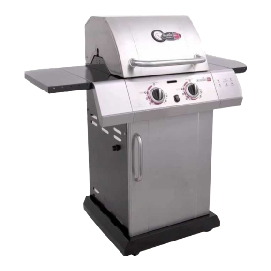
PRODUCT GUIDE
MODEL 463250212
T-22D
IMPORTANT: Fill out the product record information below.
Serial Number
Date Purchased
For support and to register your
grill, please visit us at
www.charbroil.com
If you have questions or need
assistance during assembly,
please call 1-888-430-7870.
Printed in China
See rating label on grill for serial number.
Assembly instructions © 2011
08/16/11 • G352-001-040801
Advertisement
Table of Contents

Related Manuals for Char-Broil 463250212


Summary of Contents for Char-Broil 463250212
- Page 1 PRODUCT GUIDE MODEL 463250212 T-22D IMPORTANT: Fill out the product record information below. Serial Number See rating label on grill for serial number. Date Purchased For support and to register your grill, please visit us at www.charbroil.com If you have questions or need assistance during assembly, please call 1-888-430-7870.
-
Page 2: Table Of Contents
TABLE OF CONTENTS DANGER For Your Safety ........2-3 If you smell gas: Use and Care . - Page 3 WARNING CAUTION CALIFORNIA PROPOSITION 65 Using pots larger than 6 quarts in capacity could exceed weight limit of the 1. Combustion by-products produced when using this product contain chemicals known to the State of side burner shelf California to cause cancer, birth defects, and other or side shelf, reproductive harm.
-
Page 4: Use And Care
LP Cylinder USE AND CARE •The LP cylinder used with your grill must meet the following requirements: DANGER •Use LP cylinders only with these required measurements: 12" (30.5cm) (diameter) x 18" (45.7 cm) (tall) with 20 lb. (9 kg.) capacity maximum. •... -
Page 5: For Your Safety
LP Cylinder Exchange Connecting Regulator to the LP Cylinder •Many retailers that sell grills offer you the option of replacing 1.LP cylinder must be properly secured onto grill. (Refer to your empty LP cylinder through an exchange service. Use only assembly section.) those reputable exchange companies that inspect, precision fill, 2.Turn all control knobs to the OFF position. - Page 6 Leak Testing Valves, Hose and Regulator 1.Turn all grill control knobs to OFF. 2.Be sure regulator is tightly connected to LP cylinder. 3.Completely open LP cylinder valve by turning hand wheel counterclockwise. If you hear a rushing sound, turn gas off immediately.
- Page 7 Safety Tips WARNING Before opening LP cylinder valve, check the coupling nut for tightness. When grill is not in use, turn off all control knobs and LP For Safe Use of Your Grill and to Avoid Serious cylinder valve. ...
- Page 8 Burner Flame Check WARNING •Remove cooking grates and troughs. Light burners, rotate knobs from . You should see a smaller flame in Turn controls and gas source or tank OFF when not position than seen on . Always check flame prior to in use.
-
Page 9: Spider Alert
Cleaning the Burner Assembly CAUTION Follow these instructions to clean and/or replace parts of burner assembly or if you have trouble igniting grill. 1. Turn gas OFF at control knobs and LP cylinder. SPIDER ALERT! 2. Remove cooking grates and troughs. 3. -
Page 10: Limited Warranty
LIMITED WARRANTY This warranty only applies to units purchased from an authorized retailer. Manufacturer warrants to the original consumer-purchaser only that this product shall be free from defects in workmanship and materials after correct assembly and under normal and reasonable home use for the periods indicated below beginning on the date of purchase*. -
Page 11: Parts List
PARTS LIST NOT Pictured Key Qty Description TOP LID Key Qty Description BEZEL, F/ LID HANDLE … DOOR MAGNET HANDLE F/ TOP LID … CASTER PIN LOGO PLATE, TEMP GAUGE … HARDWARE PACK RUBBER BUMPER, RECTANGLE, F/ TOP … ASSEMBLY MANUAL, ENGLISH …... -
Page 12: Parts Diagram
PARTS DIAGRAM... -
Page 13: Assembly
ASSEMBLY Place bottom shelf upside down. Insert Caster Pin into the caster mounting plate to lock it in place, shown A. Spin the caster clockwise into the threads on the bottom shelf until secure. Remove the Caster Pin and repeat for remaining casters. - Page 14 This step requires two people to lift and position grill head onto cart. Untie regulator hose which is factory bundled underneath the grill head. Carefully lower the grill head onto the cart, aligning slots at bottom of grill head with posts on cart side panels. Make sure regulator hose is hanging inside the cart.
- Page 15 Note: DO NOT over tighten screws and washers that come into contact with porcelain coated surfaces. Over tightening may cause the porcelain coating to crack and break, resulting in exposed metal that will be prone to rust. Insert front brace under control panel and between cart side panels, oriented as shown. Secure upper holes using one 1/4-20x1½”...
- Page 16 Attach foldable side shelf brackets to the slots in the tracks under right side shelf using one shoulder screw and 1/4” nut each side, shown A/B. Pull foldable side shelf outward and press it down, shown C. Push foldable side shelf toward right side shelf untill they meet, shown D. Only right side shelf shown for assembly, repeat above steps to Install left side shelf with foldable side shelf.
- Page 17 On back of grill, place upper back panel between side panels. Upper back panel should be oriented with slots on the bottom. Secure upper back panel, in lower holes, using one 1/4-20x1½” screw on each side. Upper back panel 1/4-20x1½” screw slots on the bottom...
- Page 18 Insert flange on right side shelf into side shelf brackets on side of firebox, shown A. Attach right side shelf using two 1/4-20x3/4” screws and 1/4” nut, shown B. Attach front of shelf using three #8x3/8” self-tapping screws and large flat washers, shown C. Note: For ease of assembly, use a long-blade screw driver for this step.
- Page 19 Inside of cart, insert rear tabs (w/o holes) of tank heat shield into slots on the bottom of upper back panel. Attach front tabs (w/ holes) of tank heat shield under front brace using two #8x3/8” self-tapping screws. Front brace #8x3/8”...
- Page 20 Attach door handle to door using two #10-24x3/8” screws, 5mm lock washers and 5mm flat washers, shown A. Insert hinge pin on bottom of door into hole in bottom shelf. Press upper hinge pin in front brace, align hinge hole on top of door, and release hinge pin into door.
- Page 21 Place cooking grates onto the firebox as shown. Insert the three wire ends at rear of warming rack into holes in back of firebox. Front wires of warming rack rest on sides of firebox. Assembled warming rack Warming rack Cooking grate LP TANK IS SOLD SEPARATELY.
-
Page 22: Conversion Instructions
Consumer must purchase Natural Gas Conversion Kit 4584625 to convert this grill to natural gas. Use the following instructions instead of instructions found in conversion kit Main Burner Conversion Make sure all Control Knobs are in the OFF position, LP Tank Valve is closed, Tank is disconnected from Regulator and removed from Grill. - Page 23 Pull the Burner Control Knobs off of Valve Stems. Remove Screws and Washers that secure each Bezel to the Control Panel. Save removed Bezels for converting back to LP Tank Gas. Install new Natural Gas Bezels provided with Kit (see illustration below) in place of old Bezels, on Control Panel and secure using previously removed Screws and Washers.
- Page 24 Natural Gas Hose Conversion Using a wrench, not provided, remove LP Regulator Hose Assembly from Manifold Connection. Save removed LP Manifold Connection for converting back to LP Tank Gas. Your Grill may differ from illustration shown. Manifold Connection LP Regulator Hose Assembly Manifold Connection Natural Gas Hose Assembly...
- Page 25 4. When the quick disconnect socket and the gas hose are connected, WARNING a valve in the socket opens automatically to permit full gas flow. When the gas hose is disconnected, the valve in the socket instantly and positively shuts off the flow of gas. Because the valve in the Do not use hard metal piping of any kind to connect this socket positively shuts off the flow of gas, the grill can be type of grill to natural gas source.
-
Page 26: Troubleshooting
DANGER: If a gas leak cannot be stopped, or a fire occurs due to gas leakage, call the fire department. Emergencies Possible Cause Prevention/Solution Gas leaking from • Damaged hose. • Turn off gas at LP cylinder or at source on natural gas systems. If cracked/cut/burned anything but burned, replace valve/hose/regulator. - Page 27 Troubleshooting (continued) Problem Possible Cause Prevention/Solution Burner(s) will not light ELECTRONIC IGNITION: using ignitor. • No spark, no ignition noise. • See Section I of Electronic Ignition System. (See Electronic Ignition Troubleshooting also) • No spark, some ignition noise. • See Section II of Electronic Ignition System. •...
- Page 28 Troubleshooting - Electronic Ignition Problem (Ignition) Possible Cause Check Procedure Prevention/Solution SECTION I No sparks appear at • Battery not installed • Check battery orientation. • Install battery (make sure that “+” and “–” any electrodes when properly. connectors are oriented correctly, with “+” end up Electronic Ignition Button and “–”...
- Page 29 NOTES...
- Page 30 NOTES...