
Related Manuals for AOpen AX59PRO


Summary of Contents for AOpen AX59PRO
- Page 1 AX59PRO User's Guide Printed in Taiwan PART NO.:49.87801.311 DOC. NO.:AX59P-1-E9903G...
- Page 2 AX59PRO Mainboard User's Guide Document Number : AX59P-1-E9809F Model and Revision : For AX59PRO revision 1.xx Manual Revision : English, revision F Release Date : Sep 21, 1998 More help for latest information: Taiwan http://www.aopen.com.tw http://www.aopen-usa.com http://www.aopenusa.com http://www.aopenamerica.com Europe http://www.aopen.nl...
- Page 3 Copyright Copyright © 1998 by this company. All rights reserved. No part of this publication may be reproduced, transmitted, transcribed, stored in a retrieval system, or translated into any language or computer language, in any form or by any means, electronic, mechanical, magnetic, optical, manual or otherwise, without the prior written permission of this company.
- Page 4 Disclaimer This company makes no representations or warranties, either expressed or implied, with respect to the contents hereof and specifically disclaims any warranties, merchantability or fitness for any particular purpose. Any software described in this manual is sold or licensed "as is". Should the programs prove defective following their purchase, the buyer (and not this company, its distributor, or its dealer) assumes the entire cost of all necessary servicing, repair, and any incidental or consequential damages resulting from any defect...
-
Page 5: Declaration Of Conformity
: FCC Class B Subassembly - CPU Board Type of Product : Intel Pentium PCI/ISA/AGP ATX Motherboard Chipset(s) : VIA MVP3 AX59PRO Test To Comply With FCC Standards FOR HOME OR OFFICE USE The limits of FCC Part 15 Class B are designed to provide reasonable protection against harmful interference in a residential installation. - Page 6 Notice 1: The changes or modifications not expressly approved by the party responsible for compliance could void the user's authority to operate the equipment. Notice 2: Shielded interface cables, if any, must be used in order to comply with emission limits.
-
Page 7: Overview
Organization Chapter 1, Overview, covers the introduction and specifications of the system board and special features. Chapter 2, Hardware Installation, describes hardware jumpers, connectors and memory configuration. There are user friendly drawings to locate jumper and connector. Chapter 3, AWARD BIOS, explains the system BIOS and tells how to configure the system by setting the BIOS parameters. - Page 8 Conventions The following conventions are used in this manual: Text entered user, Represent text input by the user, default default settings, settings and recommended selections recommended selections <Enter>, <Tab>,<Ctl>, <Alt>, Represent the actual keys that you <Ins>, <Del>, etc have to press on the keyboard. Note: Gives bits and pieces of additional information related to the current topic.
-
Page 9: Table Of Contents
Contents Chapter 1 Overview 1.1 Specifications..............3 1.2 Overclocking ..............5 1.3 Zero Voltage Modem Wake Up ........8 1.4 System Voltage Monitoring..........10 1.5 Fan Monitoring ..............10 1.6 CPU Thermal Protection ..........11 chapter 2 Hardware Installation 2.1 Jumper and Connector Locations ........2 2.2 Jumpers ................4 2.2.1 Setting the CPU Voltage...........5 2.2.2 Selecting the CPU Frequency ........8 2.2.3 DRAM Clock ............12... - Page 10 2.3.15 LAN Wake-up Connector........22 2.4 Configuring the System Memory.........23 2.5 Windows 98 Installation ..........29 chapter 3 Award BIOS 3.1 Entering the Award BIOS Setup Menu ......2 3.2 Standard CMOS Setup............3 3.3 BIOS Features Setup ............6 3.4 Chipset Features Setup..........11 3.5 Power Management Setup ...........15 3.6 PNP/PCI Configuration Setup........20 3.7 Load Setup Defaults .............23 3.8 Load Turbo Defaults .............23...
-
Page 11: Chapter 1 Overview
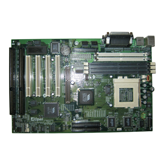
Chapter Overview AX59 Pro is a high-performance Pentium ® -based system board that utilizes VIA MVP3 AGPset on ATX PCI/ISA platform. This motherboard supports new architectures such as high speed AGP, SDRAM, Ultra DMA/33, Bus master IDE and USB port. It has 512KB or 1MB (optional) pipelined-burst second- level cache onboard and support two single in-line memory module (SIMM) plus three Dual in-line memory module (DIMM) that allows to mix EDO and SDRAM memory and expansion up to a maximum of 1GB. - Page 12 FCC DoC certificate AX59 Pro has passed FCC DoC test. The radiation is very low, you can use any kind of housing. Powerful utility software supported AOpen Bonus Pack companion CDROM contains many useful utilities, such as Norton Anti-virus, AOchip, Hardware...
-
Page 13: Specifications
Overview Specifications Form Factor 305 mm x 202 mm Board Size Intel Pentium Processor P54C, PP/MT (P55C), AMD K5/K6/K6-2, Cyrix 6x86/M2 and IDT WinChip C6 family. System Memory 72-pin SIMM x2, and SDRAM 168-pin x3, maximum 1GB. 512KB or 1MB (optional) pipeline-burst cache Second-level Cache onboard Chipset... - Page 14 Overview Special circuit (patent applied) to support modem Zero Voltage Modem wake up by external box modem or internal AOpen Wake Up F56/MP56 modem card. By using a network card that supports this feature LAN Wake Up and a network management software, you can wake up a system through a local area network.
-
Page 15: Overclocking
Overview Overclocking As a leading manufacturer in motherboard industry, AOpen always listens to what customers want and develop products to fit different user's requirements. Reliability, compatibility, leading technology and friendly features are our basic goals when designing motherboards. Other than above mentioned design criteria, there are power users who are always seeking to push the limitation of the system performance by overclocking which we call them "Overclocker". - Page 16 Overview VGA Card VGA model/ Vendor Chipset model Driver Asus S3 –Virge/dx(86c375) Asus VENUS T-775 S3 Trio 64V2(86C775) Venus VENUS 67TV Trident 9685 Venus GALAXIE Trident 9685 (PS-68) Venus MACH 64 210888GX00 Win95 default MATROX MY220P/4+ MATROX MGA-MIL/4+ MATROX MIL2P/4+ Hard Disk: Vender Model...
- Page 17 Overview AX59 Pro Overclocking Settings The following table lists the overclocking settings in AOpen’s lab for your reference. Intel MMX-233MHz SEC KOREA 801 DRAM KM48S2020CT-GH 32MB IBM DHEA-34330 ATI 3D RAGE PRO AGP 2X Windows 95 OSR2 R2.00d BIOS Load BIOS Setup Default for 112MHz * 2.5 = 280MHz (O.K.)
-
Page 18: Zero Voltage Modem Wake Up
Modem Wake Up, but if you use external modem, you have to keep the box modem always power-on. AOpen AX59 Pro and internal modem card implement special circuit (patent applied) and make sure the modem card works properly without any power. We recommend you choose AOpen modem card (MP56) for Modem Wake Up applications. - Page 19 Overview For Internal Modem Card (AOpen MP56): 1. Go into BIOS setup , Power Management Modem Wake Up, select Enable. 2. Setup your application, put into Windows 95. 3. Turn system power off by soft power switch. 4. Connect 4-pin Modem Ring-On cable from MP56 RING connector to AX59 Pro connector WKUP.
-
Page 20: System Voltage Monitoring
Overview System Voltage Monitoring This motherboard implements a voltage monitoring system. As you turn on your system, this smart design will continue to monitor your system working voltage. If any of the system voltage is over the component's standard. There will be alarm through application software such as Hardware Monitor utility for a warning to user. -
Page 21: Cpu Thermal Protection
Overview CPU Thermal Protection This motherboard implements special thermal protection circuit below the CPU. When temperature is higher than a predefined value, the CPU speed will automatically slow down and there will be warning from BIOS and also Hardware Monitoring Utility software. CPU Thermal Protection is automatically implemented by BIOS and utility software, no hardware installation is needed. -
Page 22: Chapter 2 Hardware Installation
Chapter Hardware Installation This chapter gives you a step-by-step procedure on how to install your system. Follow each section accordingly. Caution: Electrostatic discharge (ESD) can damage your processor, disk drives, expansion boards, and other components. Always observe the following precautions before you install a system component. -
Page 23: Jumper And Connector Locations
Hardware Installation 2.1 Jumper and Connector Locations The following figure shows the locations of the jumpers and connectors on the system board : BIOS COM2 COM1 PRINTER KB/PS2 IrDA SIMM2 SIMM1 PWR2 JP14 DIMM3 DIMM2 DIMM1 CPUFAN2 JP23 CPUFAN1 JP24 PANEL JP25 MODEM WKUP... - Page 24 Hardware Installation Jumpers: DIP Switch for CPU voltage and clock ratio SW1: JP4,JP5,JP6, CPU external (bus) clock JP25: DRAM Clock JP23,JP24 Clear CMOS JP14: Connectors: PS2: PS/2 mouse connector PS/2 keyboard connector COM1: COM1 connector COM2: COM2 connector PRINTER: Printer connector PWR2: ATX power connector USB:...
-
Page 25: Jumpers
Hardware Installation 2.2 Jumpers Jumpers are made by pin headers and plastic connecting caps for the purpose of customizing your hardware. Doing so requires basic knowledge of computer hardware, be sure you understand the meaning of the jumpers before you change any setting. -
Page 26: Setting The Cpu Voltage
Hardware Installation 2.2.1 Setting the CPU Voltage Vcore SW1 is used to select CPU core voltage (Vcore) and ratio, there 3.52V are totally eight switches on the 3.45V DIP. After installing CPU, set 3.2V the switch 4-8 to specify a proper Vcore. - Page 27 112MHz external clock while still conforming the design guide from VIA. This overclock scheme is accomplished by AOpen's technical expertise as well as manufacturing capabilities. However, please understand that some of the add-on cards might not work with this board properly when overclock scheme is engaged.
- Page 28 Hardware Installation This motherboard supports the CPU core voltage from 1.3V to 3.5V, that can be applied to the various CPU type in future. For your reference, all settings are listed in the following table. Vcore 1.30V 1.35V 1.40V 1.45V 1.50V 1.55V 1.60V...
-
Page 29: Selecting The Cpu Frequency
Hardware Installation 2.2.2 Selecting the CPU Frequency CPU Frequency Intel Pentium, Cyrix 6x86 and AMD K5/K6 CPU are designed Ratio to have different Internal (Core) 1.5x (3.5x) and External (Bus) frequency. The ratio of Core/Bus frequency 2.5x (1.75x) is selected by the switch 1-3 of SW1. - Page 30 Hardware Installation CPU CLK AGP CLK PCI CLK JP25 66MHz 66MHz 33MHz 68MHz 68MHz 34MHz 75MHz 75MHz 38MHz 83MHz 56MHz 28MHz 95MHz 64MHz 32MHz 100MHz 66MHz 33MHz 112MHz 75MHz 37MHz 124MHz 83Mhz 41MHz JP4, JP5, JP6 and J25 are the selections of CPU external clock (bus clock), AGP Clock and PCI Clock.
- Page 31 Hardware Installation 1 2 3 1 2 3 1 2 3 1 2 3 JP24 JP24 JP25 JP25 JP23 JP23 100MHz 124MHz 1 2 3 1 2 3 JP24 JP25 JP23 112MHz Warning: VIA MVP3 chipset supports maximum 100MHz external CPU bus clock, the 112MHz settings are for internal test only, set to 112 or 124 exceeds specification...
- Page 32 Hardware Installation INTEL CPU Core Ratio External JP4,JP5,JP6,JP25 Pentium Frequency Bus Clock P54C 100 100MHz = 1.5x 66MHz OFF OFF OFF 1-2 & 1-2 & 1-2 & 1-2 P54C 133 133MHz = 66MHz OFF OFF 1-2 & 1-2 & 1-2 & 1-2 P54C 166 166MHz = 2.5x...
-
Page 33: Dram Clock
Hardware Installation AMD K6 CPU Core Ratio External JP4,JP5,JP6,JP25 Frequency Bus Clock K6-166 166MHz = 2.5x 66MHz OFF 1-2 & 1-2 & 1-2 & 1-2 K6-200 200MHz = 66MHz OFF ON OFF 1-2 & 1-2 & 1-2 & 1-2 K6-233 233MHz = 3.5x 66MHz... -
Page 34: Clearing The Cmos
Hardware Installation 1 2 3 1 2 3 JP24 JP25 JP23 AGP CLK 2.2.4 Clearing the CMOS JP14 Clear CMOS You need to clear the CMOS if you forget your system password. To clear the Normal operation (default) CMOS, follow the procedures listed Clear CMOS below: JP14... -
Page 35: Connectors
Hardware Installation 2.3 Connectors 2.3.1 Power Cable The ATX power supply uses 20-pin connector shown below. Make sure you plug in the right direction. Caution: Make sure that the power supply is off before connecting or disconnecting the power cable. 3.3V 5V SB 3.3V... -
Page 36: Fan
Hardware Installation 2.3.3 Fan Plug in the fan cable to the fan connectors onboard. The fan connectors are marked CPUFAN1 , CPUFAN2 and FAN on the system board. You can plug the CPU fan cable to both the 2-pin fan connector CPUFAN1 and the 3-pin fan connector CPUFAN2. -
Page 37: Keyboard
Hardware Installation 2.3.5 Keyboard The onboard PS/2 keyboard connector is a 6-pin Mini-Din connector marked KB . The view angle of drawing shown here is from back panel of the housing. PS/2 KB 2.3.6 Serial Devices (COM1/COM2) The onboard serial connectors are 9-pin D-type connector on the back panel of mainboard. -
Page 38: Printer
Hardware Installation 2.3.7 Printer The onboard printer connector is a 25-pin D-type connector marked PRINTER . The view angle of drawing shown here is from back panel of the housing. PRINTER 2.3.8 USB Device You can attach USB devices to the USB connector. The mothermoard contains two USB connectors, which are marked as USB. -
Page 39: Ide Hard Disk And Cd Rom
Hardware Installation 2.3.10 IDE Hard Disk and CD ROM This motherboard supports two 40-pin IDE connectors marked as IDE1 and IDE2. IDE1 is also known as primary channel and IDE2 as secondary channel, each channel supports two IDE devices that makes total of four devices. In order to work together, the two devices on each channel must be set differently to master and slave mode, either one can be hard disk or CDROM. -
Page 40: Hard Disk Led
Hardware Installation IDE2 (Secondary Channel) Slave Master (4th) (3rd) IDE1 (Primary Channel) Slave Master (2nd) (1st) 2.3.11 Hard Disk LED Description The HDD LED connector is marked as HDD HDD LED LED on the board. This connector is designed for different type of housing, actually only two pins are necessary for the LED. -
Page 41: Panel Connector
Hardware Installation 2.3.12 Panel Connector The Panel (multifunction) connector is a 20- pin connector marked as PANEL on the board. Attach the power LED, keylock, KEYLOCK speaker, reset switch Reserved corresponding pins as shown in the figure. RESET POWER LED Some housings have a five-pin connector for SPEAKER the keylock and power LED Since power... -
Page 42: Irda Connector
Hardware Installation 2.3.13 IrDA Connector The IrDA connector can be configured to support wireless infrared module, with this module and application software such as Laplink or Win95 Direct Cable Connection, user can transfer files to or from laptops, notebooks, PDA and printers. This connector supports HPSIR (115.2Kbps, 2 meters), ASK-IR (56Kbps) and Fast IR (4Mbps, 2 meters). -
Page 43: Wake-Up Connector
Internal Modem card consumes no power when system RING power is off, it is recommended to use Internal Modem. To use AOpen MP56, connect 4-pin cable from RING connector of MP56 to WKUP connector on the mainboard. Tip: Not only for Modem Ring-On, there are many other possible applications. -
Page 44: Configuring The System Memory
Hardware Installation 2.4 Configuring the System Memory Pin1 This motherboard has two 72 pin SIMM sockets (Single-in-line Memory Module) and three 168 pin DIMM socket (Dual-in- line Memory Module) that allow you to Pin1 install system memory maximum 1GB. The SIMM supported by this mainboard can be identified by 4 kinds of factors: I. - Page 45 Hardware Installation II. Speed: normally marked as -12, which means the clock cycle time is 12ns and maximum clock of this SDRAM is 83MHz. Sometimes you can also find the SDRAM marked as -67, which means maximum clock is 67mhz. Caution: Some SDRAMs marked as -10 may work fine with 100 MHz CPU clock, but not all this kind of modules can work properly under...
- Page 46 Hardware Installation Caution: Note that DIMM3 shares a bank with SIMM1 and SIMM2, so you couldn't use a doulbe side DIMM if SIMMs were installed. Caution: There are some old DIMMs made by EDO or FPM memory chip, they can only accept 5V power and probably can not fit into the DIMM socket, make sure you have 3.3V true SDRAM DIMM before your insert it.
- Page 47 Hardware Installation Following table list the recommended DRAM combinations of SIMM and DIMM: SIMM SIMM Bit size Single/ Chip SIMM Recommended Data chip Parity chip per side Double count size side 1M by 4 None 1Mx32 1M by 4 None 1Mx32 1M by 4 1M by 1...
- Page 48 16M by 4 16Mx64 128MB For getting the best performance and stability under 100MHz or above external clock, we strongly recommend you use PC 100 SDRAM. The PC 100 SDRAM that AOpen had tested are listed below. Size Vendor Model Single/Double...
- Page 49 Hardware Installation Size Vendor Model Single/Double Chip Count Hyundai HY57V168010CTC-10 D4516821AG5-A10-7JF KM48S2020CT-GH Hyndai HY57V168010CTC-10 Micron MT48LC2M8A1-08 Fujitsu 81F16822D-A10-7JF Mitsubishi M5M4V64S30ATP -10 Fujitsu 81F64842B-103FN D4564841G5-A10-9JF KM48S8030BT-GH Toshiba TC59S6408FTL-80H Memory error checking is supported by parity check. To use parity check you need 36 bit SIMM (32 bit data + 4 bit parity), which are automatically detected by BIOS.
-
Page 50: Windows 98 Installation
Install the VIA IRQ routing driver, which will correct the partially wrong IRQ routing table for MVP3 chipset in Windows 98. Finally, Install other add-on cards. In the AOpen Bonus Pack CDROM, you can find above drivers in the path X:\Ax59pro\Driver (Where X: represents your CDROM drive). 2-29... -
Page 51: Chapter 3 Award Bios
Chapter Award BIOS This chapter tells how to configure the system parameters. You may update your BIOS via AWARD Flash Utility. Important: Because the BIOS code is the most often changed part of the mainboard design, the BIOS information contained this chapter (especially the Chipset Setup parameters) may be... -
Page 52: Entering The Award Bios Setup Menu
AWARD BIOS Entering the Award BIOS Setup Menu The BIOS setup utility is a segment of codes/routines residing in the BIOS Flash ROM. This routine allows you to configure the system parameters and save the configuration into the 128 byte CMOS area, (normally in the RTC chip or directly in the main chipset). -
Page 53: Standard Cmos Setup
AWARD BIOS 3.2 Standard CMOS Setup The "Standard CMOS Setup" sets the basic system parameters such as the date, time, and the hard disk type. Use the arrow keys to highlight an item and to select the value for each item. Standard CMOS Date To set the date, highlight the Date parameter. - Page 54 AWARD BIOS Standard CMOS Primary Master Type Standard CMOS Primary Slave Type Standard CMOS Secondary Master Type Standard CMOS Secondary Slave Type Type This item lets you select the IDE hard disk parameters that your system supports. These parameters are Size, Auto Number of Cylinder, Number of Head, Start Cylinder for User...
- Page 55 AWARD BIOS Standard CMOS Drive A Standard CMOS Drive B These items select floppy drive type. The available settings Drive A and types supported by the mainboard are listed on the left. None 360KB 5.25" 1.2MB 5.25" 720KB 3.5" 1.44MB 3.5" 2.88MB 3.5"...
-
Page 56: Bios Features Setup
AWARD BIOS 3.3 BIOS Features Setup This screen appears when you select the option "BIOS Features Setup" from the main menu. BIOS Features Virus Warning Virus Warning Set this parameter to Enabled to activate the warning message. This feature protects the boot sector and partition Enabled table of your hard disk from virus intrusion. - Page 57 AWARD BIOS BIOS Features External Cache External Cache Enabling this parameter activates the secondary cache (currently, PBSRAM cache). Disabling the parameter Enabled slows down the system. Therefore, we recommend that Disabled you leave it enabled unless you are troubleshooting a problem.
- Page 58 AWARD BIOS BIOS Features Boot Up NumLock Status Boot-up NumLock Setting this parameter to On enables the numeric function Status of the numeric keypad. Set this parameter to Off to disregard the function. Disabling the numeric function allows you to use the numeric keypad for cursor control. BIOS Features Memory Parity/ECC Check Memory...
- Page 59 AWARD BIOS BIOS Features Security Option Security Option The System option limits access to both the System boot and BIOS setup. A prompt asking you to enter your Setup password appears on the screen every time you boot the System system.
- Page 60 AWARD BIOS BIOS Features Video BIOS Shadow Video BIOS VGA BIOS Shadowing means to copy video display Shadow card BIOS into the DRAM area. This enhances system performance because DRAM access time is faster than Enabled ROM. Disabled BIOS Features C800-CBFF Shadow BIOS Features CC00-CFFF Shadow...
-
Page 61: Chipset Features Setup
AWARD BIOS 3.4 Chipset Features Setup The "Chipset Features Setup" includes settings for the chipset dependent features. These features are related to system performance. Caution: Make sure you fully understand the items contained in this menu before you try to change anything. - Page 62 AWARD BIOS Chipset Features Bank 0/1 Timing Chipset Features Bank 2/3 Timing Chipset Features Bank 4/5 Timing DRAM Timing This item is used to set DRAM timing parameters which can be automatically set by BIOS, 60ns and 60 ns 70ns. 70 ns Chipset Features SDRAM CAS Latency...
-
Page 63: Pci Dynamic Bursting
AWARD BIOS Chipset Features CPU to PCI Write Buffer CPU to PCI Write This item is used to enable or disable CPU to PCI Buffer write buffer. Enabled Disabled Chipset Features PCI Dynamic Bursting PCI Dynamic This item is used to enable or disable PCI dynamic Bursting bursting. - Page 64 AWARD BIOS Chipset Features AGP Master 1 WS Write AGP Master 1 WS This item is used to enable or disable AGP master 1 Write wait state write. Enabled Disabled Chipset Features AGP Master 1 WS Read AGP Master 1 WS This item is used to enable or disable AGP master 1 Read wait state read.
-
Page 65: Power Management Setup
AWARD BIOS Power Management Setup The Power Management Setup screen enables you to control the mainboard’s green features. See the following screen. Power Management Power Management Power Management This function allows you to set the default parameters of power-saving modes. Set to Disable to turn off Max Saving power management function. -
Page 66: Power Management
AWARD BIOS Power Management PM Controlled by APM PM Controlled by If "Max Saving" is selected, you can turn on this item, transfer power management control (Advanced Power Management) and enhance power saving function. For example, stop CPU internal clock. Power Management Video Off Option Video Off Option... -
Page 67: Suspend Mode
AWARD BIOS Power Management Doze Mode Doze Mode This item lets you set the period of time after which the system enters into Doze mode. In this mode, the Disabled CPU clock slows down. The ratio is specified in the 1 Min "Throttle Duty Cycle". - Page 68 It does not like traditional green PC suspend mode, the system can be true power off, (identified by the fan of your power supply is off). You can use external box modem or AOpen MP56/F56 internal modem card modem ring-on,...
- Page 69 AWARD BIOS Power Management Primary INTR Primary This item is used to enable or disable the detection of IRQ3-15 or NMI interrupt events for power down state transition. Normally, this is applied to network card. Power Management IRQ [3-15] IRQ [3-15],NMI Select Primary or Disabed option to enable or disable the detection of specified IRQ.
-
Page 70: Pnp/Pci Configuration Setup
AWARD BIOS PNP/PCI Configuration Setup The PNP/PCI Configuration Setup allows you to configure the ISA and PCI devices installed in your system. The following screen appears if you select the option "PNP/PCI Configuration Setup" from the main menu. PNP/PCI Configuration PnP OS Installed PnP OS Installed Normally, the PnP resources are allocated by BIOS... - Page 71 AWARD BIOS PNP/PCI Configuration Resources Controlled By Resources Controlled Setting this option to Manual allows you to individually assign the IRQs and DMAs to the ISA and PCI devices. Set this to Auto to enable the auto- Auto configuration function. Manual PNP/PCI Configuration Reset Configuration Data...
- Page 72 AWARD BIOS PNP/PCI Configuration DMA 0 PNP/PCI Configuration DMA 1 PNP/PCI Configuration DMA 3 PNP/PCI Configuration DMA 5 PNP/PCI Configuration DMA 6 PNP/PCI Configuration DMA 7 If your ISA card is not PnP compatible and requires a DMA 0 special DMA channel to support its function, set the Legacy ISA selected DMA channel to Legacy ISA.
-
Page 73: Load Setup Defaults
The "Load Turbo Defaults" option gives better performance than Optimal values. However, Turbo values may not be the best setting of this mainboard but these values are qualified by the AOpen RD and QA department as the reliable settings especially if you have limited loading of add-on card and memory size (for example, a system that contains only a VGA/Sound card and two SIMMs). -
Page 74: Integrated Peripherals
AWARD BIOS Integrated Peripherals The following screen appears if you select the option "Integrated Peripherals" from the main menu. This option allows you to configure the I/O features. Integrated Peripherals OnChip IDE First Channel Integrated Peripherals OnChip IDE Second Channel OnChip IDE First This parameter lets you enable or disable the IDE Channel... - Page 75 AWARD BIOS Integrated Peripherals IDE HDD Block Mode IDE HDD Block This feature enhances disk performance by allowing Mode multisector data transfers and eliminates the interrupt handling time for each sector. Most IDE drives, Enabled except with old designs, can support this feature. Disabled Integrated Peripherals IDE Primary Master PIO...
- Page 76 AWARD BIOS Integrated Peripherals USB Controller USB Controller This item is used to enable or disable USB controller. Enabled Disabled Integrated Peripherals USB Legacy Support USB Legacy Support This item lets you enable or disable the USB keyboard driver within the onboard BIOS. The Enabled keyboard driver simulates legacy keyboard command Disabled...
- Page 77 AWARD BIOS Note: If you are using an network card, make sure that the interrupt does not conflict. Integrated Peripherals Onboard UART 2 Mode This item is configurable only if the "Onboard UART Onboard UART 2 2" is enabled. This allows you to specify the mode Mode of serial port2.
- Page 78 AWARD BIOS Integrated Peripherals Onboard Parallel Port Onboard Parallel This item controls the onboard parallel port address Port and interrupt. 3BC/IRQ7 378/IRQ7 278/IRQ7 Disabled Note: If you are using an I/O card with a parallel port, make sure that the addresses and IRQ do not conflict.
-
Page 79: Password Setting
AWARD BIOS 3.10 Password Setting Password prevents unauthorized use of your computer. If you set a password, the system prompts for the correct password before boot or access to Setup. To set a password: At the prompt, type your password. Your password can be up to 8 alphanumeric characters. -
Page 80: Exit Without Saving
3.15 BIOS Flash Utility The BIOS Flash utility allows you to upgrade the system BIOS. To get the AOpen Flash utility and the upgrade BIOS file, contact your local distributor or visit our homepage at http://www.aopen.com.tw. Please make sure that you have the correct BIOS ready, the BIOS filename is normally like AP5TR110.BIN, which means model AP5T BIOS revision 1.10. - Page 81 AWARD BIOS 3. Compare the "ssss" with original checksum posted on Web or BBS. If they are different, please do not proceed any further and try to download the BIOS again. [AOFLASH.EXE] This utility will try to check the mainboard model, BIOS version and Super/Ultra IO chip model.
-
Page 82: Appendix A Frequently Asked Question
Q: How can I identify the model name & revision of the mainboard from PCB? A: The AOpen mainboard revision appears as REV:X.X on the PCB, usually it is under beneath of AOpen Logo & mainboard model name. For example, “AX6L REV:1.2”... - Page 83 (such as 3D video, 3D sound, video conference). The performance can be improved if applications use these instructions. All AOpen MBs have at least dual power onboard to support MMX. It is not necessary to have special chipset for MMX CPU.
- Page 84 Frequently Asked Questions Q: What is Bus Master IDE (DMA mode)? A: The traditional PIO (Programmable I/O) IDE requires the CPU to involve in all the activities of the IDE access including waiting for the mechanical events. To reduce the workload of the CPU, the bus master IDE device transfers data from/to memory without interrupting CPU, and releases CPU to operate concurrently while data is transferring between memory and IDE device.
- Page 85 You can use toggle or momentary switch, note that ACPI specification requires momentary switch for power state control. All the AOpen ATX MBs support momentary switch and AX5T/AX5TC/AX6L/AX6LC/ AX6B/AX6BC support modem wakeup (Modem Ring-On). Soft Power Off means to turn off system through software, Windows 95 Shutdown function can be used to verify if your mainboard supports soft power off.
-
Page 86: Frequently Asked Questions
The AGP uses both rising and falling edge of the 66MHz clock and produces 66MHz x 4byte x 2 = 528MB/s data transfer rate. The AOpen AX6L and AX6B MB are designed to support AGP via the new Intel LX & BX chipset. - Page 87 A: Even though your system will work fine with this "?" marks, we received many requests about how to eliminate it. AOpen software team spends few weeks to develop an utility AOchip.exe for the convenience of Win95 users. It is very user friendly and can be used on any TX/LX/BX/MVP3/5591 chipset based motherboard, not limited to AOpen products.
- Page 88 Q: What is ADM (Advanced Desktop Manager)? A: This is a desktop client and server management software developed by AOpen. It is similar as Intel LDCM with some improvement. ADM is not only for corporate network management, it can also be used as system status monitoring utility, for example, CPU fan, thermal and system voltage monitoring.
- Page 89 Electrolytic capacitor with only 0.15 ohm comparing with 0.7 ohm of Tantalum capacitor. The lower the ESR and higher the capacitance value, the smaller the CPU voltage ripple. Following are the specifications of capacitors that AOpen is currently using: Tantalum: SPRAGUE 100uF, Part number 595D107X06R3C2T, Max ESR is 0.7 at 25 degree 100KHz.
- Page 90 (the layout). The most accurate way is to use storage scope to measure the CPU voltage directly, but of course, it is difficult for end user to do so. AOpen design team follows Intel, AMD and Cyrix's design specification strictly, it is approved by Intel, AMD and Cyrix.
-
Page 91: Appendix B Troubleshooting
Taiwan http://www.aopen.com.tw http://www.aopen-usa.com http://www.aopenamerica.com Europe http://www.aopen.nl Important: Make sure that you have tried listed procedures in this appendix before you call your distributor. If the problem still exist, fill out the attached Technical Problem Report Form. Please write down your configuration and error symptoms as detailed as possible. - Page 92 Troubleshooting No display. Check all jumper settings to make sure that you have set the proper jumpers, especially those for CPU type, single/dual voltage, CPU frequency and ratio. Check the power cord or power switch of your system. The simple way to identify power failure is to check the CPU fan and the power supply fan.
- Page 93 Troubleshooting There is display, but can 't boot. Check BIOS Setup if the HDD is set to LBA (more than 540MB) format. Load default setting. Boot system from floppy drive. If pass, the problem should be caused by the IDE cable or HDD itself. HDD Controller Fails, can't detect HDD.
- Page 94 Troubleshooting Technical Problem Report Form Model Name: Serial Number: Name: Contact: TEL: FAX: Email Address: Error Symptom: BIOS: System Configuration: CPU: SIMM: (Please list model name and HDD: CDROM: version.) VGA: Sound: Modem: Others:...
-
Page 95: Appendix C Jumper Table Summary
Appendix Jumper Table Summary Setting the CPU Voltage Type Vcore INTEL P54C Single Voltage 3.45V INTEL P55C Dual Voltage 2.8V AMD K5 Single Voltage 3.52V AMD K6-166/200 Dual Voltage 2.9V AMD K6-233 Dual Voltage 3.2V AMD K6-266/300 Dual Voltage 2.2V AMD K6-2 Dual Voltage 2.2V... - Page 96 Jumper Table Summary Selecting the CPU Frequency CPU Frequency Ratio 1.5x (3.5x) 2.5x (1.75x) 4.5x 5.5x CPU CLK AGP CLK PCI CLK JP25 66MHz 66MHz 33MHz 68MHz 68MHz 34MHz 75MHz 75MHz 38MHz 83MHz 56MHz 28MHz 95MHz 64MHz 32MHz 100MHz 66MHz 33MHz 112MHz 75MHz...
- Page 97 Jumper Table Summary INTEL CPU Core Ratio External JP4,JP5,JP6,JP25 Pentium Frequency Clock P54C 100 100MHz = 1.5x 66MHz OFF OFF OFF 1-2 & 1-2 & 1-2 & 1-2 P54C 133 133MHz = 66MHz OFF OFF 1-2 & 1-2 & 1-2 & 1-2 P54C 166 166MHz = 2.5x...
-
Page 98: Clear Cmos
Jumper Table Summary AMD K5 CPU Core Ratio External JP4,JP5,JP6,JP25 Frequency Clock PR100 100MHz = 1.5x 66MHz OFF OFF OFF 1-2 & 1-2 & 1-2 & 1-2 PR133 100MHz = 1.5x 66MHz OFF OFF OFF 1-2 & 1-2 & 1-2 & 1-2 PR166 116MHz = 1.75x...