Siemens S7-200 System Manual
Simatic text display (td)
Hide thumbs
Also See for S7-200:
- System manual (607 pages) ,
- Getting started (65 pages) ,
- Manual (55 pages)
Table of Contents
Advertisement
Quick Links
Text Display (TD) User Manual
S7-200
SIMATIC
Text Display (TD) User Manual
System Manual
08/2008
A5E00765548-03
___________________
Preface
___________________
Product Overview
Installing your Text Display
___________________
(TD) Device
Using the Keypad Designer
_________
to Create a Custom
Faceplate for your Text
Display (TD) Device
Using the Text Display
_________
Wizard to Configure the S7-
200 CPU for Your Text
Display (TD) Device
Operating Your Text Display
___________________
(TD) Device
___________________
Technical Specifications and
Reference Information
___________________
Connecting Multiple Devices
on a Network
___________________
Troubleshooting
1
2
3
4
5
A
B
C
Advertisement
Table of Contents

Related Manuals for Siemens S7-200


Summary of Contents for Siemens S7-200
- Page 1 ___________________ Text Display (TD) User Manual Preface ___________________ Product Overview Installing your Text Display ___________________ (TD) Device S7-200 Using the Keypad Designer _________ to Create a Custom Faceplate for your Text SIMATIC Display (TD) Device Text Display (TD) User Manual...
- Page 2 Note the following: WARNING Siemens products may only be used for the applications described in the catalog and in the relevant technical documentation. If products and components from other manufacturers are used, these must be recommended or approved by Siemens. Proper transport, storage, installation, assembly, commissioning, operation and maintenance are required to ensure that the products operate safely and without any problems.
-
Page 3: System Manual, 08/2008, A5E00765548
Text Display wizard of STEP 7-Micro/WIN (used to configure the S7-200 CPU for the TD devices) and the Keypad Designer application (used to configure the keypad of the TD 100C, the TD 200C and the TD400C). - Page 4 TD devices that can be customized.. ● Chapter 4 (Using the Text Display Wizard to Configure the S7-200 CPU for Your TD Device) provides information about using the Text Display wizard of STEP 7-Micro/WIN to configure the S7-200 CPU for the TD device.
- Page 5 Siemens products that you are using, they can provide the fastest and most efficient answers to any problems that you might encounter.
- Page 6 Siemens products that you are using, they can provide the fastest and most efficient answers to any problems that you might encounter.
- Page 7 Telephone: +86 10 64 75 75 75 Fax: +49 (180) 5050-223 or +1 (800) 333-7421 (USA only) Fax: +86 10 64 74 74 74 Mail to: Fax: +1 (423) 262-2289 ad.support@siemens.com Mail to: Mail to: ad.support.asia@siemens.com GMT: +1:00 techsupport.sea@siemens.com GMT: +8:00...
- Page 8 Preface Text Display (TD) User Manual System Manual, 08/2008, A5E00765548-03...
-
Page 9: Table Of Contents
Table of contents Preface ..............................3 Product Overview ............................ 13 Overview ............................13 Introducing the S7-200 Text Display (TD) Device ...............13 Features of the Text Display (TD) Devices..................16 Comparing the TD Devices......................18 Using the TD Device to Access Screens and Alarms..............19 Installation and Configuration Tasks....................22... - Page 10 Table of contents 3.11 Installing the Printed Faceplate onto the TD device ..............64 Using the Text Display Wizard to Configure the S7-200 CPU for Your Text Display (TD) Device.... 67 Overview ............................. 67 Overview of the Configuration Tasks ..................67 Configuring the Text Display Device...................
- Page 11 Table of contents Connecting Multiple Devices on a Network.................... 155 Overview ............................155 Communicating with Multiple CPUs...................155 Determining the Distances, Transmission Rate, and Cable ............156 Selecting the Network Cable......................157 Biasing and Terminating the Network Cable ................157 Building a TD/CPU Cable ......................158 CPU Grounding and Circuit Reference Point Guidelines for Using Isolated Circuits ....160 Troubleshooting .............................
- Page 12 Table of contents Text Display (TD) User Manual System Manual, 08/2008, A5E00765548-03...
-
Page 13: Product Overview
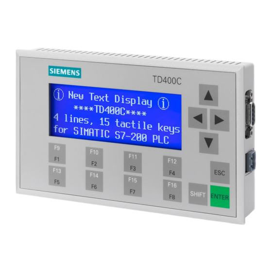
Introducing the S7-200 Text Display (TD) Devices Your S7-200 TD device is a 2- or 4-line text display device that can be connected to the S7-200 CPU. The TD device allows you to view, monitor, and change the process variables pertaining to your application. - Page 14 Figure 1-1 Text Display (TD) Devices The TD devices receive power from the S7-200 CPU through the TD/CPU cable. The TD 200, TD 200C and TD400C devices can also receive power from a separate power supply.
- Page 15 Each TD device functions as a network master when it is connected over a network that contains one or more S7-200 CPUs. The TD device is also designed to operate with other masters in a network. Multiple TD devices can be used with one or more S7-200 CPUs connected to the same network.
-
Page 16: Features Of The Text Display (Td) Devices
The TD device allows you to define a variable as a word, double word, or real ● Forcing or unforcing I/O points: You can force individual I/O points in the S7-200 CPU to be on or off (TD 200C, TD 200, and TD400C only) ●... - Page 17 Product Overview 1.3 Features of the Text Display (TD) Devices ● Latin 2 (with Boldface) ● Turkish (Latin 5) The TD devices provide system menus and prompts in six languages: English, German, French, Spanish, Italian, and Simplified Chinese. In the TD 100C, all fonts except Simplified Chinese are available in two sizes: 12 and 16 characters per row.
-
Page 18: Comparing The Td Devices
Alarms (from the Up to 40 alarm Up to 80 alarm Up to 80 alarm Up to 80 alarm S7-200 CPU) messages messages messages messages Alarm indicator (icon) Variable embedded in 1 per line... -
Page 19: Using The Td Device To Access Screens And Alarms
Product Overview 1.5 Using the TD Device to Access Screens and Alarms Feature TD 100C V 1.0 TD 200 V3.0 TD 200C V 1.0 TD400C V 2.0 System menu options Release the password Force I/O Force I/O Force I/O Set the time and date Release the password Release the password Release the password... - Page 20 ● Screens: You can create screens that allow the operator (using the TD device) to initiate the interaction with the S7-200 CPU. With the TD device, you can configure a user menu (up to 8 entries or groups for the TD 200C, TD 200, and TD400C, and up to 4 entries or groups for the TD 100C) that provides a hierarchy for the screens.
- Page 21 The TD device continuously polls the alarm bits to determine which alarms have been enabled. To display an alarm on the TD device, your user program in the S7-200 CPU must first set the alarm bit for the specific alarm. When your user program sets one of the alarm bits, the TD device then reads the alarm bits in the parameter block in the S7-200 CPU and displays the corresponding alarm message.
-
Page 22: Installation And Configuration Tasks
Product Overview 1.6 Installation and Configuration Tasks Figure 1-3 Screens and Alarms Installation and Configuration Tasks Installation and Configuration Tasks As shown in Figure 1-4, you use the Text Display wizard of STEP 7-Micro/WIN to configure the TD device. You can create a custom faceplate for the TD 100C, TD 200C, and TD400C. The Keypad Designer creates a keypad configuration file for the Text Display wizard. - Page 23 Product Overview 1.6 Installation and Configuration Tasks Figure 1-4 Configuration Tasks for the TD Devices Text Display (TD) User Manual System Manual, 08/2008, A5E00765548-03...
- Page 24 Product Overview 1.6 Installation and Configuration Tasks Figure 1-5 Installing Your TD 200 and TD 200C Device Text Display (TD) User Manual System Manual, 08/2008, A5E00765548-03...
- Page 25 Product Overview 1.6 Installation and Configuration Tasks Figure 1-6 Installing Your TD400C Device Text Display (TD) User Manual System Manual, 08/2008, A5E00765548-03...
- Page 26 Product Overview 1.6 Installation and Configuration Tasks Figure 1-7 Installing Your TD 100C Device Text Display (TD) User Manual System Manual, 08/2008, A5E00765548-03...
-
Page 27: Creating A Custom Faceplate For The Td Device
TD 100C, TD 200C, and the TD400C ● Word-processing application (optional): Prints multiple copies of the faceplate Siemens provides document files (in 6 languages) for Microsoft Word that help you to align the panel images for the perforations on the A4 blank faceplate material. To open... -
Page 28: Printing The Custom Faceplate For The Td Device
Product Overview 1.8 Printing the Custom Faceplate for the TD device Printing the Custom Faceplate for the TD device Printing the Custom Faceplate for the TD Device The TD 100C and the TD 200C ship with one blank faceplate (envelope-size) for printing the faceplate. - Page 29 Product Overview 1.8 Printing the Custom Faceplate for the TD device Contact your local Siemens representative or distributor to purchase additional quantities of the faceplate material. The order numbers are shown below: ● TD 200C: the order number for additional blank faceplates is 6ES7 272-1AF00-7AA0 ●...
- Page 30 Product Overview 1.8 Printing the Custom Faceplate for the TD device Text Display (TD) User Manual System Manual, 08/2008, A5E00765548-03...
-
Page 31: Installing Your Text Display (Td) Device
You can use the TD 200, version 3.0 and the TD 200C, version 1.0 with an existing TD 200 configuration without having to modify the control program in the S7-200 CPU. The TD 100C and the TD400C are not compatible with the TD 200 devices, nor with each other. - Page 32 ● The gasket must be replaced whenever the TD device is removed and reinstalled. To procure new gaskets, contact your Siemens distributor or sales representative. The TD 100C, TD 200, TD 200C, and TD400C devices are suitable for use in Class I, Division 2, Groups A, B, C, D;...
-
Page 33: Mounting The Td 200, Td 200C, And Td400C In A Panel Or On A Surface
Installing your Text Display (TD) Device 2.3 Mounting the TD 200, TD 200C, and TD400C in a Panel or on a Surface Mounting the TD 200, TD 200C, and TD400C in a Panel or on a Surface Mounting the TD 200, TD 200C, and TD400C in a Panel or on a Surface If you are using a customized label insert for your TD device, you must first install the new label insert before you mount the TD device. - Page 34 Installing your Text Display (TD) Device 2.3 Mounting the TD 200, TD 200C, and TD400C in a Panel or on a Surface Preparing the TD 200, TD 200C, and TD400C for Mounting Refer to the figure below and use the following procedure to separate the front cover from the housing of your TD device: 1.
-
Page 35: Mounting The Td 100C In A Panel Or On A Surface
Installing your Text Display (TD) Device 2.4 Mounting the TD 100C in a Panel or on a Surface Mounting the TD 200, TD 200C, and the TD400C Refer to Figure 2-3 and use the following procedure to complete the mounting of your TD device: 1. -
Page 36: Customizing The Labels For The Keys Of The Td 200
Installing your Text Display (TD) Device 2.5 Customizing the Labels for the Keys of the TD 200 Mounting the TD 100C Use the following procedure to complete the mounting of your TD 100. See figure below. 1. Remove the gasket from the protective cushion. 2. - Page 37 Installing your Text Display (TD) Device 2.5 Customizing the Labels for the Keys of the TD 200 5. Reinstall the front cover into the back housing. 6. Replace and tighten the three screws on the back of the TD device to ensure that the cover and housing are secure.
-
Page 38: Installing A Faceplate For The Td 100C, Td 200C And Td400C
Installing your Text Display (TD) Device 2.6 Installing a Faceplate for the TD 100C, TD 200C and TD400C Installing a Faceplate for the TD 100C, TD 200C and TD400C Installing a Faceplate for the TD 100C, TD 200C, and TD400C The TD 100C and TD 200C ship with a blank faceplate (envelope size) for creating a custom-designed faceplate. - Page 39 Installing your Text Display (TD) Device 2.6 Installing a Faceplate for the TD 100C, TD 200C and TD400C 4. Carefully lift back the unadhered faceplate and remove the rest of the protective paper from the TD device. 5. Carefully position the faceplate onto the TD device. Firmly press the faceplate onto the adhesive, taking care to remove any air bubbles that may have been trapped underneath.
- Page 40 Installing your Text Display (TD) Device 2.6 Installing a Faceplate for the TD 100C, TD 200C and TD400C Figure 2-8 Installing a Custom Faceplate on a TD Device Text Display (TD) User Manual System Manual, 08/2008, A5E00765548-03...
-
Page 41: Connecting The Td/Cpu Cable
TD device, see Chapter 5. If you require a longer cable (>2.5 m) to connect the TD device to the S7-200 CPU, use PROFIBUS components for the network connection. Refer to the SINEC IK10 Catalog. -
Page 42: Supplying Power For The Td Device
Supplying Power for the TD Device The S7-200 CPU uses the TD/CPU cable to provide power to the TD device. Use this type of power supply when the distance between the TD device and the S7-200 CPU is less than 2.5 m (the length of the TD/CPU cable). -
Page 43: Establishing A Connection For Your Td Device
The TD devices ship with a default configuration and are set to communicate at a rate of 9600 baud. The TD devices must communicate with the S7-200 CPU to be able to read the parameter block. You must configure your TD device to communicate at the same baud rate as your S7-200 CPU. - Page 44 Installing your Text Display (TD) Device 2.9 Establishing a Connection for Your TD Device Figure 2-10 Standard TD Keypad for the TD 100C, TD 200C and TD400C On an initial setup for the TD 100C, TD 200C, or TD400C, use the default keypad template shipped with the device to configure baud rates and addresses.
-
Page 45: Using The Keypad Designer To Create A Custom Faceplate For Your Text Display (Td) Device
TD400C with the Text Display wizard of STEP 7-Micro/WIN. Refer to Chapter 4 for information about the Text Display wizard. For more information about creating a custom faceplate, refer to FAQ 23707064 on the Siemens Internet site at www.siemens.com/S7-200. Using the Keypad Designer with Other Applications Using the Keypad Designer with Other Applications Use the Keypad Designer to create the custom-designed layout for the keypad. - Page 46 ● Word-processing application (optional): Prints multiple copies of the faceplate Siemens provides document files (in up to 6 languages depending upon your TD device) for Microsoft Word that helps you to align the panel images for the perforations on the A4 blank faceplate material.
- Page 47 Using the Keypad Designer to Create a Custom Faceplate for your Text Display (TD) Device 3.2 Using the Keypad Designer with Other Applications ● After you import the panel image into the Keypad Designer, you print the faceplate for the TD device.
-
Page 48: Starting The Keypad Designer
Using the Keypad Designer to Create a Custom Faceplate for your Text Display (TD) Device 3.3 Starting the Keypad Designer Starting the Keypad Designer Starting the Keypad Designer You use the Keypad Designer application to create a custom-designed layout for the keypad of the TD 100C, the TD 200C, or the TD400C. - Page 49 Using the Keypad Designer to Create a Custom Faceplate for your Text Display (TD) Device 3.3 Starting the Keypad Designer Figure 3-4 TD400C Keypad Template If you open a file with different target (for example, you are working on a TD 200C file, and you open a TD 100C file), the panel workspace resizes for the new target.
-
Page 50: Adding Buttons To The Keypad
Using the Keypad Designer to Create a Custom Faceplate for your Text Display (TD) Device 3.4 Adding Buttons to the Keypad Table 3- 1 Files Used by the Keypad Designer File Type Extension Description TD file *.td2 (TD 200C) Create the Keypad project file that stores the Open, Save, configuration data for the custom-designed keypad *.td1 (TD 100C) - Page 51 Using the Keypad Designer to Create a Custom Faceplate for your Text Display (TD) Device 3.4 Adding Buttons to the Keypad Inserting a Button With the TD 100C and the TD 200C, you can add a button to the keypad grid. The TD400C does not have this option.
-
Page 52: Defining The Properties Of The Button
Using the Keypad Designer to Create a Custom Faceplate for your Text Display (TD) Device 3.5 Defining the Properties of the Button Figure 3-8 Extending the Shape of a Button (TD 100C and TD 200C) Erasing an Area of the Button With the TD 100C and the TD 200C, you can change the shape of the button by clicking the Erase Button icon. - Page 53 Table 3-2 describes the functions that you can configure for the button. The default function is to set a bit in the S7-200 CPU (Set PLC Bit). Some functions can also be used in combination with other buttons, such as SHIFT or the arrow buttons.
- Page 54 Moves the cursor to the right Entering data Set Bit Sets a memory bit in the S7-200 CPU. You use the Text Display wizard to assign the specific bit address For the TD 200C and TD400C, you can use this button to set two different...
-
Page 55: Exporting The Keypad Layout To A Graphics Application
Using the Keypad Designer to Create a Custom Faceplate for your Text Display (TD) Device 3.6 Exporting the Keypad Layout to a Graphics Application Category Function Description View Messages Displays the View Messages screen (TD 200C, TD400C) Password Release Password Allows you to immediately restore the password-protection for the TD See Chapter 5 device No Function... -
Page 56: Adding A Panel Image To The Faceplate
Using the Keypad Designer to Create a Custom Faceplate for your Text Display (TD) Device 3.7 Adding a Panel Image to the Faceplate When you design the colors for your panel image, be aware that any white area will be printed as transparent (clear). - Page 57 Using the Keypad Designer to Create a Custom Faceplate for your Text Display (TD) Device 3.7 Adding a Panel Image to the Faceplate Figure 3-14 Creating the Panel Image: Import Panel Image Importing a Panel Image When you have completed the graphical design of panel image for the faceplate, you import the panel image back into the Keypad Designer.
-
Page 58: Saving The Keypad To A Td Configuration File
Using the Keypad Designer to Create a Custom Faceplate for your Text Display (TD) Device 3.8 Saving the Keypad to a TD Configuration File When you design your faceplate, you can create the bitmap with any resolution. However, the size of the background image for the TD device must exactly match the following dimensions: ●... -
Page 59: Reversing The Panel Image
Using the Keypad Designer to Create a Custom Faceplate for your Text Display (TD) Device 3.9 Reversing the Panel Image Figure 3-16 Saving the TD Configuration File The Keypad Designer allows you to save invalid or incomplete configurations. This allows you to save interim versions of your work. -
Page 60: Printing The Panel Image On A Faceplate
Using the Keypad Designer to Create a Custom Faceplate for your Text Display (TD) Device 3.10 Printing the Panel Image on a Faceplate Figure 3-17 Reversed Panel Image Figure 3-18 Non-reversed Panel Image 3.10 Printing the Panel Image on a Faceplate Printing the Panel Image on a Faceplate To print your custom-designed panel image onto the blank faceplate material, you must use a laser printer that supports printing transparency material in both the A4 and envelope... - Page 61 TD200C, and TD400C): You can use the Microsoft Word template to print the faceplate onto perforated areas of the material. You do not have to cut the faceplates from the material. Order these A4 sheets from your Siemens distributor. See Appendix A for order numbers.
- Page 62 Siemens provides document files (in 6 languages) for Microsoft Word that helps you to align the panel images for the perforations on the A4 blank faceplate material. To open these...
- Page 63 Using the Keypad Designer to Create a Custom Faceplate for your Text Display (TD) Device 3.10 Printing the Panel Image on a Faceplate Figure 3-21 Printing Multiple Faceplates To export the panel image to your word-processing application: 1. Open your word-processing application (Microsoft Word) and open the template file. 2.
-
Page 64: Installing The Printed Faceplate Onto The Td Device
Using the Keypad Designer to Create a Custom Faceplate for your Text Display (TD) Device 3.11 Installing the Printed Faceplate onto the TD device 3.11 Installing the Printed Faceplate onto the TD device Installing the Printed Faceplate onto the TD 100C, TD 200C, and TD400C Use the following procedure to install your custom faceplate on the TD device. - Page 65 Using the Keypad Designer to Create a Custom Faceplate for your Text Display (TD) Device 3.11 Installing the Printed Faceplate onto the TD device Figure 3-22 Adhering the Faceplate onto the TD Device Text Display (TD) User Manual System Manual, 08/2008, A5E00765548-03...
- Page 66 Using the Keypad Designer to Create a Custom Faceplate for your Text Display (TD) Device 3.11 Installing the Printed Faceplate onto the TD device Text Display (TD) User Manual System Manual, 08/2008, A5E00765548-03...
-
Page 67: Using The Text Display Wizard To Configure The S7-200 Cpu For Your Text Display (Td) Device
Overview of the Configuration Tasks Overview of the Configuration Tasks The S7-200 CPU stores the configuration data for the TD device, including the screens and alarms, into a parameter block (located in V memory). The Text Display wizard creates the parameter block. - Page 68 Using the Text Display Wizard to Configure the S7-200 CPU for Your Text Display (TD) Device 4.2 Overview of the Configuration Tasks Figure 4-1 Using the Text Display Wizard to Configure the TD Device Text Display (TD) User Manual System Manual, 08/2008, A5E00765548-03...
- Page 69 Using the Text Display Wizard to Configure the S7-200 CPU for Your Text Display (TD) Device 4.2 Overview of the Configuration Tasks Figure 4-2 Configuration Tasks of the Text Display Wizard Text Display (TD) User Manual System Manual, 08/2008, A5E00765548-03...
-
Page 70: Configuring The Text Display Device
Using the Text Display Wizard to Configure the S7-200 CPU for Your Text Display (TD) Device 4.3 Configuring the Text Display Device Configuring the Text Display Device Configuring the Text Display (TD) Device STEP 7-Micro/WIN provides a wizard that makes it easy to configure the parameter block and the messages in the data memory area of the S7-200 CPU. - Page 71 Using the Text Display Wizard to Configure the S7-200 CPU for Your Text Display (TD) Device 4.3 Configuring the Text Display Device Starting the Text Display Wizard for the TD Device You use the Text Display wizard to configure the parameters for the TD device. You can also use the Text Display wizard to modify an existing TD configuration.
- Page 72 Using the Text Display Wizard to Configure the S7-200 CPU for Your Text Display (TD) Device 4.3 Configuring the Text Display Device Figure 4-5 Selecting the TD Device Selecting a Password for the TD Device Selecting a password for the TD device helps you to protect the security of your process or application.
- Page 73 ● Setting the Time-of-Day clock: Allows you to set the time and date for the S7-200 CPU ● Forcing I/O: Allows you to force I/O points in the S7-200 CPU to be on or off Figure 4-6...
- Page 74 Using the Text Display Wizard to Configure the S7-200 CPU for Your Text Display (TD) Device 4.3 Configuring the Text Display Device ● Changing the operating mode: Allows you to set the S7-200 CPU to STOP or RUN ● Editing the CPU memory: Allows you to view and change the values of the data stored in...
- Page 75 Selecting the Update Rate for the TD Device You can select how often the TD device performs a read operation to update the information from the S7-200 CPU. You can select from "As fast as possible" to "Every 15 seconds" (in one-second increments).
- Page 76 Using the Text Display Wizard to Configure the S7-200 CPU for Your Text Display (TD) Device 4.3 Configuring the Text Display Device When you create multiple language sets (TD 200, TD 200C, and TD400C), the Text Display wizard copies the alarms and screens from the primary language set to the other language set.
- Page 77 Using the Text Display Wizard to Configure the S7-200 CPU for Your Text Display (TD) Device 4.3 Configuring the Text Display Device Loading a Custom Keypad (TD 100C, TD 200C, and TD400C Only) The TD 100C, TD 200C, and TD400C allow you to create a custom keypad. As described in Chapter 3, you can insert buttons onto the keypad.
- Page 78 ● The TD400C can be configured for up to 15 configurable buttons The Configure Keypad Buttons dialog of the Text Display wizard displays only those buttons that set bits in the S7-200 CPU. The Text Display wizard does not list the buttons with other functionality, such as ESC or SHIFT.
-
Page 79: Configuring The Screens For The Text Display Device
Using the Text Display Wizard to Configure the S7-200 CPU for Your Text Display (TD) Device 4.4 Configuring the Screens for the Text Display Device The TD device only sets the bit on or off in the S7-200 CPU a single time when the TD device button is either pressed or released. - Page 80 Using the Text Display Wizard to Configure the S7-200 CPU for Your Text Display (TD) Device 4.4 Configuring the Screens for the Text Display Device Figure 4-14 Navigating through a Hierarchy of User-Defined Screens The screens in the TD 200 and TD 200C are always two lines. The screens in the TD 100C are always four lines.
- Page 81 Using the Text Display Wizard to Configure the S7-200 CPU for Your Text Display (TD) Device 4.4 Configuring the Screens for the Text Display Device ● Add icons to the text message (TD 200C and TD400C only) ● Determine the sequence of the screens for each group...
- Page 82 Using the Text Display Wizard to Configure the S7-200 CPU for Your Text Display (TD) Device 4.4 Configuring the Screens for the Text Display Device Figure 4-16 Defining the User Menu Creating the Text for a Screen Your screen message can contain the following elements: ●...
- Page 83 Using the Text Display Wizard to Configure the S7-200 CPU for Your Text Display (TD) Device 4.4 Configuring the Screens for the Text Display Device Figure 4-17 Creating the Message for a TD 200C Screen Figure 4-18 Creating the Message for a TD400C Screen Embedding a Variable into the Text of a Screen You can embed a variable data field into the text of the screen.
- Page 84 Using the Text Display Wizard to Configure the S7-200 CPU for Your Text Display (TD) Device 4.4 Configuring the Screens for the Text Display Device For the TD 200, TD 200C, and the TD400C, you can embed up to 6 variables per screen.
- Page 85 Using the Text Display Wizard to Configure the S7-200 CPU for Your Text Display (TD) Device 4.4 Configuring the Screens for the Text Display Device The actual number of characters used to display a value varies with the size of the value. To help calculate the number of characters required for displaying the value of the variable, see the examples listed in Table 4-1.
- Page 86 Using the Text Display Wizard to Configure the S7-200 CPU for Your Text Display (TD) Device 4.4 Configuring the Screens for the Text Display Device When you embed a string variable in a TD alarm or screen, the Text Display wizard shows the embedded variable occupying 4 character spaces (or 2 Chinese characters) for the variable.
-
Page 87: Configuring The Alarms
Using the Text Display Wizard to Configure the S7-200 CPU for Your Text Display (TD) Device 4.5 Configuring the Alarms Figure 4-22 Using STR_CPY to Create Strings Configuring the Alarms Configuring the Alarms Alarms allow the user program in the S7-200 CPU to initiate interaction with the operator by displaying an alarm message on the TD device. - Page 88 Using the Text Display Wizard to Configure the S7-200 CPU for Your Text Display (TD) Device 4.5 Configuring the Alarms ● Priority for the alarms is determined by the sequence in which you configure the alarms: – The first alarm has the highest priority –...
- Page 89 Pressing ENTER for the last editable variable of an alarm writes this last value to the S7-200 CPU and the TD device then resets the alarm enable bit. For more information on editing variables, see Editing a Variable that is Embedded in an Alarm or a Screen in Chapter 5.
- Page 90 Another alarm cannot replace the one flashing until the operator acknowledges the flashing alarm. This is also true even if a higher priority alarm is enabled in the S7-200 CPU. If the TD device is configured for single line alarms and the CPU enables a higher priority alarm, the flashing alarm shifts down to the next line of the display.
- Page 91 Using the Text Display Wizard to Configure the S7-200 CPU for Your Text Display (TD) Device 4.5 Configuring the Alarms Figure 4-25 Configuring the TD 200C Alarm Options Figure 4-26 Configuring the TD400C Alarm Options The TD 200, TD 200C, and the TD400C support up to 80 alarms, and the TD 100C supports up to 40 alarms.
- Page 92 Using the Text Display Wizard to Configure the S7-200 CPU for Your Text Display (TD) Device 4.5 Configuring the Alarms ● Variable data (optional): Click the Insert PLC Data button to embed a variable into the text message ● Fonts: For the TD400C you select the font to use for the alarm message To ensure that important alarms are acknowledged by an operator, you can configure the alarm to require acknowledgement.
- Page 93 Using the Text Display Wizard to Configure the S7-200 CPU for Your Text Display (TD) Device 4.5 Configuring the Alarms Embedding a Variable into the Text of an Alarm You can embed a variable data field into the text of the alarm. To embed a variable, move the cursor to the location for the variable in your text and click the Insert PLC Data button.
- Page 94 Using the Text Display Wizard to Configure the S7-200 CPU for Your Text Display (TD) Device 4.5 Configuring the Alarms Data values are always right-justified to the right-most character of an embedded variable. As a data value grows in magnitude, it utilizes more spaces to the left of the anchor point and can overwrite the text characters.
-
Page 95: Configuring The Language Sets (Td 200, Td 200C, And Td400C)
Using the Text Display Wizard to Configure the S7-200 CPU for Your Text Display (TD) Device 4.6 Configuring the Language Sets (TD 200, TD 200C, and TD400C) Configuring the Language Sets (TD 200, TD 200C, and TD400C) Configuring the Language Sets for the TD Device (TD 200, TD 200C, TD400C) - Page 96 Using the Text Display Wizard to Configure the S7-200 CPU for Your Text Display (TD) Device 4.6 Configuring the Language Sets (TD 200, TD 200C, and TD400C) 4. (Optional) Select the option for primary language to configure the new language as the default language set for the TD device.
- Page 97 Using the Text Display Wizard to Configure the S7-200 CPU for Your Text Display (TD) Device 4.6 Configuring the Language Sets (TD 200, TD 200C, and TD400C) Figure 4-31 Localizing the Display Notes for Using the Simplified Chinese Character Set The Simplified Chinese character set requires a Chinese version of Windows or a Chinese emulator to properly display Chinese characters in the Text Display wizard.
-
Page 98: Assigning The V Memory Address For The Parameter Block
Using the Text Display Wizard to Configure the S7-200 CPU for Your Text Display (TD) Device 4.7 Assigning the V Memory Address for the Parameter Block You cannot fit one single-byte character plus one double-byte character in a character position. - Page 99 Using the Text Display Wizard to Configure the S7-200 CPU for Your Text Display (TD) Device 4.8 Finishing the Configuration for the TD Device ● TD_ALM_x (where x is the TD configuration number) – Your user program uses this subroutine to call the alarm by the symbolic name (configured by the Text Display wizard).
- Page 100 Using the Text Display Wizard to Configure the S7-200 CPU for Your Text Display (TD) Device 4.8 Finishing the Configuration for the TD Device Text Display (TD) User Manual System Manual, 08/2008, A5E00765548-03...
-
Page 101: Operating Your Text Display (Td) Device
Included in this chapter is information about routine operator tasks, such as entering and releasing the password, editing variables embedded in a message or screen, and checking the status information of the S7-200 CPU. This chapter also describes the less-routine diagnostic functions provided by the TD device for troubleshooting problems in the S7-200... - Page 102 Operating Your Text Display (TD) Device 5.2 Using the Text Display Device to Access Screens and Alarms As shown in Figure 5-1 and Figure 5-2, the standard TD keypad provides the following buttons: ● ENTER and Escape (ESC) buttons: – ENTER selects a menu item or confirms a value. –...
- Page 103 The backlight will turn on when: ● The TD400C is powered on ● The S7-200 CPU forces a reset of the TD400C with the TD_Reset bit in the TD parameter block. ● You press a key. The time is extended each time a key is pressed.
- Page 104 The textual message of the screen or alarm can convey information for the operator and can also allow the operator to interact with the S7-200 CPU by changing the embedded value of a variable (such as a set point or limit).
- Page 105 Operating Your Text Display (TD) Device 5.2 Using the Text Display Device to Access Screens and Alarms Figure 5-2 Using the Keypad to Navigate between User Menus and Screens Figure 5-3 Displaying and Acknowledging Alarms Text Display (TD) User Manual System Manual, 08/2008, A5E00765548-03...
-
Page 106: Accessing The Menus And Screens
SHIFT+UP to move left and SHIFT+DOWN to move right. ● Updating the data in the S7-200 CPU: Pressing ENTER writes the updated value for the variable to the S7-200 CPU and moves the cursor to the next editable variable on the screen. - Page 107 Operating Your Text Display (TD) Device 5.3 Accessing the Menus and Screens Figure 5-4 Menu Hierarchy for the TD 200, TD 200C, and TD400C Text Display (TD) User Manual System Manual, 08/2008, A5E00765548-03...
- Page 108 Operating Your Text Display (TD) Device 5.3 Accessing the Menus and Screens Figure 5-5 Menu Hierarchy for the TD 100C Text Display (TD) User Manual System Manual, 08/2008, A5E00765548-03...
-
Page 109: Entering And Releasing A Password
CPU password as soon as the operator exits the function that required the password. For example: If the operator entered the CPU password in order to force an I/O point in the S7-200 CPU, the TD device releases the CPU password as soon as the operator exits the Force menu. -
Page 110: Viewing The Screens And The Alarms
Operating Your Text Display (TD) Device 5.5 Viewing the Screens and the Alarms Figure 5-6 Release Password Command Viewing the Screens and the Alarms Viewing the Screens and the Alarms As described in Chapter 4, you can configure screens and alarms for the TD device. If you configure both alarms and screens, you also designate which set of messages (screens or alarms) are the default display mode for the TD device. - Page 111 Operating Your Text Display (TD) Device 5.5 Viewing the Screens and the Alarms Figure 5-7 TD 200, TD 200C, and TD400C - Navigating between the Default and Secondary Displays Text Display (TD) User Manual System Manual, 08/2008, A5E00765548-03...
- Page 112 Operating Your Text Display (TD) Device 5.5 Viewing the Screens and the Alarms Figure 5-8 TD 100C - Navigating between the Default and Secondary Displays Displaying the Alarms If you created both screens and alarms when you configured the TD device, the main menu of the TD device includes a command that allows you to access the secondary (non-default) display.
- Page 113 After reading a new alarm from the S7-200 CPU, the TD device sorts the alarms again to display the highest priority alarms at the top of the list. The TD device determines the priority based on the sequence of the alarms in the parameter block: ●...
- Page 114 Another alarm cannot replace the one flashing until the operator acknowledges the flashing alarm. This is also true even if a higher priority alarm is enabled in the S7-200 CPU. If the TD device is configured for single line alarms and the CPU enables a higher priority alarm, the flashing alarm shifts down to the next line of the display.
- Page 115 When the alarm is enabled in the S7-200 CPU, the TD device notes this and, if there is space available on the display, reads the alarm from the CPU. The TD device then displays the alarm and causes the entire alarm to flash to notify the operator that the alarm is present and must be acknowledged.
- Page 116 Operating Your Text Display (TD) Device 5.5 Viewing the Screens and the Alarms Notice Due to restrictions in the format used to store real (floating-point) numbers in both the S7- 200 CPU and the TD device, the accuracy of the number is limited to six significant digits. Editing a real number with more than six digits may not change the value of the variable, or may cause other digits within the number to change: ●...
- Page 117 Operating Your Text Display (TD) Device 5.5 Viewing the Screens and the Alarms TD Bit Usage A summary of the TD bit usage is shown in Table 5-1. Table 5- 1 Summary of TD Bit Usage Bits Associated Enable Condition Results shown on the TD Display Clear Condition for the Bit with Alarms and...
- Page 118 Operating Your Text Display (TD) Device 5.5 Viewing the Screens and the Alarms Bits Associated Enable Condition Results shown on the TD Display Clear Condition for the Bit with Alarms and for the Bit Screens ALARM Alarm The user acknowledges an alarm message by The TD device will set the ACKNOW- acknowledgement...
-
Page 119: Performing Typical Or Routine Operator Tasks
Performing Typical or Routine Operator Tasks The Operator Menu allows you to perform the following tasks: ● Determining the model and version of the S7-200 CPU (CPU Status) ● Viewing the error messages generated by the S7-200 CPU (CPU Status) - Page 120 Press the UP or DOWN arrows to display the error messages that were generated by the S7-200 CPU. The TD device displays an error message only if an error exists in the S7-200 CPU. The CPU classifies errors as either fatal errors or non-fatal errors.
- Page 121 Setting Time and Date in the S7-200 CPU You can use the TD device to change the time-of-day settings in the S7-200 CPU. This allows an operator to easily adjust for time changes. The TD device does not maintain time and date settings. In order to display the time and date values, the TD device reads the current time and date from the S7-200 CPU and displays these values.
- Page 122 5.6 Performing Typical or Routine Operator Tasks If the TD device was not configured to allow changes to the time or if the S7-200 CPU does not support the TOD clock, the Set Time and Date command does not appear on the Operator Menu.
- Page 123 Operating Your Text Display (TD) Device 5.6 Performing Typical or Routine Operator Tasks Changing the Language Set (TD 200C, TD 200, and TD400C only) You can use the TD device to change the language set in order to localize the TD device for another country.
-
Page 124: Performing Specialized Operator Tasks (Diagnostic/Setup Menu)
Performing Specialized Operator Tasks (Diagnostic/Setup Menu) Some of the pre-configured tasks provided by the TD device provide assistance with setting up the TD device or troubleshooting problems with the S7-200 CPU. These functions are typically accessed infrequently. See the figures below. - Page 125 TD device, such as network addresses, address of the parameter block (stored in V memory of the S7-200 CPU), baud rate, and other communication parameters. ● Setting the network address for the TD device: Use the UP or DOWN arrow to set the network address (default address = 1).
- Page 126 Use the UP or DOWN arrow to select the baud rate. The baud rate must match the baud rate of the S7-200 CPU and any other device on the same network. ● Setting the Highest Station: Changes the highest station address for the TD device. This setting tells the TD device which network addresses to check when looking for other network master devices.
- Page 127 Viewing the TD Messages Stored in the S7-200 CPU (TD 200, TD 200C, and TD400C only) You can review all of the TD messages (screens and alarms) that you configured for the TD device within the language set currently selected for the TD device.
- Page 128 Text Display wizard. See Chapter 4. You can use the TD device to change the operating mode of the S7-200 CPU from STOP to RUN or from RUN to STOP. The operator may need to enter the TD password, if the TD device is configured for password-protection.
- Page 129 Display wizard. See Chapter 4. You can use the TD 200C and TD400C to copy the user program in the S7-200 CPU to a memory cartridge (MC). The operator may need to enter both the TD password and the CPU password, if both the TD device and the S7-200 CPU are configured for password- protection.
- Page 130 ● To edit the value stored in the memory address: Use the UP or DOWN arrows to change the value. Press ENTER to write the new values to the memory address in the S7-200 CPU. Pressing ESC aborts the function.
- Page 131 5.7 Performing Specialized Operator Tasks (Diagnostic/Setup Menu) Table 5-3 lists the memory address and data types possible. For information about the memory areas, sizes of the data, and data types supported by your S7-200 CPU, refer to the S7-200 Programmable Controller System Manual.
- Page 132 (For example: The TD device displays 0.00000005 as 0.0000001, and displays real numbers less than 0.00000005 as "0.0".) The TD device writes the number displayed to the S7-200 CPU without rounding. HEX Hexadecimal (valid for Byte, Word, and Double-word) BIN Binary (valid for Byte and Word only) Binary values are displayed in the same pattern (7..0) as discussed in the...
-
Page 133: Technical Specifications And Reference Information
Technical Specifications and Reference Information General Specifications for the Text Display Devices General Technical Specifications for the Text Display Devices Order Number Description Dimensions (mm) (H x H x D) Weight 6ES7 272- 1BA10-0YA1 TD 100C Operator Interface 89.6 x 76 x 35.7 0.11 kg 6ES7 272-0AA30-0YA1 TD 200 Operator Interface... - Page 134 0.2 Nm (about 0.5 mm the height of the seal). The gasket must be replaced whenever the TD device is removed and reinstalled. To procure new gaskets, contact your Siemens distributor or sales representative. To ensure compliance of the TD 200C and TD 200 with IP 65 and UL 50 Type 4X, you must follow these guidelines. The minimum panel thickness must be at least 1.5 mm.
- Page 135 Technical Specifications and Reference Information A.2 Technical Specifications for the TD 100C, TD 200 and TD 200C General TD 100C TD 200 TD 200C 6ES7 272-1BA10-0YA1 6ES7 272-0AA30-0YA1 6ES7 272-1AA10-0YA1 Conducted interference on Not applicable ±2kV according to IEC 61000-4-4; Burst DC power supply line ±1kV according to IEC 61000-4-5;...
-
Page 136: Technical Specifications For The Td400C
24 VDC, 15 VDC ... 30 VDC, safety extra low voltage, NEC Class 2 or limited power source (supplied by the S7-200 CPU, mains adapter or a 24 VDC external supply). The TD device has no integrated means of protection against strong interference pulses in the microsecond range (surge impulse). -
Page 137: Certificates, Directives And Declarations For The Td Device
Technical Specifications and Reference Information A.4 Certificates, Directives and Declarations for the TD Device General TD400C 6AV6640-0AA00-0AX1 Noise immunity to high 10 V with 80% amplitude modulation at 1 kHz, 10 kHz to 80 MHz frequency emission 10 V/m with 80% amplitude modulation at 1 kHz, 80 MHz to 1 GHz 3 V/m with 80% amplitude modulation at 1.4 GHz to 2 GHz 1 V/m with 80% amplitude modulation at 2.0 GHz to 2.7 GHz Climatic Conditions... - Page 138 Declaration of Conformity (TD 200C, TD 200, and TD400C) The EC declarations of conformity and the documentation relating to this are available to the authorities concerned, according to the above EC directive, from: Siemens AG Bereich Automatisierungs- und Antriebstechnik I IA AS RD ST...
-
Page 139: Approvals For Usa, Canada And Australia
Technical Specifications and Reference Information A.5 Approvals for USA, Canada and Australia Approvals for USA, Canada and Australia Approvals for USA, Canada and Australia The characters stamped on a device are indicative of the requirements which that device meets: Underwriters Laboratories: cULus Approval, Hazardous Location cULus Listed 21BP I.T.E. - Page 140 Technical Specifications and Reference Information A.5 Approvals for USA, Canada and Australia FM Approval Notes FM approval, if present, is to Factory Mutual Approval Standard Class Number 3611, Class I, Division 2, Group A, B, C, D, and Class I, Zone 2, Group IIC. Temperature class T5 is adhered to when the ambient temperature during operation does not exceed 50 degrees C.
-
Page 141: Standard Td Character Set (Td 200, Td 200C)
Technical Specifications and Reference Information A.6 Standard TD Character Set (TD 200, TD 200C) Standard TD Character Set (TD 200, TD 200C) Standard TD Character Set (TD 200, TD 200C) Figure A-1 Standard TD Character Set for the TD 200 and TD 200C Text Display (TD) User Manual System Manual, 08/2008, A5E00765548-03... - Page 142 Technical Specifications and Reference Information A.6 Standard TD Character Set (TD 200, TD 200C) Figure A-2 Standard TD Character Set for the TD 200 and TD 200C (continued) Alt Key Combinations for International and Special Characters Certain international and special characters may not display correctly on the TD display if entered with the Text Display wizard with the standard TD character set.
- Page 143 Technical Specifications and Reference Information A.6 Standard TD Character Set (TD 200, TD 200C) Character ALT + Key Combination Alt + 0252 (double bar) Alt + 0253 ( triple bars) [[[[ Alt + 0254 (four bars) [[[[[ Alt + 0255 (five bars) ↑...
-
Page 144: Arabic Character Set (Td 200, Td 200C, And Td400C)
Technical Specifications and Reference Information A.7 Arabic Character Set (TD 200, TD 200C, and TD400C) Arabic Character Set (TD 200, TD 200C, and TD400C) Arabic Character Set (TD 200, TD 200C, and TD400C) Figure A-4 Arabic Character Set Text Display (TD) User Manual System Manual, 08/2008, A5E00765548-03... -
Page 145: Baltic Character Set
Technical Specifications and Reference Information A.8 Baltic Character Set Baltic Character Set Baltic Character Set Figure A-5 Baltic Character Set Text Display (TD) User Manual System Manual, 08/2008, A5E00765548-03... -
Page 146: Simplified Chinese Character Set
Technical Specifications and Reference Information A.9 Simplified Chinese Character Set Simplified Chinese Character Set Simplified Chinese Character Set The TD devices support the Simplified Chinese character set (GB2312-80) for the People's Republic of China. The TD devices use Microsoft Windows encoding for this character set. The Windows encoding allows the TD devices to display the same characters as shown in the STEP 7-Micro/WIN Text Display wizard when you are using a Chinese emulator or a Chinese version of Microsoft Windows. - Page 147 Technical Specifications and Reference Information A.9 Simplified Chinese Character Set TD 100C does not support the entire Simplified Chinese character set, however, the most- used characters have been included in the TD 100C. See the Simplified Chinese Characters Set for a list of supported characters. Characters that are not supported by the TD 100C are displayed as a square.
-
Page 148: Cyrillic Character Set
Technical Specifications and Reference Information A.10 Cyrillic Character Set A.10 Cyrillic Character Set Cyrillic Character Set Figure A-7 Cyrillic Character Set Text Display (TD) User Manual System Manual, 08/2008, A5E00765548-03... -
Page 149: Greek Character Set
Technical Specifications and Reference Information A.11 Greek Character Set A.11 Greek Character Set Greek Character Set Figure A-8 Greek Character Set Text Display (TD) User Manual System Manual, 08/2008, A5E00765548-03... -
Page 150: Hebrew Character Set (Td 200, Td 200C, And Td400C)
Technical Specifications and Reference Information A.12 Hebrew Character Set (TD 200, TD 200C, and TD400C) A.12 Hebrew Character Set (TD 200, TD 200C, and TD400C) Hebrew Character Set (TD 200, TD 200C, and TD400C) Figure A-9 Hebrew Character Set Text Display (TD) User Manual System Manual, 08/2008, A5E00765548-03... -
Page 151: Latin 1 Character Set
Technical Specifications and Reference Information A.13 Latin 1 Character Set A.13 Latin 1 Character Set Latin 1 Character Set Figure A-10 Latin 1 Character Set Text Display (TD) User Manual System Manual, 08/2008, A5E00765548-03... -
Page 152: Latin 2 Character Set
Technical Specifications and Reference Information A.14 Latin 2 Character Set A.14 Latin 2 Character Set Latin 2 Character Set Figure A-11 Latin 2 Character Set Text Display (TD) User Manual System Manual, 08/2008, A5E00765548-03... -
Page 153: Turkish (Latin 5) Character Set
Technical Specifications and Reference Information A.15 Turkish (Latin 5) Character Set A.15 Turkish (Latin 5) Character Set Turkish (Latin 5) Character Set Figure A-12 Turkish (Latin 5) Character Set Text Display (TD) User Manual System Manual, 08/2008, A5E00765548-03... - Page 154 Technical Specifications and Reference Information A.15 Turkish (Latin 5) Character Set Text Display (TD) User Manual System Manual, 08/2008, A5E00765548-03...
-
Page 155: Connecting Multiple Devices On A Network
In this example: ● TD 200 Number 1 is configured to communicate to the S7-200 CPU at address 2 (CPU 1) ● TD 200 Number 2 is configured to communicate to the S7-200 CPU at address 3 (CPU 2) You can connect multiple TD devices to a single S7-200 CPU. -
Page 156: Determining The Distances, Transmission Rate, And Cable
Network connectors are available from Siemens. Using these connectors allows you to isolate the CPUs from one another (the 24 VDC), but still allows you to power the TD device from the CPU. See the SIMATIC S7-200 Programmable Controller System Manual for more information about using network connectors. -
Page 157: Selecting The Network Cable
Sample Network with Repeaters Selecting the Network Cable Selecting the Network Cable S7-200 networks use the RS-485 standard on twisted pair cables. Table B-2 lists the specifications for the network cable. You can connect up to 32 devices on a network segment. -
Page 158: Building A Td/Cpu Cable
Building a TD/CPU Cable Building a TD/CPU Cable The TD/CPU cable is used for connecting a display device to an S7-200 CPU. If you do not have a TD/CPU cable, refer to Figures B-4 and B-5 to create your own cable. - Page 159 B.6 Building a TD/CPU Cable Figure B-4 shows you the pin-out of TD/CPU cable with power supplied to the TD device. Use this option when you want the TD device to receive power from an S7-200 CPU. Figure B-4 TD/CPU Cable with Power Connections...
-
Page 160: Cpu Grounding And Circuit Reference Point Guidelines For Using Isolated Circuits
● When you connect CPUs with different ground potentials to the same PPI network, you should use an isolated RS-485 repeater. ● S7-200 products include isolation boundaries at certain points to help prevent unwanted current flows in your installation. When you plan your installation, you should consider where these isolation boundaries are provided, and where they are not provided. - Page 161 Connecting Multiple Devices on a Network B.7 CPU Grounding and Circuit Reference Point Guidelines for Using Isolated Circuits ● DC digital inputs and outputs are isolated from logic circuit to 500 VAC. ● DC digital I/O groups are isolated from each other by 500 VAC. ●...
- Page 162 Connecting Multiple Devices on a Network B.7 CPU Grounding and Circuit Reference Point Guidelines for Using Isolated Circuits Text Display (TD) User Manual System Manual, 08/2008, A5E00765548-03...
-
Page 163: Troubleshooting
Be sure all addresses are valid for the but it contains errors. S7-200 CPU. No CPU COMM Address of the S7-200 CPU is incorrect Correct the address error S7-200 CPU does not have power Power up the CPU Cable problems... - Page 164 Troubleshooting C.1 Troubleshooting Guide Problem Possible Cause Possible Solution Display backlight is on, but no message Program checksum failure Defective hardware: Replace with a is displayed new TD device User cannot access the TD system The custom keypad does not contain To restore the standard TD keypad: menus the ESC and ENTER buttons...
-
Page 165: Index
Index CE Labeling, 5 CE Symbol, 138 certification, 5 character set selecting, 75 agency approvals Character sets Canadian Standards Association (CSA), 4 Standard Character Set, 147 Underwriters Laboratories (UL), 4 Character Sets alarms, 110 Arabic, 144 accessing, 19 Cyrillic, 148 alarm parameters, 90 Greek, 149 configuring, 87... - Page 166 Index CPU address, 125 printing panel image to, 60 CPU Grounding, 160 procedure to install, 38 CPU memory faceplate for TD 100C and TD 200C, 32 editing, 129 faceplate, blank CPU memory address and data type, 131 ordering information, 28 CPU operating mode, 128 Factory Mutual (FM) approvals, 140 CPU Status, 120...
- Page 167 21 parameter block address, 125 password, 109 Password, selecting, 72 pnel image manuals adding to faceplate, 56 S7-200 Programmable Controller System Manual, 3 importing, 56 memory cartridge power connector, 15 copying to, 129 power, supplying, 42 menu hierarchy, 106...
- Page 168 Index Standard Character Set (ASCII), 147 Text Display wizard, 15 standard faceplate, 43 starting, 71 standard functions, 106 tasks for configuring, 70 Standard TD Character Set, 141 Time and Date, 121 STEP 7-Micro/WIN, 15 Troubleshooting the TD device, 163 versions, 3 Turkish (Latin 5) Character Set, 153 STOP/RUN mode, 128 summary of configuration, 98...