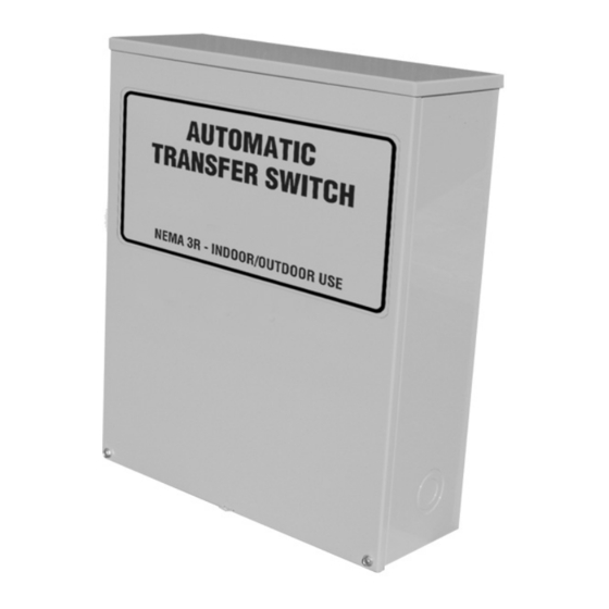
Summary of Contents for Generac Power Systems 004635-3, 004678-2
- Page 1 Automatic Transfer Switch Owner’s Manual ATS “HS” Type Models: 004635-3 (200 Amp, 250 Volts) and 004678-2 (100 Amp, 250 Volts) This manual should remain with the unit.
-
Page 2: General Hazards
SAVE THESE INSTRUCTIONS! Read the following information carefully before attempting to install, operate or service this equipment. Also read the instructions and information on tags, decals, and labels that may be affixed to the transfer switch. Replace any decal or label that is no longer legible. -
Page 3: Table Of Contents
• Never work on this equipment while physically or mentally fatigued. • Keep the transfer switch enclosure door closed and bolted at all times. Only qualified personnel should be permitted access to the switch interior. • In case of an accident caused by electric shock, immediately shut down the source of electrical power. -
Page 4: Safety Rules
The transfer switch is for use in optional standby sys- tems only. The transfer switch is suitable for use on a circuit capable of 10,000 rms symmetrical amperes, 240 VAC when protected by a circuit breaker without an adjustable short time response or by fuses. -
Page 5: Section 2 - Installation
Never install a transfer switch that has been dam- aged. Install the transfer switch as close as possible to the electrical loads that are to be connected to it. Mount the switch vertically to a rigid supporting structure. -
Page 6: Connecting Start Circuit Wires
Also read the information and instructions of labels and decals affixed to the switch. Note any options or accessories that might be installed and review their operation. A manual HANDLE is shipped with the transfer switch. -
Page 7: Close To Emergency Source Side
Attach handle to actuating shaft. ◆ 3.2.2 CLOSE TO EMERGENCY SOURCE SIDE Before proceeding, verify the position of the switch by observing the position of the manual operation han- dle in Figure 3.1. If the handle is DOWN, the contacts are closed in the EMERGENCY (STANDBY) position. -
Page 8: Generator Tests Under Load
6. Let the generator run at no-load for several minutes. Then, shut down by setting the AUTO- OFF-MANUAL switch to its OFF position. 7. Move the switch's main contacts back to their UTILITY position. For example, load connected to UTILITY power supply. -
Page 9: Section 4 - Notes
Section 4 — Notes ATS “HS” Type Transfer Switch... - Page 10 Section 4 — Notes ATS “HS” Type Transfer Switch...
- Page 11 Section 4 — Notes ATS “HS” Type Transfer Switch...
-
Page 12: Section 5 - Installation Diagram
Section 5 — Installation Diagram ATS “HS” Type Transfer Switch Drawing No. 0E7081... -
Page 13: Section 6 - Electrical Data
Section 6 — Electrical Data ATS “HS” Type Transfer Switch Transfer Switch Interconnections - Drawing No. 074106-B LOAD LOAD UTILITY UTILITY... - Page 14 Section 6 — Electrical Data ATS “HS” Type Transfer Switch Electrical Schematic - Drawing No. 0E6093-B...
- Page 15 Section 6 — Electrical Data ATS “HS” Type Transfer Switch Electrical Schematic - Drawing No. 0E6093-B...
-
Page 16: Section 7 - Exploded Views & Parts Lists
Section 7 — Exploded Views and Parts List ATS “HS” Type Transfer Switch 100A Transfer Switch Assembly – Drawing No. 0E8403$-F... - Page 17 **** NOT SHOWN ON THIS ASSEMBLY, CENTER DECAL ON FRONT OF COVER, 7" FROM TOP OF ENCLOSURE. ***** SUPPLIED WITH HARNESS (P/N 0E6094). Section 7 — Exploded Views and Parts List 100A Transfer Switch Assembly – Drawing No. 0E8403$-F QTY. DESCRIPTION...
- Page 18 Section 7 — Exploded Views and Parts List ATS “HS” Type Transfer Switch 200A Transfer Switch Assembly – Drawing No. 0E5782$-J LOAD LOAD UTILITY UTILITY A2595 PT/NO 22097 S...
- Page 19 **** NOT SHOWN ON THIS ASSEMBLY, CENTER DECAL ON FRONT OF COVER, 7" FROM TOP OF ENCLOSURE. ***** SUPPLIED WITH HARNESS (P/N 0E6094) Section 7 — Exploded Views and Parts List 200A Transfer Switch Assembly – Drawing No. 0E5782$-J QTY. DESCRIPTION...
-
Page 20: Section 8 - Warranty/Service
Generac Power Systems Inc. generator that this transfer switch will be utilized with.


