Table of Contents
Advertisement
Quick Links
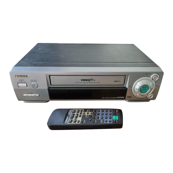
SERVICE MANUAL
VIDEO CASSETTE RECORDER
POWER REQUIREMENTS .................
POWER CONSUMPTION ...................
WEIGHT ..............................................
DIMENSIONS ......................................
OPERATING TEMPERATURE ...........
VIDEO RECORDING SYSTEM ..........
VIDEO SIGNAL SYSTEM ...................
VIDEO HEAD ......................................
USABLE CASSETTES ........................
CHANNEL COVERAGE ......................
RF OUTPUT ........................................
HORIZONTAL RESOLUTION ............
TIMER BACKUP .................................
TUNER SYSTEM ................................
TV SYSTEM ........................................
FAST-FORWARD TIME ......................
REWIND TIME ....................................
HI-FI FREQUENCY RESPONSE .......
HI-FI DYNAMIC RANGE .....................
HV-FX5100
BASIC TAPE MECHANISM : OVD-6
SPECIFICATIONS
230 V AC, 50 Hz
17W
3.5 kg (7.7 lbs.)
380 mm (W) x 267 mm (D) x
95 mm (H)
(15 x 10 5/8 x 3 3/4 in.)
5°C to 40°C
Rotary 2 head helical scanning
system
PAL colour system, 625 lines,
50 fields
Double azimuth 4 heads
VHS video cassette
UHF: 21 to 69
UHF channels between 23 and
69, 73 dBµ
240 lines (SP)
30 minutes
Frequency synthesized tuner
I
135 seconds with E-180 tape
108 seconds with E-180 tape
20 Hz-20 KHz
More than 75 dB
S/M Code No. 09-996-332-2N1
HI-FI WOW AND FLUTTER .............
TAPE SPEED ...................................
RECORDING/PLAYBACK TIME .....
VIDEO INPUT ...................................
VIDEO OUTPUT ..............................
VIDEO S/N .......................................
AUDIO INPUT ..................................
AUDIO OUTPUT ..............................
AUDIO TRACK .................................
•
Design and specifications are subject to change without
notice.
K
Less than 0.01% (nominal)
PAL
SP: 23.39 mm/sec
LP: 11.69 mm/sec
NTSC (playback only)
SP: 33.35 mm/sec
PAL
SP: 5 hours with E-300 tape
LP: 10 hours with E-300 tape
NTSC (playback only)
SP: 3 hours 30 minutes with
T-210 tape
1.0 Vp-p, 75 ohm, unbalanced
1.0 Vp-p, 75 ohm, unbalanced
53 dB (nominal)
SCART: –3.8 dBs, 50 Kohm
RCA: –3.8 dBs, 50 Kohm
SCART: –3.8 dBs, less than 1 Kohm
RCA: –3.8 dBs, less than 1 Kohm
3 tracks (Hi-Fi sound 2 tracks, Normal
sound 1 track)
Advertisement
Table of Contents

Related Manuals for Aiwa HV-FX5100


Summary of Contents for Aiwa HV-FX5100
- Page 1 HV-FX5100 SERVICE MANUAL VIDEO CASSETTE RECORDER BASIC TAPE MECHANISM : OVD-6 SPECIFICATIONS 230 V AC, 50 Hz HI-FI WOW AND FLUTTER ..... Less than 0.01% (nominal) POWER REQUIREMENTS ....POWER CONSUMPTION ....TAPE SPEED ........SP: 23.39 mm/sec WEIGHT ..........
-
Page 2: Table Of Contents
TABLE OF CONTENTS SPECIFICATIONS ................................COVER TABLE OF CONTENTS ..............................SERVICING NOTICES ON CHECKING ..........................IMPORTANT NOTICE ................................ DISASSEMBLY INSTRUCTIONS REMOVAL OF MECHANICAL PARTS AND P.C. BOARDS ................... B1-1 REMOVAL OF DECK PARTS ............................B2-1~B2-5 KEY TO ABBREVIATIONS ..............................C1-1, C1-2 SERVICE MODE LIST ............................... -
Page 3: Servicing Notices On Checking
SERVICING NOTICES ON CHECKING 1. KEEP THE NOTICES 3. PUT PARTS AND WIRES IN THE ORIGINAL POSITION AFTER ASSEMBLING OR WIRING As for the places which need special attentions, they are indicated with the labels or seals on the cabinet, chassis There are parts which use the insulation material such and parts. -
Page 4: Disassembly Instructions
DISASSEMBLY INSTRUCTIONS 1-3: DECK CHASSIS (Refer to Fig. 1-3) 1. REMOVAL OF MECHANICAL PARTS Remove the 3 screws 1. AND P.C. BOARDS Remove the screw 2. 1-1: TOP CABINET, FRONT CABINET AND Disconnect the following connectors: (CP1001, CP1002, OPERATION 1, 2 PCB (Refer to Fig. 1-1) CP1004, CP4001, CP4002 and CP4003). -
Page 5: Removal Of Deck Parts
DISASSEMBLY INSTRUCTIONS NOTE 2. REMOVAL OF DECK PARTS When you install the Tape Guide L, install as shown in the 2-1: TOP BRACKET (Refer to Fig. 2-1) circle of Fig. 2-3-B. (Refer to Fig. 2-3-B) Remove the 2 screws 1. Slide the 2 supports 2 and remove the Top Bracket. - Page 6 DISASSEMBLY INSTRUCTIONS 2-6: LINK ASS'Y (Refer to Fig. 2-6) 2-9: TENSION ASS'Y (Refer to Fig. 2-9-A) Set the Link Ass'y to the Eject position. Move the Inclined S Ass'y to the back side. Unlock the support 1 and remove the S Reel Stopper. Remove the (A) side of the Link Ass'y first, then remove the (B) side.
- Page 7 DISASSEMBLY INSTRUCTIONS 2-11: S REEL/T REEL ASS'Y (Refer to Fig. 2-11) NOTE Remove the Idler Ass'y. Do not touch the Pinch Roller. (Use gloves.) Remove the S Reel and T Reel Ass'y. When you install the Pinch Roller Ass'y, install as Remove the 2 Polyslider Washers 1.
- Page 8 DISASSEMBLY INSTRUCTIONS 2-15: AHC ASS'Y/CYLINDER UNIT ASS'Y (Refer to Fig. 2-15) Middle Gear Unlock the support 1 and remove the AHC Ass'y. E-Ring Remove the 3 screws 2. Remove the Cylinder Unit Ass'y. Main Cam NOTE Pinch Roller Cam When you install the Cylinder Unit Ass'y, tighten the screws from (1) to (3) in order while pulling the Ass'y Joint Gear Link Lever Spacer...
- Page 9 DISASSEMBLY INSTRUCTIONS 2-19: LOADING GEAR S/T ASS'Y (Refer to Fig. 2-19-A) 2-20: INCLINED S/T ASS'Y (Refer to Fig. 2-20) Remove the E-Ring 1 and remove the Main Loading Unlock the support 1 and remove the P4 Cover. Gear. Remove the S-S Brake Spring. Unlock the support 2 and remove the Loading Gear Remove the Capstan Brake Spring.
-
Page 10: Key To Abbreviations
KEY TO ABBREVIATIONS Audio/Control H.SW Head Switch Automatic Color Control Hertz Audio Erase Integrated Circuit Automatic Frequency Control Intermediate Frequency Automatic Fine Tuning Indicator AFT DET Automatic Fine Tuning Detect Inverter Automatic Gain Control Killer Amplifier Left Antenna Light Emitting Diode A.PB Audio Playback LIMIT AMP... - Page 11 KEY TO ABBREVIATIONS SYNC Synchronization SYNC SEP Sync Separator, Separation Transistor TRAC Tracking TRICK PB Trick Playback Test Point UNREG Unregulated Volt Voltage Controlled Oscillator Video Intermediate Frequency Vertical Pulse, Voltage Display V.PB Video Playback Variable Resistor V.REC Video Recording Visual Search Fast Forward Visual Search Rewind Voltage Super Source...
-
Page 12: Service Mode List
SERVICE MODE LIST This unit provided with the following SERVICE MODES so you can repair, examine and adjust easily. Method Operations Press both PLAY button and Initialization of the factory. CH UP button on the set for NOTE: Do not use this for the normal servicing. more than 2 seconds. -
Page 13: Preventive Checks And Service Intervals
PREVENTIVE CHECKS AND SERVICE INTERVALS The following standard table depends on environmental conditions and usage. Unless maintenance is properly carried out, the following service intervals may be quite shortened as harmful effects may be had on other parts. Also, long term storage or misuse may cause transformation and aging of rubber parts. Time 1,000 1,500... - Page 14 PREVENTIVE CHECKS AND SERVICE INTERVALS CLEANING NOTE 2. TAPE RUNNING SYSTEM After cleaning the heads with isopropyl alcohol, do not When cleaning the tape transport system, use the run a tape until the heads dry completely. If the heads gauze moistened with isopropyl alcohol. are not completely dry and alcohol gets on the tape, 3.
-
Page 15: Note For The Replacing Of Memory Ic
NOTE FOR THE REPLACING OF MEMORY IC If a service repair is undertaken where it has been required to change the MEMORY IC, the following steps should be taken to ensure correct data settings while making reference to TABLE 1. ADDRESS DATA ADDRESS... -
Page 16: Servicing Fixtures And Tools
SERVICING FIXTURES AND TOOLS (For 1 speed model) (For 2 speed model) JG002B Adapter JG005 Post Adjustment VHS Alignment Tape VHS Alignment Tape JG002E Dial Torque Gauge Screwdriver JG001E (TTV-P2) JG001C (TTV-P2) (10~90gf•cm) Part No. SV-TG0-030-000 JG001F (TTV-P1L) JG001D (TTV-P1L) JG002F (60~600gf•cm) (small) -
Page 17: Vcr Test Tape Interchangeability Table
VCR TEST TAPE INTERCHANGEABILITY TABLE There are two types of the new alignment tape CH-1B (for NTSC) and CH-2 (for PAL). On each tape four signals (1) - (4) are recorded for the times and in the order shown below. (1) : 8min. -
Page 18: Mechanical Adjustments
MECHANICAL ADJUSTMENTS 1-2: CONFIRMATION AND ADJUSTMENT OF TENSION 1. CONFIRMATION AND ADJUSTMENT POST POSITION Read the following NOTES before starting work. Set to the PLAY mode. • Place an object which weighs between 450g~500g on Adjust the Tension Adjust until the length from the edge the Cassette Tape to keep it steady when you want to of the Tension Arm to the standard line of the Main make the tape run without the Cassette Holder. -
Page 19: Confirmation And Adjustment Of Tape Running Mechanism
MECHANICAL ADJUSTMENTS 1-4: CONFIRMATION OF VSR TORQUE 2. CONFIRMATION AND ADJUSTMENT OF TAPE RUNNING MECHANISM Operate within 4~5 seconds after the reel disk begins to turn. Tape Running Mechanism is adjusted precisely at the Install the Torque Gauge (JG002F) and Adapter (JG002B) factory. - Page 20 MECHANICAL ADJUSTMENTS 2-2: CONFIRMATION AND ADJUSTMENT OF AUDIO/ 2-3: TAPE RUNNING ADJUSTMENT CONTROL HEAD (X VALUE ADJUSTMENT) When the Tape Running Mechanism does not work well, Confirm and adjust the height of the Reel Disk. adjust the following items. (Refer to item 1-1) Confirm and adjust the position of the Tension Post.
-
Page 21: Mechanism Adjustment Parts Location Guide
MECHANICAL ADJUSTMENTS 3. MECHANISM ADJUSTMENT PARTS LOCATION GUIDE 1. Tension Adjust P4 Post 2. Tension Arm T Brake Spring 3. Guide Roller T Reel Ass'y 4. P1 Post Idler Ass'y 5. Audio/Control Head S-S Brake Spring 6. X value adjustment driver hole S Reel D1-4... -
Page 22: Electrical Adjustments
ELECTRICAL ADJUSTMENTS Read and perform this adjustment when repairing the circuits or replacing electrical parts or PCB assemblies. 1. BASIC ADJUSTMENT CAUTION When replacing IC's or transistors, use only specified silicon grease (YG6260M). (To prevent the damage to IC's and transistors.) 1-1: PG SHIFTER CONDITIONS MODE-PLAYBACK... -
Page 23: Electrical Adjustment Parts Location Guide
ELECTRICAL ADJUSTMENTS 2. ELECTRICAL ADJUSTMENT PARTS LOCATION GUIDE T501 TP1002 TP1001 TU6001 TP4001 TP4002 J4501 SYSCON PCB D2-2... - Page 24 TROUBLESHOOTING GUIDE TROUBLESHOOTING GUIDE POWER DOES NOT TURN ON Does DISPLAY light ? Is F501 broken ? Replace F501. Is the voltage at collector Check IC1002. of Q507 about 5.6V ? Check the peripheral circuit to pin 14 of T501. Is the voltage at pin 20 of Check IC1002.
-
Page 25: Troubleshooting Guide
TROUBLESHOOTING GUIDE POWER SHUTS OFF Insert a cassette and press PLAY button. Check TAPE LOADING, Does it Power off in about LOADING BELT, DD MOTOR 3 seconds ? and CYLINDER MOTOR. Check REEL SENSOR and Does it Power off in BELT CAPSTAN. - Page 26 TROUBLESHOOTING GUIDE CYLINDER NOT ROTATING DURING PLAYBACK AND RECORDING Is the voltage at pin Check AT 12.6V line of 2 of CP1002 about POWER BLOCK. DC11.25V ? In playback, is the voltage at pin 5 of CP1002 about Check IC1002. DC1.52V ? Replace CYLINDER MOTOR.
- Page 27 TROUBLESHOOTING GUIDE AUDIO SHAKES Is AUDIO HEAD scratched ? Replace AUDIO HEAD. Is input level at pin 85 of Replace CAPSTAN DD UNIT. IC1002 about 0.4Vp-p ? In playback, is the voltage Check IC1002. at pin 4 of CP1003 2.6V ? Check AUDIO BLOCK.
- Page 28 TROUBLESHOOTING GUIDE CASSETTE TAPE IS NOT ACCEPTED Does WORM GEAR on Check FRONT LOADING CASSETTE LOADING GEARS and LOCKER. BLOCK activate ? When a cassette is inserted, Check LED and PHOTO is the voltage at pin 4 of SENSOR on SYSCON PCB. IC1002 0V ? When a cassette is inserted, Replace LOADING MOTOR.
- Page 29 TROUBLESHOOTING GUIDE WHEN INSERTING CASSETTE, IT EJECTS IMMEDIATELY Does another cassette Defective CASSETTE or go down ? CASSETTE LOADING BLOCK. When cassette is inserted, Check FRONT LOADING is the voltage at pins 4 and GEARS. 3 of IC1002 0V ? Check IC1002.
- Page 30 TROUBLESHOOTING GUIDE FF/REW DO NOT WORK Is the voltage changing at Check pins 9 and 10 of IC1002 pin 11 of IC1002 when lines. you press FF/REW ? Check DECK MECHANISM.
- Page 31 TROUBLESHOOTING GUIDE TAPE LOADING IS OK, BUT UNLOADS IMMEDIATELY Does CYLINDER Is the voltage at pin 2 Check Power circuit. rotate ? of CP1002 AT 12.6V ? In playback, is the voltage at pin 5 of CP1002 1.54V ? Replace CYLINDER UNIT. Does TP4001 feed Does PG PULSE signal appear at pin 86 of...
- Page 32 TROUBLESHOOTING GUIDE PLAYBACK PICTURE JITTERS HORIZONTALLY Is FG output level at pin 3 Replace CYLINDER MOTOR. of CP1002 about 4.0Vp-p? Is the voltage at pin 5 Replace IC1002. of CP1002 1.5V ? Replace CYLINDER MOTOR. PLAYBACK PICTURE SHAKES Is FG output level at Replace CYLINDER MOTOR.
- Page 33 TROUBLESHOOTING GUIDE AUTO TRACKING DOES NOT OPERATE By manual tracking, does the DC level at pin 84 Check CYLINDER UNIT. of IC4001 change ? Does the CTL PULSE In auto tracking, is the (about 4.6Vp-p) appear at Check CONTROL HEAD. voltage at pin 6 of IC1002 pin 97 of IC1002? more than DC 1V ?
- Page 34 TROUBLESHOOTING GUIDE WHEN IN PLAYBACK, FAST FORWARD OR REWIND MODE IS ACTIVATED, UNIT STOPS IMMEDIATELY Does CAPSTAN DD Refer to section "CAPSTAN MOTOR rotate ? DD MOTOR NOT ROTATING". Does the REEL SENSOR PULSE signal appear Check Q1001 and Q1002. at pins 79 and 80 IC1002 ? Replace IC1002.
- Page 35 TROUBLESHOOTING GUIDE PLAYBACK PICTURE JITTERS VERTICALLY Does tracking noise appear in the picture ? By adjusting the manual tracking UP/DOWN Check P/B ENVELOPE. buttons, will the noise disappear in the picture ? Are GUIDE POSTS Adjust GUIDE POST height. the right height ? Is PG SHIFTER Adjust PG SHIFTER.
- Page 36 TROUBLESHOOTING GUIDE NO PLAYBACK PICTURE Is the voltage at pins12, Is E-E appearing on Check Power circuit. 36, 61 and 90, 96 of the Monitor TV ? IC4001 5V ? Check VIDEO OUT LINE and IC4001. Check connection of the Is there FM signal at pins CYLINDER.
- Page 37 TROUBLESHOOTING GUIDE NO COLOR DURING PLAYBACK Does COMPOSITE signal appear at pin 52 Replace IC4001. of IC4001? Check Q4802 circuit. E-14...
- Page 38 TROUBLESHOOTING GUIDE PLAYBACK PICTURE IS NOISY (EVEN AFTER CLEANING HEADS) Is FM signal at pin 79 Check CYLINDER UNIT. of IC4001 270mVp-p ? Perform the interchangeable Is FM signal at pin6 of adjustment of DECK. IC1002 more than 1V ? Is VIDEO output at the emitter of Q4802 2Vp-p, Check IC4001 and Q4802.
- Page 39 TROUBLESHOOTING GUIDE NO COLOR DURING SELF RECORDING AND PLAYBACK Does VIDEO signal appear Replace J4501. at pin 31 of IC4001 ? Check VIDEO input circuit. Does color signal at Check IC4001. pin 52 of IC4001 ? Check Q4802 EMITTER. E-16...
- Page 40 TROUBLESHOOTING GUIDE NO NORMAL AUDIO ON PLAYBACK Does audio appear Refer to section "NO E-E". on E-E ? Does AUDIO signal appear at Check C4039 and peripheral pin 2 of IC4001 6mVp-p ? circuit. Does AUDIO signal appear at Replace IC4001. pin 11 of IC4001 1Vp-p ? Check AUDIO HEAD for debris or stains.
- Page 41 TROUBLESHOOTING GUIDE CAPSTAN DD MOTOR NOT ROTATING In playback is the Check POWER circuit. voltage at pin 5 of CP1003 12V ? Is the voltage at pin 8 of CP1003 5V ? In playback, check the voltage at pin 3 of Replace IC1002.
- Page 42 TROUBLESHOOTING GUIDE AUDIO CAN NOT BE RECORDED Is BIAS level O.K Is the voltage at pin 2 Check POWER circuit. at L4005 ? of L4005 5.8V ? Is the voltage at pin 29 Replace IC1002. of IC1002 about 5V ? L4005 is broken or shorted.
- Page 43 TROUBLESHOOTING GUIDE CASSETTE IN AND DOWN, UNIT HAS NO FUNCTIONS Does mode indicator Check LOADING MOTOR appear in Display ? and the peripheral parts. Does VCR operate with Check IC1002. the remote control ? Check Operation PCB. E-20...
- Page 44 TROUBLESHOOTING GUIDE RECORDING MECHANISM WORKS,BUT NO VIDEO RECORDED FROM INPUT JACK OR TUNER Check the circuit from VIDEO Does VIDEO signal input jack to IC4001, from Tuner appear at pin 31 of Pack to IC4001. IC4001 ? Does the VIDEO signal Replace IC4001.
- Page 45 TROUBLESHOOTING GUIDE NO E-E(VIDEO AND AUDIO FROM TUNER) Are the plugs connected Disconnect the plugs from the to the VIDEO/AUDIO VIDEO/AUDIO input jacks. input jacks ? Do the voltages appear at each terminal PB(5V), Check Power Block. TU(32V) and B+(5V) of TU6001 ? CHECK AUDIO CHECK VIDEO...
- Page 46 TROUBLESHOOTING GUIDE NO E-E AUDIO (MONO) Is the voltage at pin Check POWER BLOCK. 40 of IC5501 5V ? Is the voltage at pin Check POWER BLOCK. 34 of IC5501 12V ? Does AUDIO signal Check J4501 and peripheral appear at pins 6 and 7 circuit.
- Page 47 TROUBLESHOOTING GUIDE NO E-E AUDIO (STEREO) Refer to section " NO E-E Does audio appear AUDIO (MONO) ". on E-E ? Check the circuit between IC5501 to J4501. E-24...
- Page 48 TROUBLESHOOTING GUIDE NO TUNER AUDIO (MONO) Refer to section " NO E-E Does audio appear AUDIO (MONO) ". on E-E ? Does AUDIO signal Check pin 21TU6001. appear at pin 38 of IC6601 ? Does AUDIO signal Replace IC6601. appear at pins 1 and 2 of IC6601 ? Does AUDIO signal Replace IC5501.
- Page 49 TROUBLESHOOTING GUIDE NO TUNER AUDIO (STEREO) Does signal appear Reploce TU6001. at pin 25 of IC6601 ? Refer to section "NO TUNER AUDIO (MONO)". E-26...
- Page 50 TROUBLESHOOTING GUIDE NO PB AUDIO (Hi-Fi) Does audio appear Refer to section " NO E-E on E-E ? AUDIO (STEREO) ". Does audio appear Refer to section " NO NORMAL on PB ? AUDIO ON PLAYBACK ". Is the voltage at pin Replace IC1002.
- Page 51 TROUBLESHOOTING GUIDE Hi-Fi AUDIO CANNOT BE RECORDED Does audio appear Refer to section " NO E-E on E-E ? AUDIO (MONO) ". Is the voltage at pin 44 of Replace IC1002. IC5501 hight ? Replace IC5501. E-28...
-
Page 52: Ic Descriptions
IC DESCRIPTIONS OEC7035A Pin No. Pin Name Description AFT-SC AFT S Curve input for tuner. AGC-DET Input of CASS DOWN, TAB switch and setting of service mode. Tape end sensor input signal. Tape start sensor input signal. RF SW/A-ENV Ground. V-ENV Input terminal of video RF envelope. - Page 53 IC DESCRIPTIONS OEC7035A Pin No. Pin Name Description POWER ON L O For control the user power switch ON/OFF. O Not used. ONE TOUCH PB O Control the LED for the ONE TOUCH PLAYBACK. PELI CTL Control the 21 pin IC output. O Not used.
-
Page 54: Servo Timing Chart
SERVO TIMING CHART IC1001 (OEC7035A) DPG * 6 PIN DFG *7 PIN H. SW. P CH 1 CH 2 ! 8 PIN V-SYNC (E-E) * 4 PIN REC CTL (REC) ( 7 PIN V-SYNC (TRICK PB) ! 3 PIN • WAVEFORM CHANGES DEPENDED ON THE TAPE SPEED... -
Page 55: System Switch Mode
SYSTEM SWITCH MODE : CAPSTAN FWD ROTATING SLOW : SETTING SPEED TO SERVO LOADING DIRECTION DIRECTION : MECHANICAL MOVEMENT AND CAPSTAN ROTATING (FWD) : CAPSTAN RVS ROTATING : MECHANICAL MOVEMENT (NO CAPSTAN ROTATING) DIRECTION EJECTION UNLOADING STP3 F. SLOW PB/STP STP2 FF/REW LIGHT... -
Page 56: Semiconductor Base Connections
SEMICONDUCTOR BASE CONNECTIONS DIODE CATHODE CATHODE ANODE ANODE 11DF2N-TA2B2 11EQS04N-TA1B2 RGP15D-G23 1SS244T-77 MA367-(TX) SID1050CM SLZ-345B-02-T1 1SS133T-77 11ES1N-TA1B2 GMA-02-BT 1N4005E-G23 MTZJ12B T-77 RD12FB-T7 MTZJ15B T-77 SB340L-6737 MTZJ27B T-77 MTZJ33B T-77 MTZJ4.7B T-77 44PIN 30PIN 8PIN 3PIN 8PIN 5PIN BU2979K LC74775M M24C08-BN6 NJM431L BA6955AN STR-F6552 TDA9605H... -
Page 57: Y/C/Audio/Head Amp
Y/C/AUDIO/HEAD AMP BLOCK DIAGRAM X4001 4.433619MHz CP4001 EP/LP-CH2(L) EP/LP COM EP/LP-CH1(R) SP-CH2(L) 2MLPF SP-COM CTL TRAP 6db AMP fh HPF 6db AMP SP-CH1(R) HF2(L) CLPF C SQUELCH DELAY CLPF CLEAR FH COM TRAP MAIN MAIN SYNC CONV2 HF1(R) CONV1 SQUELCH TUNER/HI-FI/ HF COM 21PIN/OSD/... -
Page 58: System Control/Servo/Timer
SYSTEM CONTROL/SERVO/TIMER BLOCK DIAGRAM LOADING MOTOR DRIVER IC1001 BA6955AN SYSCON/SERVO/TIMER IC1002 OEC7035A CP1004 HEATER SW HEATER SW POWER FAIL P.FAIL POWER LDM FWD LDM - DECk POWER ON-H POWER ON-H A LDM RVS LDM + CAP HI-H CAP HI-H REMOCON REMOCON TUNER/HIFI/ A.ENV... -
Page 59: Tuner/Hifi/21Pin/Osd/Vps/Nicam
TUNER/HIFI/21PIN/OSD/VPS/NICAM BLOCK DIAGRAM HIFI IC5501 TDA9605H RECORD LUMINANCE SIGNAL PLAYBACK LUMINANCE SIGNAL J4204 1.3M/1.4M NOISE 1.3M/1.4M RECORD COLOR SIGNAL REDUCTION PLAYBACK COLOR SIGNAL HF LPF J4501 TUNER VIDEO SIGNAL AUDIO SIGNAL (REC) 1.7M/1.8M AUDIO SIGNAL (PB) 1.7M/1.8M HF LPF INPUT SWITCH NOISE REDUCTION... -
Page 60: Power Block Diagram
OPERATION BLOCK DIAGRAM V651 7-MT-201G 26 25 HEATER_DC + POWER HEATER_DC - CH.UP CH.UP_SW IC651 POWER Q601 BU2979K OTPB SW STILL/PAUSE FIP DRIVER D601 SYSCON/ OTPB OS651 SERVO/TIMER CH.DOWN REMOCON STOP/EJECT KEY-A REC/OTR FF/CUE PLAY REW/REV POWER BLOCK DIAGRAM D525 CAP VCO Q508 Q509... -
Page 61: Deck Schematic Diagram
DECK SCHEMATIC DIAGRAM LOADING MOTOR M101 (DECK PCB) S105 BOT SENSOR Q101 S106 RPT-38PB113 S101 S102 S103 S104 FROM/TO SYSCON/SERVO/TIMER CP101(CP1004) 52044-0445 LDM+ LDM- FROM/TO SYSCON/SERVO/TIMER CP102(CP1001) 173979-2 EOT SENSOR Q102 RPT-38PB113 PCB550 VE8851 NOTE: NOTE: THIS SCHEMATIC DIAGRAM IS THE LATEST AT THE TIME THE DC VOLTAGE AT EACH PART WAS CAUTION: SINCE THESE PARTS MARKED BY... -
Page 62: Operation Schematic Diagram
OPERATION SCHEMATIC DIAGRAM (OPERATION 2 PCB) (OPERATION 1 PCB) OTPB SW Q601 DTA143ES TO DISPLAY FROM/TO DISPLAY CD601(CP651) R601 R602 R603 R604 R605 KEY A CD602(CP652) 3.3K 2.7K 3.9K 6.8K CH.UP_SW CH25082A OTPB CH23042A CH.UP_SW C601 AT+5V 470P B R606 KEY-A 1.5K R608... - Page 63 PRINTED CIRCUIT BOARDS OPERATION 1 DECK OPERATION 2 CP101 CP102 CD601 SW602 CD602 Q601 SW608 SW607 Q101 Q102 D601 SW609...
-
Page 64: Printed Circuit Boards (Operation 1/2/Deck
PRINTED CIRCUIT BOARDS SYSCON R4038 Q4005 C6005 R1014 Q1009 R4005 C4518 R4529 R4004 C4533 R4524 C6010 Q4505 R4018 Q4506 R4504 C4524 C4512 C4098 R4502 R4011 R4029 C5521 C4034 R4010 C4050 W890 C4104 C4027 C4072 C4523 IC4501 C5507 C4064 C4103 C4011 R4014 R5516 Q4008... - Page 65 PRINTED CIRCUIT BOARDS SYSCON D4003 W185 W157 Q4003 W807 R4516 W217 R1034 R4507 L4003 W224 R1002 W002 R4515 J4204 L4512 D1002 Q4004 Q4007 C4024 W011 Q1008 C4213 R4204 C6013 CP506 W212 R4203 W003 J4501 CP4002 W025 Q4006 W131 W119 C503 IC1001 R4007 R4512...
- Page 66 PRINTED CIRCUIT BOARDS SYSCON D4003 W185 W157 Q4003 W807 R4516 W217 R1034 R4507 R4038 Q4005 L4003 C6005 R1014 W224 R1002 Q1009 W002 R4005 C4518 R4529 J4204 R4515 R4004 D1002 L4512 Q4004 Q4007 C4024 W011 Q1008 C4533 C4213 C6013 R4204 CP506 W212 R4203 W003...
-
Page 67: Y/C/Audio/Head Amp Schematic Diagram
Y/C/AUDIO/HEAD AMP SCHEMATIC DIAGRAM (SYSCON PCB) FROM/TO SYSCON/SERVO/TIMER VV-H V.H_SW PICTURE_CTL NA_REC-H DUMMY_V.SYNC SYNC A_MUTE/TRICK-H IIC_DATA IIC_CLK ENV.DET CTL+ H.SW V.ENV R4033 CTL- TP4001 TP4002 Y/C/AUDIO/CCD/H.AMP C4011 IC4001 FROM/TO 21PIN/OSD/VPS HA118217F 0.001 B 2FSC R4045 C GND V.H_SW CVCC SYNC NTSC/PAL N-P CONT SWD_VIDEO_IN... -
Page 68: System Control/Servo/Timer Schematic Diagram
SYSTEM CONTROL/SERVO/TIMER SCHEMATIC DIAGRAM FROM/TO POWER HEATER_SW HEATER_SW (SYSCON PCB) CAP_HI-H POWER_FAIL POWER_FAIL CAP_VCO AT+5V-A D1007 D1006 1N4005E AT+5.8V 1SS133 POWER_ON-H AT+12.6V P.CON+5V (S/S) (CYL) (CAP) (LDM) IC1001 BA6955AN LOADING MOTOR DRIVER FROM/TO Y/C/A/H.AMP CONTROL LOGIC VV-H V.H_SW POWER PICTURE_CTL SAVE NA_REC-H SERVICE... -
Page 69: 21Pin/Osd/Vps Schematic Diagram
21PIN/OSD/VPS SCHEMATIC DIAGRAM (SYSCON PCB) AT+5V DEC_V_IN DEC_V_OUT PERI_CTL-L SCRANBLE R4524 L4506 R4512 Q4501 DEC_A_IN-L DTC114EKA 22uH R4502 L4501 R4504 DEC_A_OUT-L 22uH CLAMP REGULATOR MUTE GAIN CTL SERIAL CONTROL SW1-L L4509 R4511 DEC_A_IN-R SW2-L SW3-L 22uH R4501 L4502 R4505 DEC_A_OUT-R CLAMP CLAMP CLAMP... -
Page 70: Tuner/Hifi Schematic Diagram
TUNER/HIFI SCHEMATIC DIAGRAM (SYSCON PCB) TU6001 L6001_1 TMDB2-103A W881 P.CON+5V-A 220uH R6005 RF_CONV.A_OUT A.IN IIC_DATA L6002 P.CON+5V 100uH IIC_CLK C5504 C6012 RF_CONV.V V.IN R5504 6.3V +32V R6011 C5505 R5512 TU(MD) AGC_DET R6016 0.1 B R6006 Q6001 L5502 C5525 10.5 active s-by Vref Iref Supply... -
Page 71: Power Schematic Diagram
POWER SCHEMATIC DIAGRAM (SYSCON PCB) D512 11DF2N TO TUNER/HIFI R517 D513 +32V D504 1N4005E 390 1/4W P.CON+5V-A 1N4005E P.CON+5V CD501 AT+12V D502 06635817 CP506 (AUDIO) AC230V_50Hz 1-1123724-2 1N4005E (TUNER) BLUE FH501 FH502 BLUE (HIFI) D503 EYF-52BC EYF-52BC BROWN 1N4005E L502_1 BROWN F501 D505... -
Page 72: Display Schematic Diagram
DISPLAY SCHEMATIC DIAGRAM (SYSCON PCB) V651 7-MT-201GA V651 (7-MT-201GA) ANODE CONNECTION col2 col1 SLPM col2 col1 OS651 PNA4612M00YB Vout C651 6.3V -23.3 -14.9 -18.9 -14.6 -14.6 -15.0 -19.5 -19.3 -21.3 -11.3 SEG10 -17.5 FL_CS 33 SEG9 SEG11 -21.3 FL_S_CLK SEG12/GRID11 FIP DRIVER -26.2 IC651... -
Page 73: Nicam Schematic Diagram
NICAM SCHEMATIC DIAGRAM (SYSCON PCB) FROM/TO SYSCON/SERVO/TIMER IIC_DATA IIC_CLK W834 L6601 100uH 0607 FROM POWER P.CON+5V-A C6613 FROM/TO TUNER/HIFI 0.1 B SIF/TU_A_[R] TUNER_AUDIO_R W863 TUNER_AUDIO_L TU_A_OUT R6601 R6610 R6614 W803 W869 8.2K VSSD4 VSSA2 1 OUTL 23 SIF2 W823 ADDR2 2 OUTR 24 V REF1 C6603... -
Page 74: Interconnection Diagram
INTERCONNECTION DIAGRAM F/E HEAD H5002 HALL MAIN ROTOR SENSOR COIL MAGNET FG SENSOR HALL HALL SWITCH LOGIC CD501 AC230V50Hz CP506 CP1003 BLUE MOTOR GND BROWN I LIMIT VCO(12V) J4501 VCR/DECODER CAP.M F/R A.OUT(R) DEC.A.OUT(R) VCC(5V) CAPSTAN DD UNIT A.IN(R) DEC.A.IN(R) M2001 A.OUT(L) DEC.A.OUT(L) -
Page 75: Waveforms
WAVEFORMS Y/C/AUDIO/HEAD AMP REC, PB 17 REC, PB 0.5V 10U/div 10V 5U/div 0.5V 0.5V/div 1V 0.5s/div REC, PB REC, PB 2 PB 18 REC, PB 200mV 0.5V/div 1V 5U/div 200mV 10U/div 1V 0.5s/div SYSCON/SERVO/TIMER POWER ON REC, PB REC, PB 100mV 50T/div 1V 5V/div 1V 5U/div... -
Page 76: Mechanical Exploded View
MECHANICAL EXPLODED VIEW TU6001 PCB010 (SYSCON PCB ASS'Y) PCB280 (OPERATION 2 PCB ASS'Y) PCB270 (OPERATION 1 PCB ASS'Y) L1-1... -
Page 77: Mechanical Replacement Parts List
MECHANICAL REPLACEMENT PARTS LIST REF. NO. PART NO. DESCRIPTION Q'TY S4-D40-4B7-200 CAB,FRONT ASS'Y S0-1WP-A03-480 HOLDER,DECK(A) S0-4WP-A00-070 HOLDER,DECK(R) S2-344-900-130 BADGE,BRAND S3-5WP-D06-050 BUTTON,FF S3-5WP-D06-060 BUTTON,REW ----- SHIELD,CASE HEAD AMP ----- SHIELD,COVER HEAD AMP ----- SPR,EARTH HEAD AMP ----- SPR,EARTH HEAD AMP S3-5WP-D06-070 BUTTON,BASE S5-5WP-A00-090 PLATE,COVER POWER... -
Page 78: Chassis Exploded View (Top View)
CHASSIS EXPLODED VIEW (TOP VIEW) M2003 UN4001 H5001 H5002 M101 PCB550 (DECK PCB ASS'Y) NOTE: Applying positions AA, AB, AC and BA for the CLASS PART NO. MARK grease or oil are displayed for this section. GREASE G-555G Check if the correct grease or oil is applied for each position. -
Page 79: Chassis Exploded View (Bottom View)
CHASSIS EXPLODED VIEW (BOTTOM VIEW) M2001 NOTE: Applying positions AA, AB, AC and BA for the CLASS PART NO. MARK grease or oil are displayed for this section. GREASE G-555G Check if the correct grease or oil is applied for each position. -
Page 80: Chassis Replacement Parts List
CHASSIS REPLACEMENT PARTS LIST REF. NO. PART NO. DESCRIPTION Q'TY REF. NO. PART NO. DESCRIPTION Q'TY S5-OA5-000-220 AHC ASS'Y S5-OP9-006-860 TAPE GUIDE R S5-OP2-002-700 BELT,CAPSTAN S5-OP9-006-870 COVER,SENSOR L S5-OP9-006-890 LEVER,REC S5-OP9-006-880 LEVER,FLAP S5-OP5-000-830 BASE,AC HEAD S5-OP9-006-900 CASS HOLDER S5-OP8-003-240 SPR,AC HEAD S5-OP9-006-910 LOCKER,L S5-OA0-002-970 MAIN CHASSIS ASS'Y S5-OP9-006-920 LOCKER,R... -
Page 81: Electrical Replacement Parts List
ELECTRICAL REPLACEMENT PARTS LIST REF.NO. PART NO. DESCRIPTION REF.NO. PART NO. DESCRIPTION SYSCON PCB ASS'Y *** CAPACITORS *** *** RESISTORS *** C4079 87-015-075-040 CAP,E 10-16V C4081 87-010-077-080 CAP,E 33UF-10V ! R502 S3-118-A01-0J0 RES,M/O 1-2W C4084 87-015-695-080 CAP,E 1-50V ! R516 87-029-174-090 RES,FUSE 1-1/4W C4090... - Page 82 ELECTRICAL REPLACEMENT PARTS LIST REF.NO. PART NO. DESCRIPTION REF.NO. PART NO. DESCRIPTION *** DIODES *** *** COILS *** D528 S2-LXE-658-000 DIODE,1N4005E-G23 B502 S2-46T-035-840 CORE,BEADS BF40DTA-3.5 D530 S2-LXE-658-000 DIODE,1N4005E-G23 B503 S2-46T-035-840 CORE,BEADS BF40DTA-3.5 D531 S9-7U0-120-1B0 ZENER,MTZJ12B T-77 B504 S2-46T-035-840 CORE,BEADS BF40DTA-3.5 D532 S2-8TE-QS0-400 DIODE,11EQS04N-TA D1001...
- Page 83 ELECTRICAL REPLACEMENT PARTS LIST REF.NO. PART NO. DESCRIPTION *** CRYSTAL & CERAMIC OSCILLATORS *** X1001 S0-0CT-012-070 X'TAL,HC-49/U-S X1002 S0-0D3-2R8-010 X'TAL,32.768K X4001 S0-0CF-4R4-010 X'TAL,HC-49/U X6601 S0-0CT-024-010 X'TAL,HC-49/U *** TUNER *** ! TU6001 S1-626-070-100 RF UNIT,TMDB2-103A *** FUSES *** ! F501 S8-0PT-1R6-020 FUSE,21801.6 FH501 S6-710-T00-060 HOLDER,FUSE EYF-52B...
- Page 84 2–11, IKENOHATA 1–CHOME, TAITO-KU, TOKYO 110-8710, JAPAN TEL:03 (3827) 3111 Printed in Singapore 920074...