Table of Contents
Advertisement
Quick Links
Advertisement
Table of Contents

Related Manuals for Wolf Vulcan VCCB25


Summary of Contents for Wolf Vulcan VCCB25
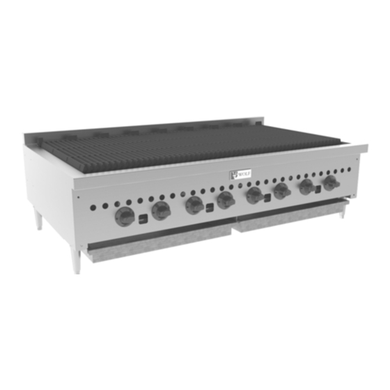
- Page 1 INSTALLATION & OPERATION MANUAL GAS CHARBROILERS MODELS VCCB25 VCCB36 VCCB47 VCCB60 VCCB72 VCCB47 SCB25 SCB36 SCB47 SCB60 SCB72 SCB47 RETAIN THIS MANUAL FOR FUTURE USE © ITW Food Equipment Group, LLC 3600 North Point Blvd. Baltimore, MD 21222 FORM F-36952 (3-12)
-
Page 2: Important For Your Safety
IMPORTANT FOR YOUR SAFETY THIS MANUAL HAS BEEN PREPARED FOR PERSONNEL QUALIFIED TO INSTALL GAS EQUIPMENT, WHO SHOULD PERFORM THE INITIAL FIELD START-UP AND ADJUSTMENTS OF THE EQUIPMENT COVERED BY THIS MANUAL. POST IN A PROMINENT LOCATION THE INSTRUCTIONS TO BE FOLLOWED IN THE EVENT THE SMELL OF GAS IS DETECTED. -
Page 3: Installation
A grease drawer is provided to collect fat run-off; it opens to the front for inspection or drain-off. Model Number of Burners BTU/hr Input Rating VCCB25, SCB25 58,000 VCCB36, SCB36 87,000 VCCB47, SCB47... - Page 4 LOCATION The installation location must be kept free and clear of combustibles. Do not obstruct the flow of combustion and ventilation air. DO NOT install the charbroiler adjacent to open burners or fryers. Sufficient air should be allowed to enter the room to compensate for the amount of air removed by any ventilating system and for combustion of the gas burners.
- Page 5 In Canada: 1. Local codes. 2. CAN/CSA-B149.1 Natural Gas Installation (latest edition) 3. CAN/CSA-B149.2 Propane Installation Code (latest edition), available from the Canadian Gas Association, 178 Rexdale Blvd., Etobicoke, Ontario, Canada M9W 1R3 BURNERS, RADIANTS, AND TOP GRATES The top grates are shipped flat (top-side down) from the factory. For broiling, the top grates can be left in the flat position or reversed so they slope forward for grease run-off.
-
Page 6: Component Parts
COMPONENT PARTS The charbroiler comes with several standard parts as illustrated. Each can be easily removed and installed easily by hand for cleaning and maintenance. Note that the Burner and Deflector are an assembly and are NOT designed to be disassembled. -
Page 7: Gas Pressure Regulator Installation
An adequate gas supply is necessary. Undersized or low pressure lines will restrict the volume of gas required for satisfactory performance. A minimum supply pressure of 7" W.C. for natural gas and 11" W.C. for propane gas is recommended. With all units operating simultaneously, the manifold pressure on all units should not show any appreciable drop. -
Page 8: Operation
CASTER EQUIPPED CHARBROILERS Charbroilers mounted on stands with casters must use a flexible connector (not supplied) that complies with the Standard for Connectors for Movable Gas Appliances, ANSI Z21.69 • CSA 6.16 and a quick-disconnect device that complies with the Standard for Quick- Disconnect Devices for use With Gas Fuel, ANSI-Z21.41 •... -
Page 9: Pilot Adjustment
LIGHTING THE GAS PILOT 1. Turn main gas shut‐off valve and the individual burner gas valves OFF. Pilot Wait 5 minutes. 2. Remove the top grates and radiants. Turn the main gas shut‐off valve ON. Light pilots using a lit taper. See Fig. 6. Adjust the pilot valve screw until the pilot flame has a slight yellow tip. 3. To light the burners, turn the individual burner valves ON. 4. If the burners fail to light, turn all valves and the main gas shut‐off to the OFF position and contact an FIG. 6 authorized service agency. PILOT ADJUSTMENT Using a flathead screwdriver, turn the slotted hex-head pilot adjustment Pilot Adjustment Screws screw clockwise to decrease the flame, and counter clockwise to increase the flame. -
Page 10: Maintenance
CLEANING Scrape top grates during broiling with a wire brush to keep the grates clean. Do not allow debris to accumulate on the grates. Top grates may be immersed in strong commercial cleaning compound overnight. In the morning, rinse with hot water to remove any residues of cleaning compound. -
Page 11: Troubleshooting
TROUBLESHOOTING Uneven heating, sides burning A. Burner valves improperly adjusted B. Fluctuating gas pressure C. Improperly adjusted burner Too much top heat A. Burner valves adjusted too high B. Faulty ventilation C. Overrated gas pressure D. Improperly adjusted burner Uneven heat side to side A. - Page 12 PLATE RAIL ACCESSORY INSTALLATION The charbroiler and its parts are hot. Use care when operating, cleaning or servicing the charbroiler. 1. Brackets are reversible – align holes on bottom of plate with slots on the bracket as shown. Attach parts using the included self-tapping screws.
- Page 13 SPLASH ACCESSORY INSTALLATION The charbroiler and its parts are hot. Use care when operating, cleaning or servicing the charbroiler. BACK VIEW ...
- Page 14 NOTES...
- Page 15 REMARQUES...
- Page 16 REMARQUES VUE ARRIÈRE gril. entretenez nettoyez employez, vous lorsque attention Faites chauds. sont pièces gril ÉCLABOUSSURES CONTRE PAROI ACCESSOIRES INSTALLATION...
- Page 17 CONDUITE. BOUCHON PLAQUE ACCOUPLER ATTACHER montage supports travers à réinsérer avant panneau Enlever avant. panneau dans avec fentes aligner gril conduite bouchon plaque l'assemblage Accoupler SUPPORT PLAQUE TROUS FENTES côté. l’autre pour Répéter incluses. autotaraudeuses utilisant pièces Attacher qu’illustré. support trouvant fentes avec...
-
Page 18: Dépannage
bouchée régulateur d'air prise Vérifiez varie pression brûleur touchent flammes élévé trop sont jusqu’à brûleurs obturateurs Fermez brûleurs flammes bleues redeviennent jaunes sont flammes brûleurs jusqu’à brûleurs obturateurs Ouvrez flammes basse pression d’allumage veilleuse l’orifice Obstruction circulation permettre pour d’allumage veilleuse d’allumage Réglez... -
Page 19: Entretien
série. numéro modèle numéro l'appareil d'identification plaque disponibles être devraient suivants renseignements service, pour appelez vous Lorsque www.vulcanequipment.com. consultez pièces, services bureaux liste Pour équipement. nécessaire réglage tout réparation toute pour local clientèle à service votre Contactez SERVICE coincement. signe premier dès élevées... - Page 20 l'utiliser. avant cuisson l’huile avec grilles Frottez minutes. pendant gril Préchauffez GRIL PRÉCHAUFFAGE rallumer.) avant fermées sont brûleurs individuelles soupapes toutes (Assurez-vous gaz. principal d’arrêt robinet Fermez complètement fermer Pour VEILLEUSES BRÛLEURS FLAMMES COMPLÈTEMENT FERMER POUR Fig. Fig. Voir flamme. augmenter pour montre...
- Page 21 température. augmentation provoque ventilation bloque cela grilles, mise viande Lorsque grilles. travers à passent brûleurs générés chaleur combustion produits Tous évacuation. sans appareil gril brûleurs. flamme éliminées être devraient jaune traces Toutes bleue. flamme d'offrir afin individuellement réglés être doivent brûleurs principaux d'air...
- Page 22 kPa) (3,45 ½ à supérieure d’alimentation pression à connecté être moment aucun à devrait gril propane. pour à naturel pour à être devrait régulateur) amont minimum d'alimentation pression Fig. Fig. (Fig. droite haut vers dirigés soient réglage d’aération bouchon avec placé...
- Page 23 tuyauterie. à pâte toute saleté d'obstructions, libres propres soient conduites Assurez-vous pression. vérifier pour brûleurs rampe taraud Utilisez propane. pour d’eau) (colonne — naturel pour d’eau) (colonne à établis sont paroi mince orifices gaz. d’alimentation connexion effectuez vous lorsque gril l’extérieur à...
- Page 24 Fig. supérieures Grilles Radiants Brûleurs Fig. Voir supérieures. grilles radiants Remontez brûleurs. tenir pour livraison durant utilisés supports enlevez Examinez fonte. radiants grilles Enlevez gras. d’écouler afin l’avant vers penchent qu’elles pour inversées plat à laissées être peuvent supérieures grilles gril, cuisson Pour...
- Page 25 CMR. à conforme être doit d’échappement potentielle moyenne avec réglage clef d’une muni d'échappement système ventilation hotte à grâce aérés d'utilisation appareils Tous Massachusetts l’État Dans REMARQUE 02169-7471 Quincy, Park Batterymarch NFPA, Council, Standards Secretary 20001 Washington, Capital à Z223, Committee Standards Accredited...
- Page 26 Immédiatement DÉBALLAGE INSTALLATION 188,500 SCB72 VCCB72, 159,500 SCB60 VCCB60, 116,000 SCB47 VCCB47, 87,000 SCB36 VCCB36, 58,000 SCB25 VCCB25, BTU/h calorifique Débit brûleurs Nombre Modèle vider. vérifier pour devant s’ouvre gras; l’écoulement recueillir afin fourni graisse à tiroir l'avant.
- Page 27 APPAREIL. FONCTIONNER FAIRE TENTER COURANT, PANNE équipement. servir d’installer avant d’entretien d’emploi d’installation, instructions minutieusement Lire mort. blessure matériel, dommage causer peut inapproprié entretien service modification, ajustement, installation, APPAREIL. AUTRE TOUT APPAREIL PROXIMITÉ À INFLAMMABLES LIQUIDES VAPEURS AUTRES L’ESSENCE UTILISER ENTREPOSER SÉCURITÉ...
- Page 28 (3-12) F-36952 FORMULAIRE 21222 Baltimore, Blvd. Point North 3600 FUTURE UTILISATION POUR MANUAL GARDER Group, Equipment Food © SCB47 SCB72 SCB60 SCB47 SCB36 SCB25 VCCB47 VCCB72 VCCB60 VCCB47 VCCB36 VCCB25 MODÈLES GRILS POUR D’EMPLOI D’INSTALLATION MANUEL...