Star Micronics TSP1000 Series Product Specifications Manual
Hide thumbs
Also See for TSP1000 Series:
- User manual (156 pages) ,
- Paper manual (2 pages) ,
- Supplementary manual (2 pages)

Related Manuals for Star Micronics TSP1000 Series


Summary of Contents for Star Micronics TSP1000 Series
- Page 1 Product Specifications Manual TSP1000 Series Rev. 0.00 Star Micronics Co., Ltd. Special Products Operating Division...
-
Page 2: Table Of Contents
Table of Contents GENERAL DESCRIPTION ........................1-1 BASIC SPECIFICATIONS ......................... 2-1 Printing Specifications..........................2-1 Character Specifications and Bar Code Specifications ................2-2 2-2-1 STAR Line Mode.....................................2-2 2-2-2 STAR Page Mode...................................2-3 2-2-3 ESC/POS Mode....................................2-4 Paper Specifications (Thermal Paper) ....................2-5 Black Mark Specifications ........................2-7 Auto-cutter Specifications ........................ - Page 3 12-2-5 Status (Nibble Mode)................................12-2 12-3 Serial RS-232C Interface (D-SUB 25 Pin/D-SUB 9 Pin) ..............12-3 12-3-1 Specification ....................................12-3 12-3-2 Connector....................................12-3 12-3-3 Communication Protocols................................12-5 12-4 USB Interface (B Type) ........................12-7 12-4-1 Specifications .....................................12-7 12-4-2 Connector....................................12-7 12-5 Network Interface (RJ-45) ......................... 12-7 12-5-1 Specification ....................................12-7 12-5-2...
-
Page 4: General Description
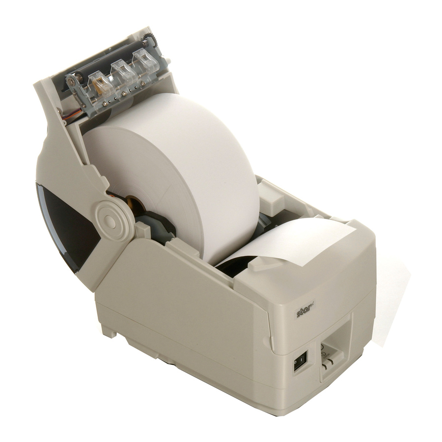
GENERAL DESCRIPTION The TSP1000 series is a direct thermal printer mechanism having a clam-shell configuration that employs a thermal line dot printing system. Model Name Display Directions TSP10 Other: None = Standard GRY: Case color is gray Power Specifications: 24: DC 24 V... -
Page 5: Basic Specifications
(Paper feed amount at one motor step (2-2 phase excitation) Line Width: STAR Mode: 4 mm or 3 mm ESC/POS Mode: 4.23 mm (1/6 inch) Can be set by command. Print Head: Line thermal head Emulation: STAR line mode STAR page mode ESC/POS mode TSP1000 Series Product Specifications... -
Page 6: Character Specifications And Bar Code Specifications
Note 1: JIS first and second standard Chinese characters conform to JISx0208-1990 and JISx0208-1997. They correspond to SHIFT-JIS code. Note 2: Conforms to GB2312 Bar Codes Bar Code Types Primary Bar Codes UPC-A UPC-E JAN/EAN8 JAN/EAN13 CODE39 CODE93 CODE128 CODABAR (NW-7) Secondary Bar Codes PDF417 TSP1000 Series Product Specifications... -
Page 7: Star Page Mode
Note 1: JIS first and second standard Chinese characters conform to JISx0208-1990 and JISx0208-1997. They correspond to SHIFT-JIS code. Note 2: Conforms to GB2312 Bar Codes Bar Code Types Primary Bar Codes UPC-A UPC-E JAN/EAN8 JAN/EAN13 CODE39 CODE93 CODE128 CODABAR (NW-7) Secondary Bar Codes PDF417 TSP1000 Series Product Specifications... -
Page 8: Esc/Pos Mode
Note 1: JIS first and second standard Chinese characters conform to JISx0208-1990 and JISx0208-1997. They correspond to SHIFT-JIS code. Note 2: Conforms to GB2312 Bar Codes Bar Code Types Primary Bar Codes UPC-A UPC-E JAN/EAN8 JAN/EAN13 CODE39 CODE93 CODE128 CODABAR (NW-7) Secondary Bar Codes PDF417 TSP1000 Series Product Specifications... -
Page 9: Paper Specifications (Thermal Paper)
For rotary KANZAN KLS46 For rotary KPO460 For rotary 3 (Default) Note 1: Absolutely do not store roll paper in high temperature and high humidity environments because this can cause improper paper transport and defective printing. TSP1000 Series Product Specifications... - Page 10 Pre-printing Range on the Backside of Recording Paper When pre-printing to the backside of recording paper, it should meet the following specifications. Printing Direction Backside No pre-printing here Paper Width Center Backside is Printing Side Min. 15 mm from Edge TSP1000 Series Product Specifications...
-
Page 11: Black Mark Specifications
Note 1: The PCS value of black marks can cause page skipping problems or improper page length detection if they do not meet the aforementioned specifications. For that reason, always ensure that the PCS value is met. TSP1000 Series Product Specifications... - Page 12 Note 2: If you have any questions regarding how to set the printing range for the black mark, consult with STAR Micronics. Sensor Adjustments It is recommended to adjust the black mark sensor position if using black marks. TSP1000 Series Product Specifications...
-
Page 13: Auto-Cutter Specifications
The emergency knob should be rotated using a tweezers, screwdriver or ball-point pen to prevent accidents. Note 2: If the cover becomes locked because paper has jammed, absolutely never forcefully opened the printer cover. Forcefully opening the cover can damage the cutter. TSP1000 Series Product Specifications... -
Page 14: Functions
Note 3: If the paper is thick (100 µm ≤ paper thickness ≤ 150 µm) roll paper itself can become loose causing erroneous detections. Therefore, set to top level one. TSP1000 Series Product Specifications 2-10... -
Page 15: Paper Stacker
Paper Stopper Adjustment Position Receipt Length (mm) Position 1 50 to 100 Position 2 100 to 120 Position 3 120 to 140 Position 4 140 to 160 Position 5 160 to 180 Position 6 180 to 200 TSP1000 Series Product Specifications 2-11... - Page 16 Note 1: Fit the bosses on the left and right sides of the paper stopper and to the engaging hole on the printer cover to fasten. Note 2: Six levels of adjustment are possible by changing the mounting direction of the paper stopper with regard to the engaging holes on the printer cover. TSP1000 Series Product Specifications 2-12...
-
Page 17: Paper Guide Adjustment Mechanism
See section 7.1 Adjusting the Paper Guide Unit for details regarding how to adjust the paper guide unit. TSP1000 Series Product Specifications 2-13... -
Page 18: Reliability Specifications
(scratches) caused by the adherence of foreign matter or man-made damages. When repeated printing under extremely high printing rates, the life of the thermal head will notable decrease. Carefully consider your print format before printing. 2-7-2 MCBF MCBF: (Pending) TSP1000 Series Product Specifications 2-14... -
Page 19: External Specifications
Conforms to IEEE 1284 (Compatibility Mode; Nibble Mode) • Serial RS-232C D-SUB 25 pin/D-SUB 9 pin • USB B Type • Ethernet R J - 45 DIP Switches Can be changed on the bottom of the printer (main board). TSP1000 Series Product Specifications... - Page 20 Fig. 3.1.2 Unit : mm TSP1000 Series Product Specifications...
-
Page 21: Ambient Specifications
Note 1: The combination of 40°C and 90% RH (no condensation) is considered the worst values regarding high temperatures and humidity. Note 2: Absolutely do not store roll paper in high temperature and high humidity environments because this can cause improper paper transport and defective printing. TSP1000 Series Product Specifications... -
Page 22: Static Electricity Tolerance (Esd)
Order of Drops: 1 angle; 3 corners; 6 surfaces Packing Status: Minimum Packing Status 4-4-3 Shock Tests (When Not Packing) Height of Drop: 5 cm Direction: 4 Sides, Side Support No. of Drops: 1 time each TSP1000 Series Product Specifications... -
Page 23: Noise
Noise Measuring Standard: ANSI 1.29 Operating Sound Level: Approximately 57 database Dust There is no affect on operation in a normal office environment. TSP1000 Series Product Specifications... -
Page 24: Safety
Note 1: When using the optional power adapter (PS60L – 24A). EMI Standard FCC Class A VCCI Class A EN55022 Class B CE Marking: EMC Directive; Low Voltage Directive Rating Values for Each Country (Pending) Note 1: When using the optional power adapter (PS60L – 24A). TSP1000 Series Product Specifications... -
Page 25: How To Set Roll Paper
Use the auto-cutter to cut off the excess paper. Note 1: If the paper is poorly mounted, paper can skew, or paper can jam with the initial paper feed operation. Reset the paper if that should happen. TSP1000 Series Product Specifications... -
Page 26: Operating The Adjustment Mechanism
When the adjustment of the paper guide unit R position is completed, tighten the two screws. Be careful not to forget tightening the screws. Note 1: Adjustments of the upper guide position are unnecessary to handle the paper of 79.5 ±0.5 mm. Punch mark Screw Edge of paper guide unit R Screw TSP1000 Series Product Specifications... -
Page 27: Adjusting The Near End Sensor
The near end sensor is assembled to position marked ▲ (central value) when shipped from the factory. Position the upper level position and the lower level position according to the amount of the role to be detected. (Level 1) (Level 2) (Level 3) TSP1000 Series Product Specifications... -
Page 28: Adjusting The Paper Stopper
Note 2: Do not forcefully remove the paper stopper from the printer cover when adjusting the position of the paper stopper. This can damage the parts. TSP1000 Series Product Specifications... -
Page 29: Maintenance
The emergency knob should be rotated using a tweezers, screwdriver or ball-point pen to prevent accidents. Return the front cover to its original position. TSP1000 Series Product Specifications... -
Page 30: Handling The Printer
OFF before starting your work. The TS1000 series handles all paper widths within specifications. However, the width of paper on the same printer (auto-cutter) is limited to one type. Electrical power is used as the drive power for this printer. TSP1000 Series Product Specifications... -
Page 31: Precautions Concerning Safety
This printer is considered a Class A Information Technology equipment according to the standards as prescribed by the Voluntary Control Counsel for Interference by Information Technology Equipment (VCCI). This printer made cause electrical wave interference if used in a home environment. In such cases users should take the appropriate precautions. TSP1000 Series Product Specifications... -
Page 32: General Circuit Specifications
Drive Circuit: 1 circuit 8 Poles DIP Switches 4 Poles External 90mm x 120mm Dimensions I/F Card Specifications Parallel Amphenol 36 pins D-SUB 25 pin/D-SUB 9 pin RS-232C DIP Switches: 8 Poles B Type Network RJ-45 TSP1000 Series Product Specifications 10-1... -
Page 33: General Electrical Specifications
(Continuous printing should be within 10 seconds.) 11-2 Power Connector • Power Connector Pin Array Pin Number Function +24 V Shell Frame GND • Serial Number: TCS7960 (Hoshiden) or the equivalent • Power Connector Pin Array: TCP8927 (Hoshiden) or the equivalent TSP1000 Series Product Specifications 11-1... -
Page 34: Notices
* AC Line Noise Tolerance Supplement AC line noise testing should have the following conditions. • Noise Pulse Width: 100 ns • Noise Shape: Rectangular Shape (Power Synch) • Noise Pulse Infusion Angle: 90° (+) and 270° (-) TSP1000 Series Product Specifications 11-2... -
Page 35: Interface
PtrClk Busy PtrBusy/Data3,7 PError AckDataReq/Data2,6 Select Xflag/Data1,5 HostBusy Signal GND Signal GND Frame GND Frame GND 19 to 30 Twisted Pair Return Twisted Pair Return nInit nInit nFault nDataAvail/Data0,4 External GND Compulsion Status nSelectIn 1284Active TSP1000 Series Product Specifications 12-1... -
Page 36: Timing (Compatibility Mode)
STAR Mode • See section 18.2.1 for details on automatic status. • See section 16 Command Details for details regarding ENQ and EOT statuses. ESC/POS Mode • Refer to the ESC/POS Command Specifications Manual for details. TSP1000 Series Product Specifications 12-2... -
Page 37: Serial Rs-232C Interface (D-Sub 25 Pin/D-Sub 9 Pin)
DIP Switch 1-7 (on I/F Card) = ON Becomes an external reset signal. Reset is applied when there is a mark status with over 1 ms pulse width. Same as DSR Signal ground 8-19 Not Used TSP1000 Series Product Specifications 12-3... - Page 38 Does not check the status of this signal. DIP Switch 1-8 (on I/F Card) = ON /INIT Becomes an external reset signal. Reset is applied when there is a space status with over 1 ms pulse width. TSP1000 Series Product Specifications 12-4...
-
Page 39: Communication Protocols
DTR “Space” DTR is set to mark at the point the empty area is a maximum of 256 bytes. DTR is set to SPACE when the data in the buffer is a minimum of 256 bytes. TSP1000 Series Product Specifications 12-5... - Page 40 XOFF output XON Output XOFF outputs only 1 byte when the empty area is a maximum of 256 bytes. XON outputs 1 byte when the data in the buffer is a maximum of 256 bytes. TSP1000 Series Product Specifications 12-6...
-
Page 41: Usb Interface (B Type)
12-4 USB Interface (B Type) 12-4-1 Specifications Conforms to USB 2.0 12-4-2 Connector Type B 12-5 Network Interface (RJ-45) 12-5-1 Specification onforms to IEEE 802.3. 12-5-2 Cable 10BASE-T, 10BASE-TX 12-5-3 Connector RJ45 TSP1000 Series Product Specifications 12-7... -
Page 42: Buzzer Driver Circuit
B-66-4 Note 1: Pin No. 1 (frame ground) is shielded. Pin No. Signal Name Direction Function Frame ground DRV1 Drive Signal +24 V Power +24 V Power N. C. Not Used N. C. Not Used TSP1000 Series Product Specifications 13-1... -
Page 43: Drive Circuit
Drive below 0.1 A to drive continuously. Absolute maximum rating of the diode D1: Ta = 25°C Average rectifying current: Io = 1 A Absolute maximum rating of the transistor 2SD1866: Ta = 25°C Collector current: IC = 2 A TSP1000 Series Product Specifications 13-2... -
Page 44: Dipsw/Msw (Memory Switch) Specifications
(Reserved: Fixed at ON) DIPSW1-4 Sensor adjustment mode Enabled Disabled DIPSW1-5 USB Mode Mode-1 (Printer Class) Mode-2 (Vendor Class) DIPSW1-6 BUSY Condition Reception buffer or offline Reception Buffer Full Enabled DIPSW1-7 Disabled DIPSW1-8 (Reserved: Fixed at ON) TSP1000 Series Product Specifications 14-1... - Page 45 (Reserved: Fixed at ON) DIPSW1-8 (Reserved: Fixed at ON) *1) Details of Emulation DIPSW1-1 DIPSW1-2 Emulation STAR Line Mode STAR Page Mode (Supports TB9 Ver. 2.0 or later) (Reserved) ESC/POS Mode (Supports TB9 Ver. 3.0 or later) TSP1000 Series Product Specifications 14-2...
-
Page 46: Memory Board Dip Sw2
Parity Selection Even DIPSW1-6 Handshake: DTR mode Xon/Xoff Mode DIPSW1-7 (Reserved: Fixed at OFF) DIPSW1-8 (Reserved: Fixed at OFF ) Baud Rates (bps) Settings DIPSW1-1 DIPSW1-2 Baud rates: 9600 bps 4800 bps 19200 bps 38400 bps TSP1000 Series Product Specifications 14-3... -
Page 47: Msw (Memory Switch) Specifications
If the reception data is 0x81-0x9F, 0xE0-0xEF, the printer processes it as two byte codes with the subsequent data. When the SHIFT-JIS/JIS mixed mode is selected, reception data is always processed as two byte codes. TSP1000 Series Product Specifications 14-4... -
Page 48: Msw 1
• Japan (n = 8) is set as default for the international characters when installed with Japanese language characters and DBCS settings. • Korean language (n = 13) is set as default for the international characters when installed with Korean language characters. TSP1000 Series Product Specifications 14-5... - Page 49 Top margin of 12 mm is a mode for improving paper jams at the top of form when printing. Paper is fed an additional 1 mm after a full cut. MSW1-A MSW1-9 Top Margin “0” 11mm “1” TSP1000 Series Product Specifications 14-6...
-
Page 50: Msw 2
Therefore, this function is effective for printing in which is separated printing such as lines, tables, and high duty occur. However, when this function is set to high print quality, printing throughput decreases. TSP1000 Series Product Specifications 14-7... - Page 51 220mm 110mm “5” 200mm 100mm “6” 180mm 90mm “7” 160mm 80mm “8” 140mm 70mm “9” 120mm 60mm “10” 100mm 50mm “11” 80mm 40mm “12” 60mm 30mm “13” 40mm 20mm “14” 20mm 10mm “15” Disabled Disabled TSP1000 Series Product Specifications 14-8...
-
Page 52: Msw 3
28 Columns 15 (12+3) dot 80mm (640 dot) 42 Columns 72mm (576 dot) 38 Columns 55mm (440 dot) 29 Columns 52mm (416 dot) 27 Columns 47mm (376 dot) 25 Columns 42mm (336 dot) 22 Columns TSP1000 Series Product Specifications 14-9... - Page 53 28 Columns 15 (12+3) dot 80mm (640 dot) 42 Columns 72mm (576 dot) 38 Columns 55mm (440 dot) 29 Columns 52mm (416 dot) 27 Columns 47mm (376 dot) 25 Columns 42mm (336 dot) 22 Columns TSP1000 Series Product Specifications 14-10...
- Page 54 25 Columns 15 (12+3) dot 80mm (640 dot) 42 Columns 72mm (576 dot) 38 Columns 55mm (440 dot) 29 Columns 52mm (416 dot) 27 Columns 47mm (376 dot) 25 Columns 42mm (336 dot) 22 Columns TSP1000 Series Product Specifications 14-11...
- Page 55 “4D” Codepage 3012 (Latvian-2) “4E” Codepage 3021 (Bulgarian) “4F” Codepage 3041 (Maltese) “FF” User Setting(Blank Code Page) This function is valid only when set for SBCS and the code page is fixed set for DBCS. TSP1000 Series Product Specifications 14-12...
-
Page 56: Msw 4
○ ○ ○ Printing Region (See table below) ○ ○ ○ Printing Region (See table below) ○ ○ ○ *1) Details of Printing Region MSW4-2 MSW4-1 MSW4-0 Printing Region “0” 80mm (640dot) “1” 72mm (576dot) TSP1000 Series Product Specifications 14-13... -
Page 57: Msw 8
Turned ON Specifies Loaded (See table below) ○ Performance When Power is Turned ON *1) Loaded Performance When Power is Turned ON MSW8-1 MSW8-0 “0” No specification “1” Performance 1 “2” Performance 2 “3” (Reserved) TSP1000 Series Product Specifications 14-14... -
Page 58: Msw A
(Reserved: Fixed at 0) (Reserved: Fixed at 0) Stack Sensor Disabled Enabled ○ ○ ○ *1) Stack Sensor Sets to enable or disable the stack sensor. When stack sensor is enabled, the stack sensor status returns ASB. TSP1000 Series Product Specifications 14-15... -
Page 59: Operating Unit Specifications
Input Enters Sensor Adjustment Mode Entered by LED Blinking Stack ON ON Enters Sensor Adjustment Mode Sensor Entered by LED Blinking 2. When Online Modes Mode Enter Conditions Paper Feed During SW Input SW Input TSP1000 Series Product Specifications 15-1... -
Page 60: Led Specifications
Black Mark Error Blink 500msec Non-recoverable Auto-cutter Error Blink 125msec Errors FLASH Access Errors Blink 500msec EEPROM Access Errors Blink 750msec SRAM Access Errors Blink 1000msec Thermistor error Blink 1500msec Power voltage error Blink 2000msec TSP1000 Series Product Specifications 15-2... -
Page 61: Error Specifications
EEPROM Access Error 750msec Blink SRAM Access Problem Repair SRAM Access Error 1000msec Thermistor error Blink Head Thermistor Detected Repair 1500msec Erroneous Value Power voltage error Blink Power Voltage Error Value Check/repair the power supply 2000msec Detected TSP1000 Series Product Specifications 15-3... -
Page 62: Sensor Adjustment Mode
If adjustments using VR5 are not possible (POWER LED = ON and ERROR LED = ON) the sensor cannot be adjusted. Turn off the printer’s power and set DIPSW 1 – 4 = ON. Set DIPSW 1-5, DIPSW 1-6, and DIPSW 1-7 to their original settings. TSP1000 Series Product Specifications 15-4... -
Page 63: Command Specifications
COMMAND SPECIFICATIONS 16-1 STAR Line Mode Refer to the “STAR Line Mode Command Specifications for Line Thermal Printers” for details. TSP1000 Series Product Specifications 16-1... -
Page 64: Star
16-2 STAR Page Mode Refer to the “STAR Line Mode Command Specifications for Line Thermal Printers” for details. TSP1000 Series Product Specifications 16-2... -
Page 65: Esc/Pos Mode
16-3 ESC/POS Mode Refer to the “ESC/POS Mode Command Specifications for Line Thermal Printers” for details. TSP1000 Series Product Specifications 16-3... - Page 66 ELECTRONIC PRODUCTS DIVISION OVERSEAS SUBSIDIARY COMPANIES STAR MICRONICS U.K. LTD. STAR MICRONICS CO., LTD. STAR MICRONICS AMERICA, INC. 536 Shimizunanatsushinya, 1150 King Georges Post Road, Edison, Star House, Peregrine Business Shizuoka, 424-0066 Japan NJ 08837-3729 U.S.A. Park, Gomm Road, High Wycombe,...