
Related Manuals for Pyle PLMR87WB


Summary of Contents for Pyle PLMR87WB
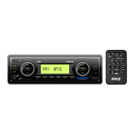
- Page 1 PLMR87WB OWNER’S MANUAL Mobile Audio System 7 MOD VOL + AS/PS MUTE BAND CH7/EQ DSP/0 VOL - C H 1 C H 2 C H 3 C H 4 C H 5 C H 6 DIR- DIR+ RESET www.pyleaudio.com...
-
Page 2: Table Of Contents
CONTENTS Automatic memory storing& Installation...........3 program scanning ......... 8 Take out screw before installation...3 Station storing........8 DIN Front-Mount (Method A) ....3 USB play operation ........8 Installing the unit........3 Supported MP3/WMA decoding modes Removing the unit .........4 ..............9 DIN Rear-Mount (Method B)....4 SD/MMC operation ........ -
Page 3: Installation
INSTALLATION Notes: having an opening as shown below: Choose the mounting location where the unit will not interfere with the 53mm normal driving function of the driver. Before finally installing the unit, connect 182mm the wiring temporarily and make sure it Installing the unit is all connected up properly and the Be sure you test all connections first, and... -
Page 4: Removing The Unit
INSTALLATION Spring Washer Hex Nut tabs behind the dashboard to secure the Metal Strap sleeve in place. Mounting Bolt Plain Washer Dashboard Tapping Screw Tabs Screwdriver Reconnect the cable to the vehicle Sleeve battery’s negative (-) terminal. Then 6. Reconnect the wire harness and the replace the outer trim ring. - Page 5 INSTALLATION Side View showing T, N Screw Screw Dashboard or Console Hook To fasten the unit to the factory radio mounting brackets. 1. Use a screwdriver to loose the hook’s screws on the front left and right sides of the unit and remove the hooks. 2.
-
Page 6: Wiring Connection
WIRING CONNECTION... -
Page 7: Operation
GENERAL OPERATION 6 7 8 7 MOD VOL + AS/PS MUTE BAND CH7/EQ DSP/0 VOL - C H 1 C H 2 C H 3 C H 4 C H 5 C H 6 DIR- DIR+ RESET 17 16 15 Repeatedly press DSP button(8) to show SWITCHING ON/OFF THE UNIT the information as below:... -
Page 8: Radio Operation
GENERAL OPERATION Press AS/PS button (6) for several Press MUTE button (9) to mute down the sound instantly. If any button is pressed seconds, the radio searches from the in the mute state, the mute state is current frequency and checks the released. -
Page 9: Supported Mp3/Wma Decoding Modes
GENERAL OPERATION SD/MMC OPERATION previous song or the following song. Track number shows on display. There is a SD/MMC interface (12) on the front panel of the unit. SELECTING DIRECTORY UP/DOWN When you insert a SD/MMC card in the Press DIR button (13) or DIR button SD/MMC interface, the unit will search... -
Page 10: Remote Control
REMOTE CONTROL HANDSET(OPTIONAL) FUNCTION KEY & CONTROL 1. POWER Power ON/OFF Button 2. MODE Mode Botton(S,T,U,7,For MP3/WMA Operation) 3. TUNE/SKIP Tune/SKIP Down Button(V,W,X,8 For MP3/WMA Operation) 4. 7/BND Band Select Button(When pressed shortly) 5. SCN Scanning Button(D,E,F,2 For MP3/WMA Operation) 6. -
Page 11: Specification
SPECIFICATION GENERAL Power Supply Requirements : DC 12 Volts, Negative Ground Chassis Dimensions : 178 (W) x 107 (D) x 50 (H) Tone Controls : ±10 dB Bass (at 100 Hz) : ±10 dB Treble (at 10 kHz) Maximum Output Power Version Y : 4x50 watts Current Drain... -
Page 12: Trouble Shooting
TROUBLE SHOOTING Before going through the checklist, check wiring connection. If any of the problems persist after checklist has been made, consult your nearest service dealer. Symptom Cause Solution The car ignition switch is power supply No power. not on. connected to the car accessory circuits, but the engine is not moving, switch the ignition key...