
Related Manuals for JETWAY V600DA


Summary of Contents for JETWAY V600DA
- Page 1 V600DA / V600DAP User's Manual AMD Socket 462 Processor Motherboard VIA KT600 + VIA 8237 Revision 3.0 P / N: G03 -V600DA...
-
Page 2: Table Of Contents
Trademarks Notice ..........................ii Safety Instructions ..........................ii Packing Item Checklist.......................... iv AMD Socket A Processor Thermal Solutions..................iv CHAPTER 1 INTRODUCTION OF V600DA/V600DAP MOTHERBOARD FEATURE OF MOTHERBOARD ..................1 SPECIFICATION........................2 PERFORMANCE LIST ......................3 LAYOUT DIAGRAM & JUMPER SETTING ..............4 CHAPTER 2 HARDWARE INSTALLATION PRE-HARDWARE INSTALLATION................. -
Page 3: Manual Revision History
OR TRANSLATED INTO ANY LANGUAGE IN ANY FORM OR BY ANY MEANS WITHOUT WRITTEN PERMISSION OF THE MANUFACTURER. THIS MANUAL CONTAINS ALL INFORMATION REQUIRED TO USE V600DA/ V600DAP MOTHER-BOARD AND WE DO ASSURE THIS MANUAL MEETS USER’S REQUIREMENT BUT WILL CHANGE, CORRECT ANY TIME WITHOUT NOTICE. MANUFACTURER PROVIDES THIS MANUAL “AS IS”... -
Page 4: Safety Instructions
or trademarks of NVIDIA Corporation in the United States and/or other countries. PS/2 and OS®/2 are registered trademarks of International Business Machines Corporation. PCMCIA and CardBus are registered trademarks of the Personal Computer Memory Card International Association. Windows® 98/2000/NT/XP are registered trademarks of Microsoft Corporation. -
Page 5: Amd Socket A Processor Thermal Solutions
CD for motherboard utilities Cable for USB Port 3/4 (Option) □ V600DA / V600DAP User’s Manual AMD Socket A Processor Thermal Solutions As processor technology pushes to faster speeds and higher performance with increasing operation clock, thermal management becomes increasingly crucial while building computer systems. -
Page 6: Chapter 1 Introduction Of V600Da/V600Dap Motherboard
Chapter 1 Introduction of V600DA / V600DAP Motherboard Thank you for purchasing the V600 series which provide extremely performance and meet future specification demand. V600 series motherboards are adopted with advanced technologies to deliver the extremely performance for socket A processors. -
Page 7: Specification
1-2 Specification Spec Description ∗ ATX form factor 4 layers PCB size: 30.5x21.0cm Design ∗ VIA KT600 North Bridge Chipset for V600DA/V600DAP Chipset ∗ VIA VT8237 South Bridge ∗ Support AMD Athlon 700MHz∼1.4GHz processor CPU Socket ∗ Support AMD Duron 600MHz∼1.4GHz processor ∗... -
Page 8: Performance List
1-3 Performance List The following performance data list is the testing result of some popular benchmark testing programs. These data are just referred by users, and there is no responsibility for different testing data values gotten by users (the different Hardware & Software configuration will result in different benchmark testing results.) Performance Test Report CPU:... -
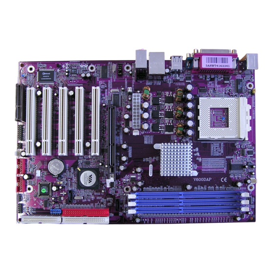
Page 9: Layout Diagram & Jumper Setting
1-4 Layout Diagram & Jumper Setting PRINT PS/2 Mouse LINE-IN PS/2 Keyboard LINE-OUT COM1 COM2 USB1 K/B Power ON Jumper (JP1) CPU Socket PS2 KB/Mouse Port CPU FAN DDR DIMM X3 PC99 Back Panel VIA KT600 Chip USB Port USB Port/ LAN Connector ATX Power Connector Audio Connector (CN1) -
Page 10: Expansion Sockets
Jumpers Jumper Name Description Page JP3, JP4 CPU Front Side Bus Frequency 2x2-pin Block JBAT CMOS RAM Clear 3-pin Block Keyboard Power On Enable/Disabled 3-pin Block CPU Ratio Select 2x5-pin Block Connectors Connector Name Description Page ATXPOW ATX Power Connector 20-pin Block P.13 PS/2 Mouse &... -
Page 11: Chapter 2 Hardware Installation
Chapter 2 Hardware installation 2-1 Pre-Hardware installation Before starting to use the computer with the motherboard installing the components on it, please make sure complete the following steps: To verify the settings of your motherboard To install the CPU To install the system memory To install the expansion cards To connect with ribbon cables, panel wires, and power supply To setup BIOS... - Page 12 CPU Ratio Selector (3) Keyboard Power On function Enabled/Disabled: JP1 When setting Enabled you can using keyboard by key in password to power on system. 1-2 closed K/B Power ON Disable 2-3 closed K/B Power ON Enabled (Default) Keyboard Power On Setting (4) CMOS RAM Clear (3-pin) : JBAT A battery must be used to retain the motherboard configurations in CMOS RAM.
-
Page 13: To Install The Cpu
2-3 To install the CPU 3-1 Glossary Chipset (or core logic) - two or more integrated circuits which control the interfaces between the system processor, RAM, I/O devises, and adapter cards. Processor socket - the socket used to mount the system processor on the motherboard. Slot (AGP, PCI, ISA, RAM DIMMs) - the slots used to mount adapter cards and system RAM. -
Page 14: About Amd Athlon Xp & Duron 462-Pin Cpu
2-3-2 About AMD Athlon XP & Duron 462-pin CPU This motherboard supports Socket-A (Socket-462) AMD Athlon XP /Duron processors. This motherboard Provides a ZIF Socket-A. The CPU that comes with the motherboard should have a cooling fan and heatsink attached to prevent overheating. If this is not the case, then purchase a correct cooling fan with heatsink before you turn on your system. -
Page 15: To Install The System Memory
2-4 To install the system memory This motherboard provides three 184-pin DUAL INLINE MEMORY MODULES (DIMM) sites for memory expansion available from minimum memory size of 64MB to maximum memory size of 3.0GB DDR SDRAM. Valid Memory Configurations Bank 184-Pin DIMM Total Memory Bank 0, 1 (DDR1) PC2100/PC2700/PC3200 DDR SDRAM... -
Page 16: To Install The Expansion Cards
2-5 To install the Expansion Cards Turn off your power when adding or removing expansion cards or other WARNING! system components. Failure to do so may cause severe damage to both your motherboard and expansion cards. 2-5-1 Procedure For Expansion Card Installation To read documentations or manuals for your expansion cards and make any necessary hardware or software settings for your expansion card such as jumpers. -
Page 17: Interrupt Request Table For This Motherboard
2-5-3 Interrupt Request Table For This Motherboard Interrupt requests are shared as shown the table below: INT A INT B INT C INT D PCI slot 1 Shared PCI slot 2 Shared ... -
Page 18: Connectors And Pin Headers
2-6 Connectors and pin headers 2-6-1 Connectors (1) Power Connector (20-pin block) : ATXPOW ATX Power Supply connector. This is a new defined 20-pins connector that usually comes with ATX case. The ATX Power Supply allows to use soft power on momentary switch that connect from the front panel switch to 2-pins Power On jumper pole on the motherboard. - Page 19 (7) Serial Port COM1, COM2 : COM1, COM2 COM1, COM2 are the 9-pin D-Subminiature mail connector. The On-board serial port can be disabled through BIOS SETUP. Please refer to Chapter 3 “INTEGRATED PERIPHERALS SETUP” section for more detail information. PS/2 Mouse PRINT USB1 LINE-IN...
-
Page 20: Pin Headers
IDE1 IDE2 Pin 1 Pin 1 • Two hard disks can be connected to each connector. The first HDD is referred to as the “Master” and the second HDD is referred to as the “Slave”. • For performance issues, we strongly suggest you don’t install a CD-ROM or DVD-ROM drive on the same IDE channel as a hard disk. - Page 21 (2) USB Port Headers (9-pin) : USB1, USB2 These headers are used for connecting the additional USB port plug. By attaching an option USB cable, your can be provided with two additional USB plugs affixed to the back panel. USB1 USB2 Pin 1 Pin 1...
- Page 22 JW _ FP SPEAK Pin 1 Pin 1 System Case Connections (9) Wake On-LAN Headers (3-pin) : WOL This connector connects to a LAN card with a WAKE ON-LAN output. This connector power up the system when a wake up signal is received through the LAN card.
- Page 23 (11) IR infrared module Headers (9-pin) : IR This connector supports the optional wireless transmitting and receiving infrared module. You must configure the setting through the BIOS setup to use the IR function. Pin 1 IR infrared module Headers (12) CD Audio-In Headers (4-pin) : CDIN1 CDIN1 is the connector for CD-Audio Input signal.
-
Page 24: Starting Up Your Computer
2-7 Starting up your computer 1. After all connection are ready, close your computer case cover. 2. Be sure all the switches are off, and check that the power supply input voltage is set to proper position, usually in-put voltage is 220V∼240V or 110V∼120V depending on your country’s voltage used. -
Page 25: Chapter 3 Introducing Bios Settings
Chapter 3 Introducing BIOS Settings The BIOS is a program located on a Flash Memory of the motherboard. Using this program as a bridge between motherboard and operating system. When the computer starting to work, the BIOS program gain control. The BIOS first operates an auto-diagnostic test called POST (power on self test) for all the necessary hardware, it detects the entire hardware device and configures the parameters of the hardware synchronization. -
Page 26: Getting Help
3-2 Getting Help Main Menu The on-line description of the highlighted setup function is displayed at the bottom of the screen. Status Page Setup Menu/Option Page Setup Menu Press F1 to pop up a small help window that describes the appropriate keys to use and the possible selections for the highlighted item. - Page 27 Standard CMOS Features Use this Menu for basic system configurations. Advanced BIOS Features Use this menu to set the Advanced Features available on your system. Advanced Chipset Features Use this menu to change the values in the chipset registers and optimize your system’s performance.
-
Page 28: Standard Cmos Features
3-4 Standard CMOS Features The items in Standard CMOS Setup Menu are divided into several categories. Each category includes no, one or more than one setup items. Use the arrow keys to highlight the item and then use the <PgUp> or <PgDn> keys to select the value you want in each item. CMOS Setup Utility –... -
Page 29: Advanced Bios Features
If the controller of HDD interface is CD-ROM, the selection shall be “None” Access Mode The settings are Auto Normal, Large, and LBA. number of cylinders Cylinder Head number of heads Precomp write precomp Landing Zone landing zone number of sectors Sector 3-5 Advanced BIOS Features CMOS Setup Utility –... - Page 30 Enabled Activates automatically when the system boots up causing a warning message to appear when anything attempts to access the boot sector of hard disk partition table. CPU L1 Cache The default value is Enabled. Enabled (default) Enable cache Disabled Disable cache Note: The internal cache is built in the processor.
- Page 31 Typematic Rate Setting Keystrokes repeat at a rate determined by the keyboard controller. When enabled, the typematic rate and typematic delay can be selected. The settings are: Enabled/Disabled. Typematic Rate (Chars/Sec) Sets the number of times a second to repeat a keystroke when you hold the key down. The settings are: 6, 8, 10, 12, 15, 20, 24, and 30.
-
Page 32: Advanced Chipset Features
3-6 Advanced Chiset Features The Advanced Chipset Features Setup option is used to change the values of the chipset registers. These registers control most of the system options in the computer. CMOS Setup Utility – Copyright(C) 1984-2003 Award Software Advanced Chipset Features >... -
Page 33: Dram Timing Settings
3-6-1 DRAM Timing Settings CMOS Setup Utility – Copyright(C) 1984-2003 Award Software DRAM Timing Settings Auto Configuration By SPD Item Help x RAS Active Time x RAS Precharge Time Menu Level >> x RAS to CAS Delay CAS Latency 2.5T Bank Interleave 4 Bank DRAM Command Rate... -
Page 34: Agp Timing Settings
3-6-2 AGP Timing Settings CMOS Setup Utility – Copyright(C) 1984-2003 Award Software AGP Timing Settings AGP Transfer Aperture Size Item Help AGP Mode Auto AGP Driving Control Auto Menu Level >> x AGP Driving Value AGP Fast Write Disabled AGP Master 1 WS Write Enabled AGP Master 1 WS Read Enabled... -
Page 35: Integrated Peripherals
3-7 Integrated Peripherals CMOS Setup Utility – Copyright(C) 1984-2003 Award Software Integrated Peripherals > OnChip IDE Function Press Enter Item Help > OnChip Device Function Press Enter > Onboard Super IO Function Press Enter Menu Level > Init Display First PCI Slot ↑↓→←... -
Page 36: Onchip Ide Function
3-7-1 OnChip IDE Function CMOS Setup Utility – Copyright(C) 1984-2003 Award Software OnChip IDE Function OnChip IDE Channel0 Enabled Item Help OnChip IDE Channel1 Enabled Primary Master Auto Primary Slave Auto Menu Level >> Secondary Master PIO Auto Secondary Slave PIO Auto Primary Master UDMA... -
Page 37: Onchip Device Function
3-7-2 OnChip Device Function CMOS Setup Utility – Copyright(C) 1984-2003 Award Software OnChip Device Function VIA LAN Function Enabled ← ( Item Help Only for V600DAP) VIA LAN Boot ROM Disabled AC97 Sound Device Auto Menu Level >> AC97 Modem Device Auto Game Port Address Midi Port Address... -
Page 38: Onchip Super Io Function
3-7-3 Onboard Super IO Function CMOS Setup Utility – Copyright(C) 1984-2003 Award Software Onboard Super IO Function Onboard FDD Controller Enabled Item Help Onboard Serial Port 1 3F8/IRQ4 Onboard Serial Port 2 2F8/IRQ3 Menu Level >> UART2 Mode Normal RxD, TxD Active Hi, Lo IR Duplex Mode Half... -
Page 39: Power Management Setup
SPP/EPP/ECP/ECP+EPP To operate the onboard parallel port as Standard Parallel Port only, choose “SPP.” To operate the onboard parallel port in the EPP modes simultaneously, choose “EPP.” By choosing “ECP”, the onboard parallel port will operate in ECP mode only. Choosing “ECP+EPP”... -
Page 40: Wake Up Events
Video Off Method This determines the manner in which the monitor is blanked. DPMS (default) Initial display power management signaling. Blank Screen This option only writes blanks to the video buffer. V/H SYNC+Blank This selection will cause the system to turn off the vertical and horizontal synchronization ports and write blanks to the video buffer. -
Page 41: 3-8-1.1 Irqs Activities
Wake-Up on RTC Alarm This function is for setting date and time for your computer to boot up. During Disabled, you cannot use this function. During Enabled, choose the Date and Time Alarm: Date(of month) Alarm You can choose which month the system will boot up. Set to 0, to boot every day. Time(hh:mm:ss) Alarm You can choose what hour, minute and second the system will boot up. -
Page 42: Pnp/Pci Configuration Setup
3-9 PnP/ PCI Configuration Setup This section describes configuring the PCI bus system. PCI, or Personal Computer Interconnect, is a system which allows I/O devices to operate at speeds nearing the speed the CPU itself uses when communicating with its own special components. This section covers some very technical items and it is strongly recommended that only experienced users should make any changes to the default settings. -
Page 43: Irq Resources
3-9-1 IRQ Resources CMOS Setup Utility – Copyright(C) 1984-2003 Award Software IRQ Resources IRQ3 assigned to PCI Device Item Help IRQ4 assigned to PCI Device IRQ5 assigned to PCI Device IRQ7 assigned to PCI Device Menu Level >> IRQ9 assigned to PCI Device IRQ10 assigned to PCI Device... -
Page 44: Miscellaneous Control
Current CPU Temperature/Current System Temp/Current FAN1, FAN2 Speed/Vcore/ Vdd/ 3.3V/+5V/+12V/-12V/VBAT(V)/5VSB(V) This will show the CPU/FAN/System voltage chart and FAN Speed. Detect CPUFAN in Post During Enabled, system will warn the user if CPU Fan is not functioning. Miscellaneous Control 3-11 This section is for setting CPU Frequency/Voltage Control. -
Page 45: Load Standard/Optimized Defaults
Load Standard/Optimized Defaults 3-12 Load Standard Defaults When you press <Enter> on this item, you get confirmation dialog box with a message similar to: Load Standard Defaults (Y/N)? N Pressing <Y> loads the BIOS default values for the most stable, minimal-performance system operations. -
Page 46: Chapter 4 Driver & Free Program Installation
Chapter 4 DRIVER & FREE PROGRAM INSTALLATION Check your package and there is A MAGIC INSTALL CD included. This CD consists of all DRIVERS you need and some free application programs and utility programs. In addition, this CD also include an auto detect software which can tell you which hardware is installed, and which DRIVERS needed so that your system can function properly. -
Page 47: Via 4In1 Install Via Service Pack 4 In 1 Driver
4-1 VIA 4IN1 Install VIA Service Pack 4 IN 1 Driver The path of the file is X:\VIA\DRIVER\SETUP.EXE IDE : VIA ATAPI VENDOR SUPPORT DRIVER IS USED TO FIXED COMPATIBILITY ISSUE FOR IDE DEVICES AGPVXD : VIA AGPVXD DRIVER IS TO BE INSTALLED, IF YOU ARE USING AN AGP VGA CARD, VIAGART.VXD WILL PROVIDE SERVICE ROUTINES TO YOUR VGA DRIVER AND INTERFACE DIRECTLY TO HARDWARE, PROVIDING FAST GRAPHIC ACCESS... - Page 48 Click NEXT to Install ATAPI Vender Click NEXT to choose enabled DMA Mode Support Driver Click NEXT to Install VIA AGP VXD Click NEXT to Install VIA IRQ Routing Driver Mini port Driver Click Finish to restart computer...
-
Page 49: Sound Install Alc Audio Codec Driver
SOUND install ALC AC97’ Codec Audio Driver 1. Click SOUND when MAGIC INSTALL 2. Then auto detect operation system language MENU appears edition, click OK, start to install DRIVER 3. Click Finish and Restart Windows 4. Click Start→Program→Avance Sound Manager→AvRack. Then AVRACK Windows appears 5. -
Page 50: Lan Install Via 10/100Mb Lan Controller Driver
7. 2/4/6 channel speaker configuration setting 8. 6 channel speaker place test Note: The path of the file For WIN98/NT4.0/WIN2K/XP is X:\CODEC\ALC\SETUP.EXE Note: In Win2K/WinME users have to click Control Panel\System\Device Manager\ DVD\CD-ROM drives to Enabled digital CD Audio for the CD-ROM Device when use the SPDIF-Out digital signal. -
Page 51: Pc-Health Winbond Hardware Doctor Monitoring Software
PC-HEALTH Winbond Hardware Doctor Monitoring Software The path of the file is X:\VIA\HEALTH-W\SETUP.EXE (Only support WINDOWS 95/98/98SE/ME) In Windows 95/98 Winbond Hardware Doctor Monitoring Software needs some system files to copy in Utility that’s why it needs install PC-HEALTH twice to complete setup. 1. -
Page 52: Magic Bios Install Bios Live Update Utility
4-5 MAGIC BIOS Install BIOS Live Update Utility Click Magic BIOS when Magic Install Click Next to install the Magic BIOS in MENU appears Destination Folder After finish Setup you will have a Magic Double click the Magic BIOS icon you will BIOS icon in your screen have this picture, choose from internet you can upgrade BIOS On-line... -
Page 53: Pc-Cillin Install Pc-Cillin2002 Anti-Virus Program
When choose From Local Driver to update 10. Choose the correct BIOS file to update BIOS BIOS, you must have the correct BIOS file in your Local Driver PC-CILLIN Install PC-CILLIN 2002 Anti-virus program 1. Click PC-CILLIN when MAGIC INSTALL 2. -
Page 54: Usb2.0 Install Via Usb2.0 Device Driver
5. Click INSTALL, Start to install the software 6. Setup Complete and click FINISH 7. After PC-CILLIN 2002 complete, Please 8. finish register process, we recommend select register your information and get LICENSE update item to download newest engine code KEY from TREND MICRO web site, enter and virus code your license key and click FINISH... -
Page 55: Sata Install Via Serial Ata Driver
3. Select Install USB Driver and Click NEXT 4. Select FINISH and Restart your Computer 5. Check device working properly in Device Manager The Path of the file is X:\VIA\VIAUSB20\SETUP.EXE SATA Install VIA Serial ATA 1. Click SATA when MAGIC INSTALL MENU 2. -
Page 56: How To Disable On-Board Sound
STEP 2. Copy utility program to your boot disc. You may copy from DRIVER CD X:\FLASH\AWDFLASH.EXE or download from our web site. STEP 3. Copy latest BIOS for V600DA/V600DAP from our web site to your boot disc. STEP 4. Insert your boot disc into A:, start the computer, type “Awdflash A:\ V600DAPAxxx.BIN /SN/PY/CC/R”...