Table of Contents
Troubleshooting

Related Manuals for HP Codemaster 100


Summary of Contents for HP Codemaster 100
- Page 1 User’s Guide Including: • HP M2475B CodeMaster 100 Portable Defibrillator/Monitor with 12-Lead ECG option • HP M2480B Battery Support System • HP M2478A DC Power Module • HP M2479A AC Power Module HP CodeMaster 100 Portable Defibrillator/Monitor...
-
Page 2: Responsibility Of The Manufacturer
Hewlett-Packard Company. Before using the HP CodeMaster 100 , the battery support system, or the power modules, read this guide and become thoroughly familiar with the contents. - Page 3 EMI frequency generation from electrosurgical equipment and close proximity transmitters may seriously degrade performance of the HP CodeMaster 100 . Hewlett-Packard assumes no liability for failures resulting from EMI between HP medical electronics and any radio frequency generating equipment at levels exceeding those established by applicable standards.
-
Page 4: Printing History
Notice Associated Documents Document Title HP Part Number HP M2475B CodeMaster 100 Portable M2475-97800 Defibrillator/Monitor Quick Reference Guide HP CodeMaster Series Defibrillator/Monitor M1722-94920 Pacing Application Note Understanding Pulse Oximetry M1722-93950 Concepts HP M2475B CodeMaster 100 Portable M2475-90905 Defibrillator/Monitor Service Manual... -
Page 5: Symbol Definitions
Symbol Definitions Symbol Definitions The following symbols appear on the HP CodeMaster 100 :... - Page 6 Symbol Definitions The following symbols appear on the HP M2480B battery support system. The following symbols appear on the HP M2478A DC power module. The following symbols appear on the HP M2479A AC power module:...
-
Page 7: Conventions
Conventions Conventions This manual uses the following conventions: Warning statements describe conditions or actions that can result in WARNING personal injury or loss of life. Caution statements describe conditions or actions that can result in damage to the CAUTION equipment or loss of data. Notes contain additional information on usage. -
Page 8: Preface
A direct current defibrillator applies a brief, high-energy pulse of electricity to the heart muscle (up to 360 joules). The HP CodeMaster 100 delivers this energy through multi-function defib electrodes or paddles applied to the patient’s chest. -
Page 9: Intended Use
When operating as a manual defibrillator, the HP CodeMaster 100 is suitable for use by personnel trained in advanced cardiac life support. In Shock Advisory Mode, the HP CodeMaster 100 is suitable for use by EMS personnel with basic life support training. - Page 10 • consciousness • presence of breathing • presence of detectable pulse In addition, the HP CodeMaster 100 should not be used in Shock Advisory Mode (where it functions like an AED) for: • children who weigh under 90 pounds • patients who have an implanted pacemaker...
-
Page 11: Noninvasive Pacing
Preface Noninvasive Pacing Indications The HP CodeMaster 100 provides non-invasive pacing that delivers an electrical stimulus to the heart, causing cardiac depolarization and myocardial contraction. The energy is delivered through multifunction defib electrodes placed on the chest. Non-invasive pacing, as a therapy, is indicated for use in patients with symptomatic bradycardia or asystole. -
Page 12: 12-Lead Electrocardiography
Preface 12-Lead Electrocardiography Indications The American Heart Association (AHA) and the National Heart Attack Alert Program (NHAAP) recommend prehospital 12-Lead ECG with computer analysis and transmission to the emergency department for patients with chest pain and possible Acute Myocardial Infarction (AMI). The prehospital 12-Lead ECG offers paramedics and emergency physicians significant advantages over the single lead ECG typically available in EMS. -
Page 13: Electromagnetic Compatibility
Preface Electromagnetic Compatibility Reducing Electromagnetic Interference xiii... -
Page 14: Restrictions For Use
Preface Restrictions for Use Immunity Level NOTE... -
Page 15: Telecom Regulatory Information
Telecom Regulatory Information Telecom Regulatory Information United States In compliance with the Federal Communications Commission (FCC), the following information is provided: • This equipment complies with Part 68 of the FCC rules. This unit bears a label which contains the FCC registration number and Ringer Equivalence Number. If requested, this information must be provided to the telephone company. -
Page 16: Canada
Telecom Regulatory Information Canada In compliance with the Industry Canada, the following information is provided: • NOTICE: The Industry Canada label identifies certified equipment. This certifica- tion means that the equipment meets telecommunications network protective Technical Requirements document(s). The department does not guarantee the equipment will operate to the user’s satisfaction. -
Page 17: United Kingdom
Telecom Regulatory Information United Kingdom In compliance with the Department of Trade and Industry, the following information is provided: Although this equipment can use either loop disconnect or DTMF signaling, only DTMF signaling is subject to regulatory requirements for correct operation. It is, therefore, strongly recommended that the equipment is set to use DTMF signaling for access to public or private emergency services. - Page 18 Telecom Regulatory Information xviii...
-
Page 19: Table Of Contents
Associated Documents iv Printing History iv Symbol Definitions v Conventions vii Preface viii Introduction viii About the HP Codemaster 100 viii Theory of Defibrillator Operation viii Intended Use ix Indications and Contraindications ix Defibrillation ix Defibrillation x Noninvasive Pacing xi... - Page 20 Connecting the Paddles or Multifunction Defib Electrodes and Patient Cables 2-3 Connecting Paddles or Multifunction Defib Electrodes 2-4 ECG Input Connector 2-5 Configuring the CodeMaster 100 and 12-Lead ECG Option 2-7 Configuring the CodeMaster 100 2-8 Restoring Factory Settings 2-9 Configuring the 12-Lead Option 2-13...
- Page 21 Keyboard Parameters 2-21 Setup Transmission 2-24 Setting Up the Telephone Directory 2-27 Setup Automated Operations 2-29 3 Defibrillating Defibrillating a Patient 3-1 1. Select Energy 3-1 2. Charge 3-3 Resetting the Selected Energy Level 3-4 3. Shock 3-4 Preparing the Defibrillator for the Next Use 3-5 Defibrillation with Alternate Paddle Sets or Multifunction Defib Electrodes 3-6 Performing Pediatric Defibrillation 3-6...
- Page 22 5-Wire Patient Cable/10-Wire Patient Cable 5-4 Preparing the Patient 5-5 ECG Monitoring Electrodes 5-7 Using Multifunction Defib Electrodes 5-7 Using Paddles 5-7 Monitoring a Patient the CodeMaster 100 5-8 Heart Rate Alarms 5-9 Recording 5-10 Recording/Printing ECG and Monitoring Data 5-10 Automatic Recordings 5-11...
- Page 23 Managing Stored ECGs 6-32 Printing the Log of ECGs Stored 6-33 Print the Configuration 6-33 Send Event Summaries 6-33 HP CodeMaster 100 and 12-Lead Option Interactions 6-34 7 Performing Synchronized Cardioversion Performing Cardioversion 7-1 Monitoring During Cardioversion 7-1 Using an External Monitor 7-1...
- Page 24 Pacer Operating Controls 8-2 Using the Pacer 8-2 Defibrillation During Pacing 8-7 9 SpO Monitoring Understanding Pulse Oximetry 9-1 What is SpO2? 9-2 How Does Pulse Oximetry Work? 9-2 SpO2 Operating Controls 9-3 Patient Monitor Using SpO2 9-3 Sensor Types 9-3 Using SpO2 9-4 Apply the Sensor to the Patient 9-4 Applying the Reusable Sensor 9-4...
- Page 25 External Power Module Indicators 11-4 Installing the External DC Power Module 11-5 Testing the External Power Module Installation 11-6 CodeMaster 100 External Power Indicators 11-7 Monitoring with External Power 11-8 Charging the Battery with an Auxiliary Power Module 11-8 Defibrillating with External Power 11-9...
- Page 26 Identifying Storage Problems 12-16 Identifying Transmission Problems 12-17 Sales 12-19 Medical Supplies 12-21 Service 12-21 13 Maintenance CodeMaster 100 13-1 Operation Checks 13-1 Every Shift 13-1 Every Day 13-2 Delivered Energy and Shock Button Functional Test 13-3 Electrode Adapter Cable Test 13-4...
- Page 27 Monitor 14-3 External Pacer 14-3 2 14-4 Measurement Range: 0 to 100%. 14-4 Thermal Array Recorder 14-5 Size and Weight of the CodeMaster 100 without the 12-Lead Option 14-5 Advisory Mode (Option C80) 14-6 12-Lead (Option C90) 14-7 Battery 14-9...
- Page 28 xxviii...
-
Page 29: Getting Acquainted
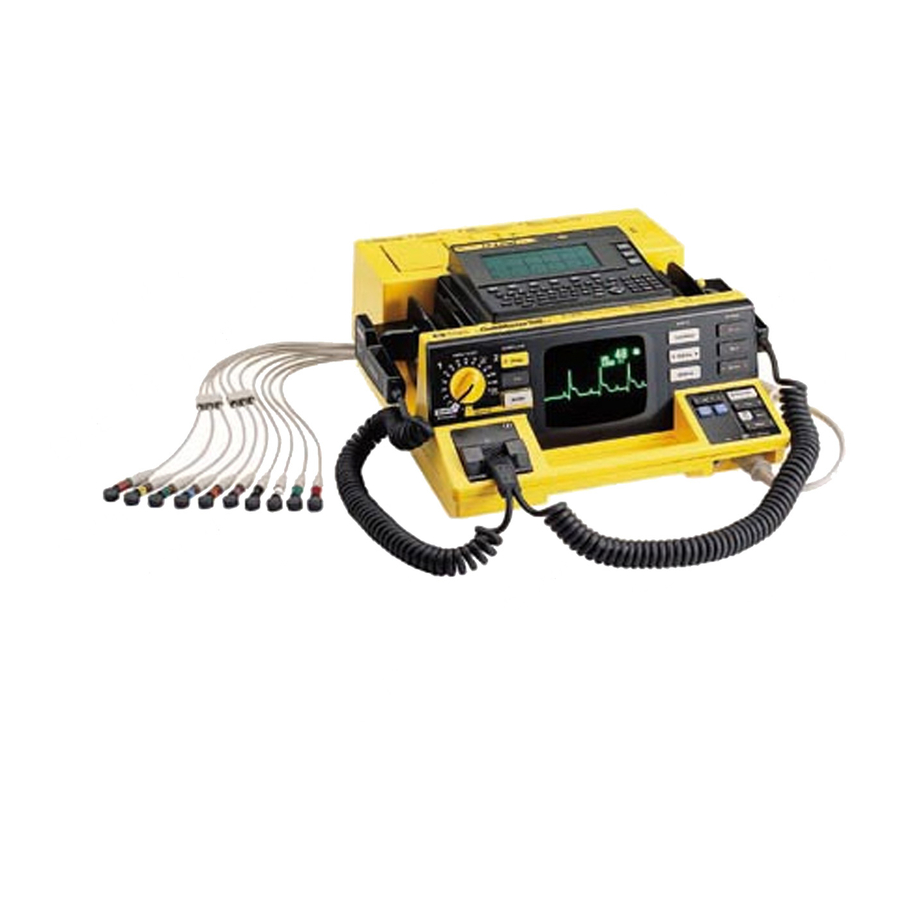
Getting Acquainted This user’s guide provides operational and basic maintenance instructions for safe use and proper care of the HP CodeMaster 100. It also details setup, configuration, and troubleshooting procedures. This section serves two purposes: to familiarize you with the major CodeMaster 100 features and to show their respective locations on the device. - Page 30 Figure 1-1 Quick-change battery Adult/Pediatric 12-Lead paddle Recorder Defibrillator/ Monitor CRT Adult/Pediatric paddle M2475-B0001 Paddles/electrodes cable connector The CodeMaster 100 Defibrillator/Monitor with 12-Lead ECG Option Overview (Top View)
- Page 31 Figure 1-2 M2475-B0002 Connector ECG Connector The CodeMaster 100 Defibrillator/Monitor with 12-Lead ECG Option Overview (Front View)
-
Page 32: Operating Controls And Indicators
This topic provides figures and tables which detail the controls and indicators on the HP CodeMaster 100. Defibrillator Operating Controls The defibrillating operating controls on the HP CodeMaster 100 include Energy Select, Charge, Sync, and Shock. See Figures 1-3 and 1-4. Figure 1-3... - Page 33 Operating Controls and Indicators Figure 1-4 Energy Select ENERGY SELECT DEFIBRILLATOR Control Charge Sync Monitor On Advisory On M2475-B0006 Defibrillator Operating Controls (2 of 2)
- Page 34 The Charge button charges the defibrillator to the energy level set on the Energy Select control. Charge buttons are located on the front panel of the CodeMaster 100 and on the apex paddle. Sync The Sync button changes the operating mode...
-
Page 35: Monitor Operating Controls
Operating Controls and Indicators Monitor Operating Controls This section details the operating controls on the HP CodeMaster 100 that enable you to monitor a patient. Refer to Figure 1-5. Refer to Chapter 5, “Monitoring” for more information about patient monitoring. - Page 36 Operating Controls and Indicators Control/Button Function Lead Select Selects an ECG source to monitor. ECG Size Changes the displayed ECG size. Controls heart rate alarms. HR Alarm Controls the volume of the QRS beeper. ECG Output connector Located on the right side of the unit - provides analog 1V/mV output for external monitoring...
-
Page 37: Recorder Operating Controls
Operating Controls and Indicators Recorder Operating Controls This section details the recorder operating controls associated with the recorder (printer) on the HP CodeMaster 100. Refer to Figure 1-6. Figure 1-6 RECORDER Record Mark Review M2475-B0005 Recorder Operating Controls Control/Button Function Record Starts and stops the recorder. - Page 38 This annotation can be configured to print on the ECG strip immediately when Mark is pressed or after a 6 second delay. Refer to Chapter 2, “Setup and Configuration” to configure the HP CodeMaster 100 for recording when Mark is pressed.
-
Page 39: Pacer Operating Controls
Operating Controls and Indicators Pacer Operating Controls This section details the pacer operating controls associated with pacing. Refer to Figure 1-7. Figure 1-7 Pacer On Rate Start Mode Stop Output SpO2 ECG Input M2475-B0005 Pacer Operating Controls 1-11... - Page 40 Operating Controls and Indicators Control/Button Function Pacer On Provides setup functionality. Rate Adjusts the pacer rate (ppm) higher or lower. Starts and stops pacing. Start/Stop Output Adjusts the pacer output current (mA) up or down. Mode Changes between fixed and demand pacing modes. Pacing does not start until you press Start/Stop.
-
Page 41: Spo2 Operating Controls
Operating Controls and Indicators Operating Controls This topic details the SpO operating controls associated with the SpO feature on the HP CodeMaster 100. Refer to Figure 1-8. Figure 1-8 On/Off Alarm SpO2 ECG Input Sp0 2 Connector M2475-B0005 Operating Controls... - Page 42 Operating Controls and Indicators Operating Controls Control/Button Function On/Off Starts and stops the pulse oximeter Controls SpO alarms Alarm Connector sensors and adapter cables plug into the input connector. Chapter 9, “SpO2 Monitoring” contains further information about using the pulse oximeter. 1-14...
-
Page 43: Advisory Mode Operating Controls (Optional)
Operating Controls and Indicators Advisory Mode Operating Controls (Optional) This section details the operating controls for the HP CodeMaster 100 in Advisory Mode. Figure 1-9 illustrates the placement of the controls. Figure 1-9 ENERGY SELECT DEFIBRILLATOR Charge Energy Select Sync... -
Page 44: 12-Lead Operating Controls
Operating Controls and Indicators 12-Lead Operating Controls This section provides an overview of the 12-Lead portion of the CodeMaster 100. Figure 1-10 shows the keypad and operator buttons that you use to setup, acquire, and transmit patient data. Refer to Chapter 6, “Using the 12- Lead Option”... - Page 45 Operating Controls and Indicators Figure 1-10 12-Lead Send Menu < > H " J ’ ’ Shift & Shift Filter Copy Stop M2475-B0004 12-Lead Keyboard and Display 1-10 1-17...
-
Page 46: Indicator Lights
Operating Controls and Indicators Indicator Lights The HP CodeMaster 100 contains several status lights that illuminate to indicate the device status. This topic provides details for each indicator. Refer to Figures 1-11 and 1-12. Table 1-1 lists audible indicators. Figure 1-11... - Page 47 Operating Controls and Indicators Figure 1-12 Battery capacity gauge M2475-B0007 Quick-change battery Battery Indicator Lights 1-12 Indicator Function Battery Capacity Gauge After you press the button below the indicator, the battery capacity gauge indicates the remaining battery charge. 1-19...
- Page 48 Operating Controls and Indicators Table 1-1 Audible Indicators Indicator Description It can be disabled in setup It can be disabled in setup CHECK BATTERY LOW BATTERY 1-20...
-
Page 49: Safety Considerations
Safety Considerations Safety Considerations The HP CodeMaster 100 stores high voltage energy and is capable of delivering up to 360 joules of DC energy to a 50 ohm impedance. To remove power from the instrument, you must turn the Energy Select control to Off. - Page 50 Never touch the bed, gurney, the patient, or any equipment connected to the patient during defibrillation. Keep the HP CodeMaster 100 and the immediate area clean and dry at all times to avoid creating potentially dangerous electrical paths. Never open the instrument case. Dangerous high voltages can be exposed.
-
Page 51: Battery Operation
Battery Operation Battery Operation The HP CodeMaster 100 operates from a nickel-cadmium battery (Figure 1- 13). This battery provides optimum performance and battery life when charged and maintained using the HP M2480B Battery Support System. Figure 1-13 HP M2476B/M2477B Battery 1-13 In addition to the standard M2476B 2.5 amp-hour battery, Hewlett-Packard... -
Page 52: Supported Battery Replacements
Battery Operation Supported Battery Replacements Replace the battery only with one of the batteries listed in Table 1-2. Table 1-2 Battery Specifications 360 Joules Approximate Battery Charge-Shock Monitoring Time Recharging Time Cycles Testing a Battery To test the remaining charge in the battery, press the button below the battery capacity gauge. - Page 53 Battery Operation When the LOW BATTERY message is displayed on the monitor, replace the CAUTION battery pack with a charged battery pack. From the time the LOW BATTERY message appears until the battery is fully depleted and the instrument shuts down, there is approximately thirty minutes of monitoring and five 360 joule charge-shock cycles.
- Page 54 Battery Operation 1-26...
-
Page 55: Setup And Configuration
This chapter provides steps for setting up and configuring the HP CodeMaster 100. Your HP CodeMaster 100 ships protected within a carry bag. For instructions on s how to attach the side-pouches and shoulder strap, refer to M3710A Carry Bag Instructions for Use (M2475-94000). -
Page 56: Inserting The Battery
Setting Up the CodeMaster 100 Inserting the Battery Before using the battery supplied with your HP CodeMaster 100, make sure it is fully charged and functional. Remove the battery from the defibrillator by pinching the latch and pulling the battery out and up. -
Page 57: Loading The Recorder Paper
Loading the Recorder Paper The HP CodeMaster 100 recorder uses 50mm wide, thermal recorder paper (HP 40457C/D). To load the paper, refer to “Changing the Recorder Paper” on page 13-7. -
Page 58: Connecting Paddles Or Multifunction Defib Electrodes
Setting Up the CodeMaster 100 Connecting Paddles or Multifunction Defib Electrodes To connect the paddles/electrode adapter cable to the defibrillator, perform the following steps: Slide the paddle connector lock on the paddles plug to the unlock position. To do this, push the lock towards the top of the connector. -
Page 59: Ecg Input Connector
Setting Up the CodeMaster 100 ECG Input Connector The HP patient cable supplied with this device, or an HP approved WARNING substitute patient cable, is an integral part of the defibrillator/monitor safety features. Using any other patient cable may compromise defibrillation protection as well as performance. - Page 60 Setting Up the CodeMaster 100 Figure 2-3 . . . Connecting a Patient Cable...
-
Page 61: Configuring The Codemaster 100 And 12-Lead Ecg Option
Configuring the CodeMaster 100 and 12-Lead ECG Option Configuring the CodeMaster 100 and 12-Lead ECG Option This section provides instructions for configuring the CodeMaster 100 and 12-Lead ECG option. To configure general items such as the date and time, as well as all defibrillating and monitoring settings, use the Setup Menus accessible through the front panel keys and front display. -
Page 62: Configuring The Codemaster 100
Configuring the CodeMaster 100 Configuring the CodeMaster 100 Perform the following steps to configure the CodeMaster 100. Depress Sync and HR Alarm while turning the Energy Select control from Off to Monitor On. A Setup/Diagnostic menu will appear with the following choices. -
Page 63: Restoring Factory Settings
This process restores factory settings on the defibrillator/monitor and not on the 12-Lead option. HP recommends that you not use the 12-Lead option to acquire, view, store, WARNING print or transmit when in Diagnostic Mode as the ECG may be lost and the... - Page 64 Configuring the CodeMaster 100 To set the time on the CodeMaster 100: Example Press Sync and HR Alarm at the same time while turning the Energy Select control from Off to Monitor On. Press ECG Size once to highlight SETUP MENU 1.
- Page 65 Configuring the CodeMaster 100 Table 2-1 and Table 2-2 show configurable parameters on the instrument. Default values are shown in boldface type. Table 2-1 Setup Menu 1 Settings Setting Choices Description English 120, 140, 160 40, 60, 90 SYNC 70 (ppm)
- Page 66 Configuring the CodeMaster 100 Table 2-2 Setup Menu 2 Settings Setting Choices Description Delay 6 S. Monitor 200, 200, 360 PADDLES 3 WIRE 60 HZ SWEEP If you use a 10-wire cable, the leads which may be monitored are dependent upon NOTE whether the defibrillator is configured to monitor a 3 or 5-wire patient cable.
-
Page 67: Configuring The 12-Lead Option
Configuring the 12-Lead Option Configuring the 12-Lead Option This topic provides procedures for configuring the 12-Lead option. Table 2-3 lists the selections available on the Configuration Menu. Table 2-3 12-Lead Configuration Menu Settings Menu Selection Function 2-13... -
Page 68: Navigating The Configuration Menus
Configuring the 12-Lead Option Navigating the Configuration Menus When you need to edit the 12-Lead configuration, use the following techniques: • To enter the 12-Lead configuration menu, press the Menu key on the keyboard. • To select from a menu, press to move the cursor down, or press to move the cursor up until the desired menu line is highlighted, then press F3 to display... -
Page 69: Using The 12-Lead Configuration Menu
Configuring the 12-Lead Option Using the 12-Lead Configuration Menu The 12-Lead option can be customized to meet your particular requirements. Using the Configuration Menu, you can choose the screens from which you can set the 12- Lead configuration. When you select Configure 12-Lead from the Main Menu, the Configuration Menu appears: Configuration Menu Setup ID Entry... -
Page 70: Setting Up Patient Information
Configuring the 12-Lead Option Setting Up Patient Information The Setup ID Entry screen allows you to choose the patient identification entries requested prior to recording an ECG. The following screen shows the patient identification entries available for configuration. Enter data for patient information. Use F3 to change the value of a field. -
Page 71: Setting Up 12-Lead Fields
Configuring the 12-Lead Option Setting Up 12-Lead Fields This screen allows you to choose the default formats that will be used when you power-on the system. Table 2-4 shows the available report formats. Use F3 to change a field. Table 2-4 Configurable Report Characteristics Parameter Choices... - Page 72 Configuring the 12-Lead Option Setup 12-Lead Settings Lead Format: Standard 12-Lead Report Format: Custom Rhythm Leads for- 3x4 1R: 3x4 3R, Manual 3: Phone Line: Tone Change Format Exit 2-18...
-
Page 73: Setting Up Filters
Configuring the 12-Lead Option Setting Up Filters From the Configuration Menu, select Setup ECG Filters. The 12-Lead option has been factory-configured with the filter settings which remove the most noise from the ECG. In addition to the default settings, 12-Lead offers a choice of several filter configurations. - Page 74 Configuring the 12-Lead Option • The Muscle Artifact filter will be enabled when the Filter key is pressed. It removes small-amplitude, high-frequency signals, characteristic of muscle tremor. When the front panel Filter key is on, the user-configured combination of the NOTE Artifact, 0.5 Hz Wander, and 40 Hz Noise filters is enabled and the Filter status message appears in the upper-right corner of the display.
-
Page 75: Setting Up Interpretation, Copy Count, Institution Label, And
Configuring the 12-Lead Option Setting Up Interpretation, Copy Count, Institution Label, and Keyboard Parameters Setup Miscellaneous Institution Label: Hewlett-Packard 12-Lead Interpretation: Standard Adult/Pediatric Copy Count: 2 Set Keyboard: lowercase 12-Lead location code: 00000 12-Lead ID: 0000 Erase Exit Changing the Institution Label The Institution name is printed and transmitted with all ECGs and is displayed at the top of the Main Menu. - Page 76 Configuring the 12-Lead Option Setting Interpretation Values Interpretation values determine which analysis is applied to an ECG report. The settings are: None Selecting None disables printing of all computer generated interpretation of the ECG. The waveform prints along with the following fields: Patient ID, Patient Name, Date and Time Measurements Selecting this setting provides an additional page containing...
- Page 77 Setting 12-Lead ID The 12-Lead ID code identifies the particular CodeMaster 100 unit that was used to acquire the ECG. The number prints at the bottom of the report. If set to zero (default), this field will be omitted from the printed report. This parameter can be any four digit numeric code.
-
Page 78: Setup Transmission
Setup Transmission This menu allows the configuration of both the internal and an external modem. Note that your CodeMaster 100 with the 12-Lead option is pre-configured using Hayes™-compatible settings. Hewlett-Packard recommends that you not change any default settings if you are using the internal modem or a Hayes-compatible external modem. - Page 79 These ECGs can also be autoforwarded to other destinations set up in the telephone directory. During the transmission process, the HP CodeMaster 100 will dial the Gateway phone number and transmit the ECG report along with the phone number of the final destination.
- Page 80 Configuring the 12-Lead Option In the Gateway Setup menu, there are two telephone fields: Primary and Alternate. The Primary field will be the first Gateway number dialed. If this number fails, the Alternate gateway number will be used. The Alternate field can be left blank if no alternate gateway number is available.
-
Page 81: Setting Up The Telephone Directory
Configuring the 12-Lead Option Setting Up the Telephone Directory To transmit ECGs, you must identify the receiving site, its telephone number and the type of transmission to send. You can enter the telephone numbers of up to 18 sites in the directory. To setup the telephone directory, perform the following steps: From the Configuration Menu, press F3 to select Setup Telephone Directory. - Page 82 Configuring the 12-Lead Option Enter the name, primary and alternate telephone numbers, receiver type, and speed. Press to move the cursor to a blank field line. Note that the modem ignores spaces and hyphens in the telephone number. Use the following special symbols to specify how you want the modem to dial the telephone number: •...
-
Page 83: Setup Automated Operations
Configuring the 12-Lead Option Table 2-3 Remote Sites, Transmission Types, and Recommended Speeds Receiver Type Recommended Speed Press F5 twice to exit the directory and return to the Configuration Menu. Setup Automated Operations This field allows you to configure the steps to send ECGs after acquisition. If you enter Yes into this field, the device will automatically go to the telephone directory immediately after an ECG is acquired. - Page 84 Configuring the 12-Lead Option 2-30...
-
Page 85: Defibrillating
Select Energy Charge Shock Note that for quick reference, these steps appear on both the outer case of the HP CodeMaster 100 and on the quick reference card attached to the carry bag. 1. Select Energy Turn the Energy Select control to the desired energy level. The defibrillator is now on. - Page 86 Defibrillating a Patient Do not spread electrolyte medium between the paddle electrodes on the WARNING chest. The patient can be burned if the medium forms a path between the electrodes. To avoid risk of electrical shock, do not allow the electrolyte medium to accumulate on your hands or on the paddle handles Use of a defibrillator in the presence of flammable agents or in an oxygen enriched atmosphere presents an explosion and fire hazard.
-
Page 87: Charge
Defibrillating a Patient Figure 3-1 Placing the Paddles for Defibrillation 2. Charge Press Charge on either the Apex paddle or on the instrument front panel. Call out “Clear!" to alert personnel to stand away from the patient. Wait for the charge done indicators: CHARGE DONE light and Charge Done tone. -
Page 88: Resetting The Selected Energy Level
Defibrillating a Patient Resetting the Selected Energy Level To increase or decrease the selected energy level after pressing the Charge button, perform the following steps. Move the Energy Select control to the new energy level. Wait for the charge done indicators. 3. -
Page 89: Preparing The Defibrillator For The Next Use
Perform the test described in “Delivered Energy and Shock Button Functional Test” on page 13-3. Turn the Energy Select control to Off and return the HP CodeMaster 100 to its storage location. Check that sufficient recorder paper and electrolyte medium or multifunction defib electrodes are available for the next use of the defibrillator. -
Page 90: Defibrillation With Alternate Paddle Sets Or Multifunction Defib Electrodes
Performing Pediatric Defibrillation The HP CodeMaster 100 paddle set comes with pediatric paddles. To use the pediatric paddle set, depress the release latch at the front of the standard external paddles while pulling forward on the adult paddle surface. This action will remove the adult paddle contact surface and expose the smaller pediatric contact surface. -
Page 91: Defibrillating Through Multifunction Defib Electrodes
Defibrillating a Patient Defibrillating through Multifunction Defib Electrodes The HP CodeMaster 100 has a multifunction electrode adapter cable (M2472A). This adapter cable allows defibrillation through multifunction defib electrodes. Defib electrodes have several advantages: • Allows "hands off" defibrillation. • Provides good quality monitoring. - Page 92 Defibrillating a Patient If the PADS OFF monitor message displays, check all patient connections. Select pads as the ECG source by pressing Lead Select until PADS appears on the display under the heart rate. Set the Energy Select control to desired energy. Press Charge.
-
Page 93: Defibrillating With Anterior/Posterior Paddles
Multifunction Defib Electrode Adapter Cable Defibrillating with Anterior/Posterior Paddles The HP M2495A Anterior/Posterior Paddles are similar to the anterior/anterior paddles, but provide a posterior electrode placed on the patient’s back. Refer to the packaging provided with the paddles for placement and usage guidelines. - Page 94 Defibrillating a Patient 3-10...
-
Page 95: Using Shock Advisory Mode (Optional)
This chapter details the use of Shock Advisory, an option that is available with the HP CodeMaster 100. In shock advisory mode, the HP CodeMaster 100 acts as a semi-automatic external defibrillator. When in shock advisory mode the HP CodeMaster 100 can: •... -
Page 96: Understanding Shock Advisory Operating Controls
Understanding Shock Advisory Operating Controls Understanding Shock Advisory Operating Controls The Shock Advisory mode operating controls on the HP CodeMaster 100 include the Advisory On selection on the Energy Select control and the Analyze button. See Figure 4-1. Figure 4-1... -
Page 97: Using Shock Advisory Mode
Using Shock Advisory Mode Using Shock Advisory Mode This section provides instructions for using the HP CodeMaster 100 in Shock Advisory mode. Make certain that you observe all safety precautions noted throughout this chapter. Do not use the HP CodeMaster 100 in Shock Advisory mode for: WARNING •children who weigh less than 90 pounds... -
Page 98: Verify Patient Condition
ECG. Pressing Analyze has no effect unless the Energy Select/Power On control is set to Advisory On. In advisory mode, you can use the HP CodeMaster 100 to: • analyze the patient’s cardiac rhythms by pressing Analyze to determine whether a defibrillation shock is needed •... - Page 99 Using Shock Advisory Mode In advisory mode, the HP CodeMaster 100 emits distinct sounds as described in Table 4-1. Table 4-1 Audible Indicators in Advisory Mode Indicator Description CHECK BATTERY...
- Page 100 To restore these functions, turn the Energy Select control to Monitor On or an energy setting. If you turn the Energy Select control to Monitor On or a specific energy setting, NOTE you place the HP CodeMaster 100 in manual mode and the advisory features are disabled.
-
Page 101: Apply Defib Electrode
Advisory mode. You must use the electrode adapter cable and multifunction defib electrodes when in advisory mode. The HP CodeMaster 100 will not analyze patient cardiac rhythms through external or internal paddle sets. The message ATTACH PADS CABLE displays if the defib electrode adapter cable is not connected. - Page 102 Using Shock Advisory Mode The unit will deliver defibrillator energy levels to a set of multifunction WARNING defib electrodes even if they are not attached to a patient. The message appears when there are no electrodes or there is poor PADS OFF electrodes-to-patient contact.
- Page 103 Using Shock Advisory Mode Figure 4-2 M2475-B0012 Connect Electrode Adapter Cable Attach the multifunction defib electrodes to the patient as instructed on the package. Use the Apex-Anterior electrode application shown on the package. This WARNING results in the modified Lead II configuration upon which the advisory algorithm was designed and tested.
-
Page 104: Press The Analyze Button
Incorrectly connecting the electrodes to the adapter cable can result in a failure to deliver energy to the patient. C. Press the Analyze Button When you place the HP CodeMaster 100 in Advisory mode, the monitor displays the following message: FOR ANALYSIS, 200J PRESS ANALYZE. - Page 105 Using Shock Advisory Mode Figure 4-3 ENERGY SELECT DEFIBRILLATOR Charge Energy Select Sync Analyze Analyze Monitor On Off (Standby) Advisory On Analyze Button When you press Analyze, the monitor displays: ANALYZING ECG nnnJ DO NOT TOUCH PATIENT SELECTED where nnn is the configured setting for the energy sequence. To perform accurate analysis, you must not touch or move the patient WARNING during this time.
- Page 106 Using Shock Advisory Mode The advisory algorithm needs 7 to 10 seconds of continuous, artifact free ECG data to decide whether the patient requires defibrillating. If excessive artifact due to CPR or patient transport is detected, the monitor displays the messages: ARTIFACT DETECTED DO NOT TOUCH PATIENT.
-
Page 107: Follow Prompts
Using Shock Advisory Mode If the electrode adapter cable is not connected to the HP CodeMaster 100, the NOTE message ATTACH PADS CABLE appears. The electrode adapter cable must be connected to start analysis. D. Follow Prompts Look frequently at the monitor and follow the displayed instructions. The monitor may display SHOCK ADVISED or NO SHOCK ADVISED. -
Page 108: No Shock Advised
Shock Buttons After the defibrillator charges, press the Shock buttons promptly. If the shock is not delivered within 30 seconds, the HP CodeMaster 100 disarms and the energy level remains the same for the next shock. You can disarm the defibrillator by switching the Energy Select control to the Off NOTE or Monitor On positions. -
Page 109: After Using The Defibrillator
Perform the test described in “Delivered Energy and Shock Button Functional Test” on page 13-3. Turn the Energy Select control to Off and return the HP CodeMaster 100 to its storage location. Check that sufficient recorder paper and electrolyte medium or multifunction defib electrodes are available for the next use of the defibrillator. -
Page 110: Printing The Advisory Event Summary Record
Printing the Advisory Event Summary Record Printing the Advisory Event Summary Record The advisory event summary record contains information about the resuscitation attempt while in advisory mode. When you print the summary, a header record and event summary directory print before the stored ECGs. ECGs related to events print after the directory record. - Page 111 Printing the Advisory Event Summary Record Figure 4-5 Advisory Event Summary Record To print the advisory event summary record, press Review. To stop printing the advisory event summary, press Review or Record. To review the advisory event summary after the instrument has been turned off or is turned to manual mode, turn the Energy Select control to Advisory On and press Review.
- Page 112 Printing the Advisory Event Summary Record The following table lists the events the directory shows. Table 4-2 Advisory Event Summary Record Information Event Description Notes Analyze Analyze Mark 4-18...
-
Page 113: Clearing Advisory Event Memory
The instrument retains event information after you turn the instrument off. Memory clears when the HP CodeMaster 100 is turned on, placed in Advisory Mode, and Analyze pressed or a new ECG strip is recorded (see Table 4-2, “Advisory Event Summary Record Information”). -
Page 114: Advisory Mode Default Settings
Advisory Mode Default Settings Advisory Mode Default Settings The HP CodeMaster 100 contains default settings for use in Advisory mode. Some of the settings can be altered using the Setup Menu. The following settings can be changed: • Default energy select sequence. You can choose to change the sequence from the factory default settings for a sequence of 200, 200, and 360 Joules, to a sequence of 200, 300, and 360 Joules. -
Page 115: Monitoring
CodeMaster 100, details of patient preparation that apply to the synchronized cardioversion, and pacing procedures. The HP CodeMaster 100 can be used for either short-term or long-term cardiac monitoring. A fully charged HP M2476B 2.5 amp-hour NiCd battery provides a minimum of two hours of continuous monitoring. A fully charged HP M2477B 4.0 amp-hour NiCd battery provides a minimum of three hours of... -
Page 116: Using Leads To Monitor
Using Leads to Monitor Using Leads to Monitor The monitoring functions of the HP CodeMaster 100 may be performed through any of the ECG sources shown in Table 5-1. The leads which may be monitored are dependent upon the ECG source and whether the defibrillator is configured to monitor a 3 or 5-wire patient cable. -
Page 117: Preparing The Leads For Monitoring
Using Leads to Monitor Preparing the Leads for Monitoring You can configure the HP CodeMaster 100 to use either a 3-wire, 5-wire, or 10-wire patient cable (with the 12-Lead option). Use the procedure as described in Table 2-2 on page 2-12 to set up the patient cable type (3-wire, 5- wire, 10-wire). -
Page 118: 5-Wire Patient Cable/10-Wire Patient Cable
Using Leads to Monitor 5-Wire Patient Cable/10-Wire Patient Cable Table 5-4 describes a typical lead-wire placement using the 5-wire or 10-wire patient cable. Table 5-5 shows how the individual leads are formed using the individual leadwires. Table 5-4 Electrode Placement Electrode Placement Table 5-5... -
Page 119: Preparing The Patient
Preparing the Patient Preparing the Patient Proper application and placement of electrodes is essential for quality ECG monitoring. Good contact between the electrode and the skin reduces the effects of motion artifact and signal interference. 1 If necessary, shave hair from the site to ensure good electrode to skin contact. - Page 120 Be careful to correctly align the cable plug when connecting the patient ECG leads cable to the HP CodeMaster 100. Correctly orient the cable plug key with the connector slot. If the ECG leads cable falls out or is incorrectly...
-
Page 121: Ecg Monitoring Electrodes
Do NOT use paddles to monitor the ECG during elective cardioversion WARNING procedures when the HP CodeMaster 100 is in synchronous (SYNC) mode. Refer to Chapter 7, ”Performing Synchronized Cardioversion”, for detailed information on performing elective cardioversion. -
Page 122: Monitoring A Patient The Codemaster 100
If you wish to reduce the ECG size, press ECG Size. The "gain bar" along the left side of the display represents 1 mV of signal amplitude. Autogain allows an initial quick set up when the HP CodeMaster 100 is turned NOTE on to automatically size the ECG based on the signal from the patient. -
Page 123: Heart Rate Alarms
Heart Rate Alarms Heart Rate Alarms The HP CodeMaster 100 provides three configurable pairs of upper and lower heart rate alarm limits. Each pair of heart rate alarm limits can be defined as described in Table 2-1 on page 2-11. While monitoring, you can select and enable any pair of pre-defined limits using HR Alarm. -
Page 124: Recording
Recording Recording Recording operating controls are detailed in “Recorder Operating Controls” on page 1-9. Recording/Printing ECG and Monitoring Data To print a record of the current ECG and of the monitor status, press Record. • The upper line of the ECG strip contains a periodic report of monitor parameters (Date, Time, Heart Rate, ECG Source, ECG Size, and Recorder mode). -
Page 125: Automatic Recordings
Recording Automatic Recordings As described in Table 2-2 on page 2-12, you can enable or disable any of the following automatic recordings: • Record on Mark • Record on Charge • Record on Shock • Record on Alarms The automatic recordings for both delayed and non-delayed recorder modes of operation are defined in Table 5-6. -
Page 126: Post Shock Data
Recording Post Shock Data As described in Table 2-2 on page 2-12, you can enable or disable the recording of post shock statistics. • If Post Shock Data is enabled, the defibrillator will record the shock deliv- ery statistics (Actual Delivered Energy, Patient Impedance, Peak Current). •... -
Page 127: Recorder Errors
Recording The Event Summary record is cleared each time the defibrillator is turned on NOTE and a new event occurs. This allows you to turn off the defibrillator and return later to review event information such as code statistics. Turn the defibrillator off between uses to ensure that Event Summary records are patient specific. -
Page 128: External Monitoring
External Monitoring Cables 1000:1 Voltage Divider Cable Connector Type HP Part No. The ECG output is also compatible with the interface to the HP Viridia NOTE Information Center and other HP central stations. Do not use the ECG output to synchronize another defibrillator. (The ECG-In NOTE to ECG-Out delay is 35 milliseconds.) -
Page 129: Using The 12-Lead Option
Introduction The 12-Lead option adds12-Lead electrocardiograph capabilities to the HP CodeMaster 100. It enables you to view, acquire, store, print, and transmit 12-Lead ECGs. You can configure this feature to provide an interpretation of the ECG to further aid in patient diagnosis. The 12-Lead option includes: •... -
Page 130: 12-Lead Keyboard And Display
12-Lead Keyboard and Display 12-Lead Keyboard and Display This section discusses the 12-Lead keyboard and provides detailed descriptions of all the function keys. Refer to Figure 6-1 for an illustration of the 12-Lead keyboard. - Page 131 12-Lead Keyboard and Display Figure 6-1 12-Lead Send Menu < > H " J ’ ’ Shift Shift & Filter Copy Stop M2475-B0004 12-Lead Keyboard and Front Panel...
- Page 132 12-Lead Keyboard and Display Table 6-1 12-Lead Keyboard Description Enter...
- Page 133 12-Lead Keyboard and Display Figure 6-2 Characters by Language...
-
Page 134: Patient And Operational Safety Notes
Patient and Operational Safety Notes Patient and Operational Safety Notes The HP CodeMaster 100 with the 12-Lead option isolates all connections to the patient from electrical ground. This reduces the possibility of hazardous currents passing from the device through the patient’s heart to ground. To ensure the patient’s safety and your own, observe the following reminders:... - Page 135 Patient and Operational Safety Notes The connection of an external modem or other telecommunications WARNING equipment may increase leakage currents beyond levels that are acceptable in a patient care environment. Always request that local safety personnel verify that multiple connected equipment comply with local requlatory standards before putting such equipment into service.
-
Page 136: Acquiring A 12-Lead Ecg
Acquiring a 12-Lead ECG Acquiring a 12-Lead ECG This section describes how to: • prepare the patient for an ECG • check the signal quality of the patient leads • enter patient ID and printed report information • record an ECG •... -
Page 137: To Acquire A 12-Lead Ecg
Acquiring a 12-Lead ECG To Acquire a 12-Lead ECG: If your HP CodeMaster 100 with 12-Lead is already configured, you can acquire an ECG by performing the following steps: 1 Connect the 12-Lead ECG cable to the patient. 2 Turn the Energy Select control to Monitor On. -
Page 138: Preparing The Patient
Acquiring a 12-Lead ECG Preparing the Patient For electrode placement information, refer to Figure 6-3. Figure 6-3 V4/C4 V5/C5 V1/C1 V6/C6 V2/C2 V3/C3 LA/L RA/R RL/N LL/F Lead Position V1/C1 Fourth intercostal space, at right sternal margin. V2/C2 Fourth intercostal space, at left sternal margin. V3/C3 Midway between V2 and V4. - Page 139 Acquiring a 12-Lead ECG For tips on proper ECG technique, see the quick reference card included with this product located in the carry bag front/top panel. Proper patient preparation and electrode placement are the most important elements NOTE in producing a high quality ECG trace. The patient should be supine when acquiring an ECG.
-
Page 140: Checking Signal Quality
Acquiring a 12-Lead ECG Table 6-2 Leads Off Labels Designator Meaning (AHA/IEC) Checking Signal Quality You can produce better ECGs by previewing the lead traces on the upper display before you acquire and print the ECG. By observing the traces and adjusting the leads accordingly, you can obtain the best possible ECG report. - Page 141 Acquiring a 12-Lead ECG Table 6-3 Lead Groups Group Leads Displayed Group 1 I, II, III Group 2 aVR, aVL, aVF Group 3 V1, V2, V3 Group 4 V4, V5, V6 Group 5 user configurable • To select which three leads to display on the screen, press the key, or the Space bar, to display the next lead group, or press the key to display...
-
Page 142: Entering Patient Id
Acquiring a 12-Lead ECG Entering Patient ID Entering patient ID information is not required to record an ECG. Note that for 12-Lead, some ID fields affect the interpretation of ECGs. To enter patient identification, perform the following steps (these steps assume all ID fields are enabled). -
Page 143: Reviewing And Changing Patient Id
Acquiring a 12-Lead ECG To change or erase data you have entered, press F1 Erase or use the Backspace key to delete the character to the left of the cursor. You can stop entering patient ID information at any time by pressing F5 (or Stop). Reviewing and Changing Patient ID To review and change the current patient ID information: 1 Press the ID key. - Page 144 Acquiring a 12-Lead ECG Table 6-4 Patient ID Fields Char.# Prompt Comments Entry (max) Change Units Change Change Change Units 6-16...
- Page 145 Acquiring a 12-Lead ECG To obtain high fidelity ECG tracings suitable for manual interpretation of the ST NOTE segment, use the 0.05 Hz or 0.15 Hz bandwidth filter selections. The 0.5 Hz baseline wander filter should not be used for manual interpretation of the ST segment. 6-17...
-
Page 146: Using Hp Aci-Tipi
ECG information. If you have configured HP ACI-TIPI as your interpretation option, when you press the 12-Lead key, the system displays the HP ACI-TIPI Data Entry screen as follows:... -
Page 147: Using Hp Tpi
HP TPI. The system acquires the ECG and prints a report with the HP TPI probability. If the patient does not meet the HP TPI criteria, the HP CodeMaster 100 will NOTE print the standard interpretation report, in place of the HP TPI report. For HP TPI criteria, refer to the HP Predictive Instruments Physician’s Guide. -
Page 148: Making Additional Printed Copies Of The Ecg Reports
Select the report type through the Setup Miscellaneous selection on the Configuration Menu. The reports that are available include: • 12-Lead ECG • 12-Lead ECG with HP ACI-TIPI • 12-Lead ECG with HP TPI • 12-Lead ECG with Measurements only •... -
Page 149: Changing The Layout And Content Of The Printed Reports
Setting Up the Printed Report Changing the Layout and Content of the Printed Reports The default format is set through the Configuration Menu. You can change the format and size (gain) through the ECG main screen. To change the report lead format: 1 Press Stop. - Page 150 Setting Up the Printed Report Figure 6-4 The ECG Report 6-22...
- Page 151 Setting Up the Printed Report Table 6-5 Report Annotations Description 6-23...
-
Page 152: Basic Measurements
Setting Up the Printed Report Basic Measurements The basic measurements table gives standard interval and duration measurements in milliseconds, and limb lead axis measurements in degrees. These are representative values for the dominant beat pattern in the ECG. Table 6-6 Basic Measurements Item Description... -
Page 153: Calibration Signals
Setting Up the Printed Report Calibration Signals The following table shows how the height of the calibration pulse indicates ECG sensitivity. Table 6-7 Calibration Signals Calibration ECG Size (mm/mV) Pulse V-leads Display Label Limb Leads 12-Lead V1 - V6 Report Examples The following figures illustrate ECG report formats with standard adult interpretation. - Page 154 Setting Up the Printed Report Figure 6-5 A Standard 3x4 ECG (3x4) 6-26...
- Page 155 Setting Up the Printed Report Figure 6-6 3x4 ECG with One Rhythm Strip (3x4, 1R) 6-27...
- Page 156 Setting Up the Printed Report Figure 6-7 An Auto 3x4 ECG with Three Rhythm Strips (3x4, 3R) 6-28...
-
Page 157: Using The 12-Lead Main Menu
Hewlett-Packard CodeMaster 100 12-Lead M2475 English © 1989, 1998 Hewlett-Packard Co. The system displays a message requesting that you attach the 12-Lead patient cable: Attach the HP 12-Lead ECG cable to take a 12-Lead Pulse Format Size Line 6-29... - Page 158 Using the 12-Lead Main Menu After you attach the cable, the system then displays the ECG home screen as follows: Pulse Format Size Line Press the Menu key on the 12-Lead keyboard. The system displays the Main Menu. From the Main Menu you can perform several functions. This section describes how to use each entry on the Main Menu.
-
Page 159: Sending Ecgs
One or more Stored ECGs can be "Sent" at a time. This is useful for sending ECGs to an HP TraceMaster ECG Management System for long term archival. Stored ECGs appear in this screen. The most recent ECG will appear at the top of the ECG list. -
Page 160: Managing Stored Ecgs
Using the 12-Lead Main Menu Managing Stored ECGs In this screen, one or more Stored ECGs can be managed at a time. Once selected, ECGs can be Deleted, Printed, or Edited. To print or edit a stored ECG: Highlight the desired ECG by using the Arrow button on the keypad. Once the ECG is highlighted, choose the soft key function that you want for managing the ECG. -
Page 161: Printing The Log Of Ecgs Stored
Using the 12-Lead Main Menu Printing the Log of ECGs Stored A list of all Stored ECGs can be printed on the printer. The printed ECG Log report includes the date, time, ID, Patient Name, and ECG report format. Print the Configuration When you select this entry, the system will print the current configuration. -
Page 162: Hp Codemaster 100 And 12-Lead Option Interactions
This section describes the interactions that occur between the HP CodeMaster 100 and the 12-Lead option. • If the HP CodeMaster 100 is reset or a shock is delivered while the 12-Lead option is attempting to acquire or store an ECG, 12-Lead operation is sus- pended and the ECG will be lost (with no recovery). -
Page 163: Performing Synchronized Cardioversion
CodeMaster 100 defibrillator and external monitor combination will deliver a synchronized shock within 60 ms of the peak of the R-wave. (See the HP M2475B CodeMaster 100 Portable Defibrillator/Monitor Service Manual for test procedure.) Use a 1 mV QRS complex with a QRS width of 40 ms. - Page 164 External ECG monitor When the patient is already connected to bedside monitoring equipment, there is an external monitoring cable which plugs into the ECG Output jack of the bedside monitor and connects to the HP CodeMaster 100 ECG Input for monitoring. To use an external monitor, perform the following steps: Select Lead I or Lead II on the HP CodeMaster 100.
-
Page 165: Using Paddles For Performing Synchronized Cardioversion
Turn the Energy Select control to Monitor On. Select the desired ECG lead by pressing Lead Select. Press Sync once to place the HP CodeMaster 100 in Sync mode. The message SYNC appears on the display. If you select paddles as the ECG source, the message USE LEADS will appear WARNING on the display. -
Page 166: Applying The Paddles
Performing Cardioversion Applying the Paddles Prepare the paddles by performing the following steps: Remove the paddles from their holders by grasping the handles and lifting straight up. Holding both paddles in one hand, apply electrolyte medium to both paddle electrode surfaces. To avoid the risk of electrical shock or burns, do not allow electrolyte WARNING medium to accumulate on your hands, the paddle handles, or the paddle... -
Page 167: Resetting The Selected Energy Level
Performing Cardioversion Wait for the Charge Done indicators. If you must disarm the charged defibrillator (if counter shock is not needed), turn the NOTE Energy Select control to Monitor On. Any stored energy will be discharged internally and the available energy on the display will return to 0. Resetting the Selected Energy Level To increase or decrease the selected energy level after Charge has been pressed, move the Energy Select control to the new energy level, and wait for the Charge... -
Page 168: Using Multifunction Defib Electrodes For Performing Synchronized Cardioversion
If the PADS OFF monitor message is displayed, check all patient connections. Select pads as the ECG source by pressing Lead Select. Press Sync once to place the HP CodeMaster 100 in Sync mode. The message SYNC will appear on the display. -
Page 169: Resetting The Selected Energy Level
•Adjust the placement of the multifunction defib electrodes to improve ECG R-wave quality. Press Charge on the front panel of the HP CodeMaster 100. Wait for the Charge Done indicators. If you must disarm the charged defibrillator (if counter shock is not needed), turn the NOTE Energy Select control to Monitor On. -
Page 170: After Using The Defibrillator
Perform the test described in “Delivered Energy and Shock Button Functional Test” on page 13-3. Turn the Energy Select control to Off and return the HP CodeMaster 100 to its storage location. Check that sufficient recorder paper and electrolyte medium or multifunction defib electrodes are available for the next use of the defibrillator. -
Page 171: Pacing
Pacing is required when the heart’s own conduction system slows dangerously. The HP CodeMaster 100 with the pacer can perform external transcutaneous pacing. The pacer provides demand (synchronous) and fixed (asynchronous) pacing modes. -
Page 172: Pacer Operating Controls
Attach the ECG monitoring electrodes as instructed in “Preparing the Leads for Monitoring” on page 5-3. Attach the patient cable to the ECG Input connector of the HP CodeMaster 100. Attach the patient cable leads to the ECG monitoring electrodes. - Page 173 Using the Pacer Attach the multifunction defib electrodes to the electrode adapter cable. The electrodes are correctly connected when the locking ring is twisted, locking the ears of the connector to the adapter cable. Turn the Energy Select control to the Monitor On position. •If the message NO PADDLES is displayed, check that the pads adapter cable con- nector is properly seated and latched.
- Page 174 Using the Pacer Demand Mode Pacing When in demand mode, the pacer will only deliver pacer pulses when the patient’s heart rate is lower than the selected pacer rate. Fixed Mode Pacing When in fixed mode, the pacer will deliver pacer pulses at the selected pacer rate.
- Page 175 Using the Pacer 15 To set the lowest possible output level to capture, decrease the current by decre- ments of 5 mA by pressing Output. NOTE If the monitoring ECG lead falls off while pacing in demand mode, the pacer will stop delivering pulses and the messages PACER STOP and LEADS OFF will appear.
- Page 176 Using the Pacer HR meters and HR alarms function during pacing, but they can be WARNING unreliable. The HR meter attempts to count QRS activity in both demand and fixed pacing modes. Observe the patient closely while pacing. Do not rely on heart rate alarms or the indicated heart rate as a measure of the patient’s perfusion status.
-
Page 177: Defibrillation During Pacing
Using the Pacer Defibrillation During Pacing If the patient must be defibrillated during pacing, perform the following steps. Set the desired energy level with the Energy Select control. Press Charge. The defibrillator will automatically turn off the pacer and start charging. - Page 178 Using the Pacer...
-
Page 179: Spo 2 Monitoring
Monitoring This chapter explains how to use the pulse oximeter feature of the HP CodeMaster 100. monitoring gives information on both cardiac and respiratory systems, and details of oxygen transportation in the body. It is widely used because it is non-invasive, continuous, easily applied and painless. -
Page 180: What Is Spo2
Understanding Pulse Oximetry What is SpO A blood-oxygen saturation reading indicates the percentage of hemoglobin molecules in the arterial blood which are saturated with oxygen. The reading is referred to as SpO . Readings vary from 0 to 100%. Normal readings in a healthy adult, however, range from 94% to 100%. -
Page 181: Spo2 Operating Controls
The patient must have at least a minimum pulse. The light emitter and the photodetector must be opposite each other. Operating Controls The SpO operating controls on the HP CodeMaster 100 SpO Operating Controls are detailed in “SpO2 Operating Controls” on page 1-13 Patient Monitor Using SpO... -
Page 182: Using Spo2
4 Apply the sensor to the identified location. 5 Connect the sensor to the monitor. To connect sensors from other manu- facturers, use the HP M1900B Connector Cable. Apply the Sensor to the Patient Hewlett-Packard supports the use of many sensors. Use the Sensor Guide to find the sensor which is best for your case. - Page 183 Patient Monitor Using SpO2 Figure 9-2 Applying the HP M1190A Reusable Sensor When non-HP SpO sensors are used, application must be consistent with the CAUTION manufacturer’s own guidelines. Prolonged, continuous monitoring may increase the risk of undesirable WARNING changes in skin characteristics, such as irritation, reddening, blistering or pressure necrosis, particularly on neonates and on patients with impaired perfusion and varying or immature skin morphology.
-
Page 184: Troubleshooting Sensor Application
Patient Monitor Using SpO2 Troubleshooting Sensor Application Failure to apply the sensor properly may cause incorrect measurement of arterial oxygen saturation. Do not use a damaged sensor or one with exposed electrical circuits. Patient Movement Make sure that the application site chosen does not move excessively, which may adversely affect the performance of the sensor. -
Page 185: Circulation At Application Site
When you have applied the sensor to the patient, plug the disposable and semi-disposable sensors into the connector cable and plug this cable into the socket on the lower right of the HP CodeMaster 100. Plug the HP M1190A sensor directly into the SpO socket of the HP CodeMaster 100. -
Page 186: Start Monitoring
Patient Monitor Using SpO2 Figure 9-3 MONITOR RECORDER Lead Select Record ECG Size Mark HR Alarm Review ECG Input Sp0 2 Input M2475-B0013 Connecting the SpO Sensor To avoid damaging the pins on the cable connector, do not force the SpO CAUTION connector into the ECG input socket. -
Page 187: Spo 2 Readings
The pulse rate is derived from the pulse oximeter. It should correlate closely with the patient’s heart rate. Figure 9-4 LEAD I I SPO2 PR 72 CodeMaster 100 Display with SpO Reading... -
Page 188: Spo 2 Alarms
Alarms Alarms Activating SpO Alarms There are three preset high/low SpO alarm limits: 100/90, 100/85 and 100/80. Press SpO alarm repeatedly to cycle through the alarm options and the no- alarm option. Stop when you see the alarm you would like to choose and after three seconds that alarm will take effect. -
Page 189: Transmitting Data From The 12-Lead Option
Summaries using the 12-Lead option of the HP CodeMaster 100. You can transmit using a landline or cellular phone with data link. The HP CodeMaster 100 supports data transmission from either an internal modem with an RJ11C connector (in US, UK, and Canada only) or an external modem via the RS-232 port. -
Page 190: Receiving Devices
• HP PageWriter 300pi/200i/200 cardiograph (M1770A, M1771A) equipped with storage and transmission option #A05 The CodeMaster 100 with the 12-Lead option can transmit the Event Summary to an event summary host. Transmitting to an HP ECG Manager System HP ECG Manager running on a PC acts as a gateway or receiving station which receives, prints, stores, and forwards 12-Lead ECGs. -
Page 191: Using Landline Communications
(regular phone jack) using either the internal modem or a Hayes-compatible external modem. Note that the RJ11C cable running from the CodeMaster 100 that attaches to the phone jack is a standard phone cable and not provided with the HP CodeMaster 100. - Page 192 Using Landline Communications Table 10-2 lists the direct communications capabilities via the RS 232 cable. HP recommends that you replace the serial cable on a regular basis based on used rate or at any time communications problems arise through the RS232 port, especially for units used outside of North America and the UK.
- Page 193 (M1765A) or Event Summary Host Example 2 Fax Machine Internal Modem HP TraceMaster RJ11C ECG Management Landline Connection System (M1730B) CodeMaster 100 with 12-Lead Option Example 3 HP PageWriter XLi Cardiograph (M1700A) Example 4 Standard Landline Connection (Internal Modem) 10-2 10-2 10-5...
- Page 194 Phone System Personal Computer running ECG Manager Example 1 (M1765A) or Event Summary Host Example 2 Landline Connection Fax Machine with External Modem CodeMaster 100 RS232 Port with 12-Lead Option HP TraceMaster ECG Management External RJ11C System (M1730B) Modem Example 3...
-
Page 195: Using Cellular Communications
Using Cellular Communications Using Cellular Communications Transmitting from the CodeMaster 100 with the 12-Lead option using a portable cellular phone has several advantages: 10-3 • can be used in EMS vehicles or outdoors • can be used when there is no convenient access to a phone jack Table 10-3 lists the cellular communications capabilities. - Page 196 Using Cellular Communications Figure 10-4 Transmit Receiving Site Cellular CodeMaster 100 Internal Modem with 12-Lead Option RJ11C Personal Computer running ECG Manager (M1765A) or Event Summary Host Cellular Cellular Data Interface Bag Phone Adapter (3 watt) (RJ11C Adapter) Standard Cellular Connection (Internal Modem)
- Page 197 Using Cellular Communications Figure 10-5 Transmit Receiving Site CodeMaster 100 with 12-Lead Option Cellular External Modem Personal Computer running ECG Manager (M1765A) or Event Sum- Cellular Cellular mary Host Data Interface Phone Adapter (3 watt) (RJ11C Adapter) Standard Cellular Connection (External Modem)
-
Page 198: Transmitting A 12-Lead Ecg
Transmitting a 12-Lead ECG Transmitting a 12-Lead ECG To transmit an ECG: Connect the cellular or landline connection cable to the modem. Select the ECGs to send. Press the Send key or select Send ECGs from the Main Menu. The Send ECG Display appears: Send ECGs (2 ECGs Stored) Screen 1 of 1... - Page 199 Transmitting a 12-Lead ECG Choose the transmission destination for the ECG from the phone directory using the arrow keys. Use the F4 key to move through the different directory pages. Press F2 or Send to transmit the ECG. The system displays a message indicating successful transmission and then returns to the home display.
-
Page 200: Transmitting An Event Summary
The Event Summary Telephone Directory screen appears. Press F2 or Send to transmit the event summary. The HP CodeMaster 100 transmits the event summary and indicates that it is executing the dialing sequence. The system then confirms the number it is dial- ing and that the sequence is being sent. - Page 201 Transmitting an Event Summary If the system does not transmit the event summary successfully, refer to the sec- tion “Identifying Transmission Problems” on page 12-17. Press the STOP key to halt the transmission process. NOTE For configuration information, refer to Chapter 2, ”Setup and Configuration”. 10-13...
- Page 202 Transmitting an Event Summary 10-14...
-
Page 203: Using Auxiliary Power
Using Auxiliary Power This section provides instructions for using auxiliary power sources with the HP CodeMaster 100 The AC Power Module Using the AC Power Module To use the AC power module: Battery technology used in this device still requires maintenance. The WARNING power module will not cycle/recondition batteries. -
Page 204: Indicators
Figure 11-1 11-1 Charging Indicator The charging indicator appears when the battery is installed in the HP CodeMaster 100 and the battery is being charged. Power Indicator The power indicator lights up when power is supplied to the AC Power Module. -
Page 205: Using The Dc External Power Module
Using the DC External Power Module Using the DC External Power Module The HP M2478A external power module is a 12-Volt DC power source for the HP CodeMaster 100. This module is designed specifically for emergency vehicles with 12 Volt electrical systems. With this module, your vehicle’s 12 Volt system can power the HP CodeMaster 100, saving the defibrillator/monitor battery for remote use. -
Page 206: External Power Module Indicators
Using the DC External Power Module External Power Module Indicators Figure 11-2 External Power Module Indicators 11-2 11-4... -
Page 207: Installing The External Dc Power Module
Using the DC External Power Module Installing the External DC Power Module You must be a qualified mechanic or electrician to install the power module. If the cable provided for input to the External Power Module is not long enough, make sure that you use 14 gauge or larger wire to extend the cable. -
Page 208: Testing The External Power Module Installation
Verify that the power indicator on the external power module and the external power indicator on the HP CodeMaster 100 both appear. Install a battery in the HP CodeMaster 100 and verify that the charging indicator appears on the External Power Module. -
Page 209: Codemaster 100 External Power Indicators
CodeMaster 100 External Power Indicators CodeMaster 100 External Power Indicators This section discusses the external power indicators on the HP CodeMaster 100 (see Figure 11-4). Figure 11-4 11-4 11-7... -
Page 210: Monitoring With External Power
Monitoring with External Power Monitoring with External Power Charging the Battery with an Auxiliary Power Module If the battery is not already charged and it is at operating temperature, it will charge whenever you plug the external power module into the defibrillator. The charging indicator on the external power module appears when the battery is charging. -
Page 211: Defibrillating With External Power
Defibrillating with External Power CAUTION Defibrillating with External Power NOTE 11-9... -
Page 212: Performing Operational Checks
Performing Operational Checks Performing Operational Checks 11-10... -
Page 213: Troubleshooting
CodeMaster 100, the pacer, SpO2, advisory, the external power module and the 12-Lead option. Refer to the following table for messages that relate to the CodeMaster 100 display and actions to take to correct them. Table 12-1... - Page 214 CodeMaster 100 Table 12-2 Defibrillator Messages (Continued) Message Cause Possible Solutions USE LEADS Sync Sync PADDLES PAD- LEAD I, II DLES PAD- DLES LEAD I, II PADDLES PAD- DLES PAD- LEAD I, II DLES PAD- DLES Energy Select MAXIMUM BATTERY...
-
Page 215: If The Defibrillator Does Not Charge
3 If the instrument remains unable to charge, turn the Energy Select con- trol to Off and use a backup defibrillator. 4 Press Review to print an event summary and keep any ECG strips from the defibrillator for later evaluation. 5 Alert HP service personnel. 12-3... -
Page 216: If The Defibrillator Does Not Deliver A Shock
Monitor On or Off position and use a back-up defibrillator. 6 Press Review to print an event summary and keep any ECG strips from the defibrillator for later evaluation. 7 Contact HP service personnel as soon as possible. 12-4... -
Page 217: Troubleshooting The Pacer
CodeMaster 100 Troubleshooting the Pacer Table 12-3 Pacer Messages Message Cause Possible Solutions PACER FAILURE PACER FAILURE PACER OUTPUT LOW STOP PACER NO PADS PADS OFF ATTACH Charge PADS Start/Stop 12-5... -
Page 218: Troubleshooting Spo2
CodeMaster 100 Troubleshooting SpO Table 12-4 Messages Message Cause Possible Solutions SPO2 FAILURE On/Off SPO2 SENSOR FAIL SPO2 CABLE OFF SPO2 NOISY SIGNAL SPO2 LIGHT INTERF 12-6... - Page 219 CodeMaster 100 Table 12-4 Messages Message Cause Possible Solutions SPO2 LOW SIG- perfusion read- ing is high or erratic 12-7...
-
Page 220: Troubleshooting The Advisory Mode
CodeMaster 100 Troubleshooting the Advisory Mode Table 12-5 Advisory Mode Messages Message Cause Possible Solutions ATTACH PADS CABLE FOR ANALYSIS, ATTACH PADS ARTIFACT DETECTED;DO NOT TOUCH PATIENT PADS OFF 12-8... -
Page 221: Troubleshooting The External Power Module (M2478A Or M2479A)
CodeMaster 100 Troubleshooting the External Power Module (M2478A or M2479A) Table 12-6 External Power Module Problems Problem Cause Possible Solutions 12-9... -
Page 222: Replacing The External Power Module Fuse
Replace the M2478A External Power Module fuse with a 10A Fast Blow fuse, HP 2110-0051. The M2479A External Power Module has a 5A Fast Blow fuse (HP 2110-0709) located under the power cord strain relief on the back of the module. -
Page 223: Performing Diagnostics
CodeMaster 100 Performing Diagnostics The following procedure allows functional inspection of the CodeMaster 100 portable defibrillator/monitor. 1 Turn the Energy Select control to the Monitor On position. The moni- tor trace will appear within ten seconds. 2 Press Lead Select until Lead I is displayed and verify that the message LEADS OFF appears, indicating that one or more leadwires are not connected. - Page 224 14 Turn the Energy Select control to Off. The defibrillator is ready for use if it passes the above checklist. A more extensive test of defibrillator/monitor functionality can be performed using the diagnostic service mode described in the HP M2475B CodeMaster 100 Portable Defibrillator/Monitor Service Manual. 12-12...
-
Page 225: The 12-Lead Option
The 12-Lead Option The 12-Lead Option If you have problems with an ECG, there are several things you may check before calling for service. This chapter tells how to solve basic ECG problems. Checking ECG Technique Many problems in taking an ECG may be related to electrode application. •... -
Page 226: Identifying Ecg Problems
The 12-Lead Option Identifying ECG Problems The following table shows symptoms and solutions to problems that can occur when recording an ECG. Table 12-7 ECG Problems and Solutions Problem Cause Possible Solutions Filter Filter Filter 12-14... -
Page 227: Identifying Recorder Problems
The 12-Lead Option Table 12-7 ECG Problems and Solutions (Continued) Problem Cause Possible Solutions Identifying Recorder Problems The following table shows symptoms and solutions to problems that can occur when the recorder will not start. Table 12-8 Recorder Problems and Solutions Problem Cause Possible Solutions... -
Page 228: Sampling Characteristics Of The 12-Lead Option
QRS amplitude. This effect is more pronounced with narrower signals, more commonly found in some pediatric electrocardiograms and in pacemaker pulses. The CodeMaster 100 with 12-Lead option minimizes this effect by: • using an integrating-type A/D converter • sampling all leadwires simultaneously •... -
Page 229: Identifying Transmission Problems
The 12-Lead Option Identifying Transmission Problems The following table shows symptoms and solutions to problems that can occur when transmitting an ECG. Table 12-10 Transmission Problems and Solutions Message Likely Cause Possible Solutions 12-17... - Page 230 The 12-Lead Option Table 12-10 Transmission Problems and Solutions (Continued) Message Likely Cause Possible Solutions 12-18...
-
Page 231: Sales
Sales Table 12-10 Transmission Problems and Solutions (Continued) Message Likely Cause Possible Solutions Sales For the HP sales office nearest to you, please refer to your local phone book or call your HP regional office: 12-19... - Page 232 Sales United States of America: Latin America: Medical Distribution Europe/Middle East/Africa: Canada: Asia Pacific Headquarters: Marketing Center Europe: 12-20...
-
Page 233: Medical Supplies
• In the U.S. only - call 1-800-225-0230 • Worldwide - visit our Medical Supplies website at: www.hp.com/go/medsupplies Service For telephone assistance, call the Response Center nearest to you, or visit our website at: www.hp.com/mpgcsd/. United States (800) 548-8833 Canada East (800) 361-9790... - Page 234 Service 12-22...
-
Page 235: Maintenance
Maintenance CodeMaster 100 Operation Checks These checks are intended to briefly verify the proper operation of the HP CodeMaster 100. Regularly perform a test routine incorporating the following checks along with visual inspection of all cables, paddles, and controls. Every Shift Perform the following checks every shift: Make sure that a battery is charging in the battery support system. -
Page 236: Every Day
CodeMaster 100 Every Day Inspect the battery in the HP CodeMaster 100 for visible signs of wear. Turn on the HP CodeMaster 100. If the instrument displays the LOW BATTERY message, replace the battery with a charged battery. Visually check the patient cables, paddles, cables, and pads adapter cables for wear, insulation nicks, and other damage. -
Page 237: Delivered Energy And Shock Button Functional Test
CodeMaster 100 Delivered Energy and Shock Button Functional Test To check the HP CodeMaster 100 with the paddles, perform the following steps: The HP CodeMaster 100 is designed to protect against delivering a shock NOTE when only one switch on the paddle set is pushed. -
Page 238: Electrode Adapter Cable Test
Electrode Adapter Cable Test To check the electrode adapter cable, perform the following steps: 1 Connect the HP M1781A test load to the electrode adapter cable. 2 Turn Energy Select to 100 joules. 3 Press Charge. Wait for the Charge Done indicators. -
Page 239: Quick Pacer Functionality Test
10 Disconnect the test load (M1781A) from the electrode adapter cable. Quick Pacer Functionality Test 1 Connect the electrode adapter cable to the defibrillator and the HP M1781A test load to the adapter cable. Turn the defibrillator on by turning the Energy Select switch to the Monitor On position. -
Page 240: Every Week
Every Three Months Perform the following checks every three months. Have the cable set tested for electrical continuity every three months. Perform a battery capacity test using the HP M2480B battery support system. See the HP M2475B CodeMaster 100 Portable Defibrillator/Monitor Service... -
Page 241: Maintaining The Defibrillator
Changing the Recorder Paper 13-1 3 Place a new roll of recorder paper (HP 40457C/D) in the recorder so that the paper unrolls from the top of the roll and the grid faces down as it comes out of the recorder. -
Page 242: Cleaning The Recorder Printhead
CodeMaster 100 7 Turn on the defibrillator and press Record to verify the paper is loaded properly. Cleaning the Recorder Printhead If the ECG strip has light or varying density printing, clean the printhead to remove any possible buildup of paper residue. -
Page 243: Cleaning Exterior Surfaces
CodeMaster 100 Cleaning Exterior Surfaces The HP CodeMaster 100 and accessories (except the ECG cable and carry bag) are chemically resistant to common hospital cleaning solutions and non-caustic detergents. The following list includes some approved cleaning solutions: • 90% Isopropyl alcohol (except adapters and patient cable) •... -
Page 244: Cleaning The Electrodes And Cables
Cleaning the Carry Bag (M3710A) Remove all contents from the side pouches, including the shorting bar (HP part number M3710-80030) which is stored in a small pocket inside the left pouch. Machine wash the carry bag in cold water with a mild detergent. Do not use bleach or wring. -
Page 245: Cleaning Exterior Surfaces On The Ac And Dc Power Modules
It is recommended that you charge batteries at room temperature (10-30°C). Be sure to alternate batteries between the HP CodeMaster 100 and the battery support system. Install a freshly charged battery pack in the HP CodeMaster 100 whenever the unit displays the warning message LOW BATTERY. -
Page 246: Achieving Optimal Battery Life
You will get the best battery performance if you remove the battery from the HP CodeMaster 100 as soon as you see LOW BATTERY on the display. The defibrillator displays this message just after you turn it on. Charge the battery completely before replacing it in the HP CodeMaster 100 portable defibrillator/monitor. -
Page 247: New Batteries
CodeMaster 100 A new HP M2477B 4.0 amp-hour battery will provide 75 360-joule NOTE charge-shock cycles or a minimum of 3 hours of monitoring time. Replace the battery when it fails to provide the minimum3 hours of monitoring time or 10 minutes of Low Battery warning time (starting from a fully charged battery). -
Page 248: Charging The Battery
CodeMaster 100 Charging the Battery Insert battery into the HP M2480B battery support system charging bay. The CHARGING indicator appears, to indicate that the battery is charging. The battery is fully charged when the READY indicator appears. A fully discharged HP M2476B 2.5 amp-hour battery takes approximately 2 hours to charge (a fully discharged HP M2477B 4.0 amp-hour battery takes... -
Page 249: Battery Capacity Test
CodeMaster 100 Battery Capacity Test Perform a battery capacity test every 90 days or when the START indicator ) flashes after you insert the battery pack into the battery support system for charging. 1 Insert the battery into charging bay. The... -
Page 250: Supplies
CodeMaster 100 Supplies This section provides part numbers for supplies. Battery 2.5 amp-hour battery M2476B 4.0 amp-hour battery M2477B Battery support system M2480B External Power Module DC external power module M2478A AC external power module M2479A Patient Cables Trunk cable 3-wire/12-pin - AAMI... -
Page 251: Battery Support System Power Cords
Switzerland 8120-2296 South Africa 8120-4600 Paddles Anterior/anterior paddle set (black) - PCI (transport) M2471A a. Meets CodeMaster 100 defibrillator/monitor specifications for water resistance. Defib Electrodes Multifunction adhesive electrode pads, adult, AAMI M3501A Multifunction adhesive electrode pads, adult, IEC M3502A Multifunction adhesive electrode pads, pediatric, IEC... -
Page 252: Monitoring Electrodes
CodeMaster 100 Monitoring Electrodes Adult snap electrodes M2202A Paper Recorder paper 40457C/D Cases Carry case for 12-Lead option M3710A 13-18... -
Page 253: Specifications
Specifications Defibrillator/Monitor Waveform: Damped sinusoidal (Lown). Output Energy (Delivered): 2, 3, 5, 7, 10, 20, 30, 50, 70, 100, 150, 200, 300, and 360 joules. Charge Control: Push-button on apex paddle and on front panel. Charge Time: Less than 5 seconds to 360 joules with a fully charged battery installed. -
Page 254: Equipment Classification
Defibrillator/Monitor Equipment stored in a car or ambulance under severe climate conditions will NOTE function until equipment reaches (adjusts to) operating environment listed above. Equipment Classification: • internally powered • degree of protection against ingress of liquids: IPX4, defibrillator pads and paddles dry connected. -
Page 255: Monitor
Defibrillator/Monitor Monitor Inputs: ECG may be viewed through paddles or patient cable. Lead I, II, III, or PADDLES selectable. Additional leads (aVR, aVF, aVL, V Leads) and PADS are available. Monitor and recorder indicate selected ECG source. Lead Fault: LEADS OFF message and dashed baseline appear on monitor if a lead becomes disconnected. -
Page 256: Spo
Defibrillator/Monitor Measurement Range: 0 to 100%. Accuracy with HP M1190A sensor: 1 standard deviation, 65-100%: ±2.5%, resolution: 1%. Averaging: 8 beats. alarm limits — range: 100/90, 100/85, 100/80. alarm delay: ten seconds after value drops below the low alarm setting. -
Page 257: Thermal Array Recorder
Frequency Response: -CodeMaster 100 without the 12-Lead option: 0.5 to 40 Hz -CodeMaster 100 with the 12-Lead option: 0.05 to 150 Hz selectable. Size and Weight of the CodeMaster 100 without the 12-Lead Option Defibrillator dimensions: 6.25 in H by 13.75 in W by 15.125 in D (15.9 cm H by 34.9 cm W by 38.4 cm D). -
Page 258: Advisory Mode (Option C80)
Defibrillator/Monitor Advisory Mode (Option C80) Analysis time: Seven to ten seconds. Output Energy (Delivered): Available protocol 200J, 200J, 360J and 200J, 300J, 360J. Analysis Control: Push-button on front panel. Charge Time: Less than 5 seconds to 360 joules with battery present. Armed Indicators: Charge done tone and available energy indicated on display. -
Page 259: 12-Lead (Option C90)
Storage: Capacity: 30 ECGs Type: 2 MB of non-removable flash memory Transmission of 12-Lead ECGs to HP ECG Manager (PC-Based Receiving Station Software): -Internal cellular/landline modem with RJ11C connector (US, Canada, UK only) -RS232 Port for external modem. - Page 260 Defibrillator/Monitor Reports: Full 12-Lead ECG report: 12-Lead ECG printed in 3X4 format with configurable rhythm strips. Size and Weight: Dimensions: 7.25 in H by 13.75 in W by 15.13 in D (18.5 cm H by 34.9 cm W by 38.4 cm D). Weight: 23.5lb (10.65 kg).
-
Page 261: Battery
Defibrillator/Monitor Battery HP M2476B 2.5 amp-hour battery Type: Rechargeable nickel-cadmium battery, 2.5 Ah, 12 V nominal. Capacity: M2475B Standard: 2500 mAH; 2.5 hours ECG monitoring or 50 full-energy discharges or 1.75 hours combined ECG and SpO2 monitoring while pacing. M2475B with the 12-Lead Option: 2500 mAH; 2.0 hours ECG monitoring or 50 full-energy discharges or 1.5 hours combined ECG and SpO2 monitoring while... -
Page 262: Hp M2480B Battery Support System
HP M2480B Battery Support System Battery storage: Range of -30 to 50°C. Should not be stored above 35°C for extended periods of time. HP M2480B Battery Support System Charging Specifications Charging capacity: Two batteries. Charge time: Typically 2 to 3 hours. -
Page 263: Hp M2478A Dc External Power Module
Instrument operation output: 12 V DC, 1.0 A, 12 W; 7 A, 85 W maximum. Charge time: With defibrillator/monitor turned to Off/Standby: typically four hours—HP M2476B 2.5 Ah Battery, typically six hours—HP M2477B 4.0 Ah Battery. Recommended charging temperature: 5° C to 35° C. -
Page 264: Hp M2479A Ac External Power Module
HP M2479A AC External Power Module HP M2479A AC External Power Module For use only with CodeMaster 100 Defibrillator/Monitor. 14-12... - Page 265 Index capacity test, 13-6, 13-11, 13-15 Numerics charging, 13-14 12-Lead option, configuration menu, 2-13 disposal, 13-13 12-Lead report, formats, 2-17 maintenance, 13-11, 13-15 14482A external monitoring cable, 5-14 monitoring time, 5-1 1625A patient cable, 5-2 operating time, 13-13 3-wire patient cable, 5-3 operation, 1-23 3x4 Auto report, 6-26 part numbers, 13-16...
- Page 266 Index pacer, 1-11 identifying, 12-14, 12-15 recorder, 1-9 intermittent waveform, 12-15 conventions, manual, vii jittery waveform, 12-15 copy count, setting, 2-23 muscle artifact, 12-14 Copy key, 6-4 respiratory interference, 12-14 copying Auto ECGs, 6-20 tremor, 12-14 CRT alerts, 1-20, 2-11, 4-5 ECG size custom ID fields, 6-16 adjusting, 5-8...
- Page 267 Index M1749B multifunction adhesive pads, 5-7, 13-17 M1749C multifunction adhesive pads, 5-7, 13-17 hands off defibrillation, 3-7 M1749D multifunction adhesive pads, 5-7, 13-17 heart rate alarms M1781A test load, 13-4, 13-5 defining limits, 2-11 M1782A external monitoring cable, 5-14 using, 5-9 M1783A external monitoring cable, 5-14 HR alarm M1900B connector cable, 9-4...
- Page 268 Index notch filter, 2-12 selecting as ECG source, 3-8 using for synchronized cardioversion, 7-6 pads adapter cable opening recorder door, 13-7 testing, 13-4 operation checks, 13-1 to 13-6 using for monitoring, 5-2 PADS OFF output button , 3-8, 8-3, 12-5 using, 8-4 part numbers, supplies, 13-16 oxidation...
- Page 269 Index adjusting, 5-8 setup mode, 2-9 quick pacer functionality test, 13-5 setup/diagnostic menu, 2-9 shift checks, 13-1 shock buttons defibrillating with, during pacing, 8-7 rate button using, 8-3 defibrillating with, using external adhesive pads, 3-8 READY indicator, 13-14 defibrillating with, using paddles, 3-4 receiving devices, 10-2 disarming defibrillator, 1-21 recharging time of battery, 1-24...
- Page 270 Index performing, 3-5, 4-15, 7-1 to 7-8 using paddles, 7-3 using pads, 7-6 SYSTEM FAILURE , 12-1 telephone directory, 2-13, 2-27 temperature specifications, 14-1 TEST 100J PASSED , 13-4, 13-5 testing battery capacity, 13-15 every three months, 13-6 pacer functionality, 13-5 pads adapter cable, 13-4 time, 2-10, 2-11 tones, 1-20, 4-5...