Table of Contents
Advertisement
This document is printed on chlorine free (ECF) paper with soy ink.
PA
011519
20000608-74800
本资料由OKXIA视听皮带资源库www.okxia.cn提供
CONTENTS
BLOCK & LEVEL DIAGRAM
CIRCUIT BOARDS
POWERED MIXER
SERVICE MANUAL
................................................ 3/5
............................................................ 6
......................................... 10
....................................................... 18/23
1.45K-479
EMX660
.................................... 7
............... 11
............................ 12
.............................. 15
................................. 17
............... 28
HAMAMATSU, JAPAN
Printed in Japan 2000.06
1
Advertisement
Table of Contents

Related Manuals for Yamaha EMX 660


Summary of Contents for Yamaha EMX 660
- Page 1 EMX660 POWERED MIXER SERVICE MANUAL 本资料由OKXIA视听皮带资源库www.okxia.cn提供 CONTENTS SPECIFICATIONS ..........3/5 DIMENSIONS ............6 PANEL LAYOUT ........7 BLOCK & LEVEL DIAGRAM ......... 10 CIRCUIT BOARD LAYOUT ....11 DISASSEMBLY PROCEDURE ......12 LSI PIN DESCRIPTION ......15 IC BLOCK DIAGRAM .........
- Page 2 IMPOR TANT NOTICE This manual has been provided for the use of authorized Yamaha Retailers and their service personnel. It has been assumed that basic service procedures inherent to the industry, and more specifically Yamaha Products, are already known and under- stood by the users, and have therefore not been restated.
-
Page 3: Specifications
EMX660 SPECIFICATIONS General specifications 300 W + 300 W/4ohms @0.5% THD at 1 kHz (POWER AMP OUT 1, 2) Maximum output power 215 W + 215 W/8ohms @0.5% THD at 1 kHz (POWER AMP OUT 1, 2) 600 W/8ohms @0.5% THD at 1 kHz (BRIDGE) 20 Hz~20 kHz +1 dB, –3 dB @1 W output into 8ohms (POWER AMP OUT) Frequency response 20 Hz~20 kHz +1 dB, –3 dB @+4 dB output into 10 kohms (MAIN OUT, MONITOR OUT, EFFECT SEND) - Page 4 EMX660 Input specifications Input level Actual load Nominal Connector Input connectors impedance impedance type Max. before Nominal level Sensitivity cliping 50~600ohms –62 dB (0.616 mV) –50 dB (2.45 mV) –20 dB (77.5 mV) CH INPUT (Lo-Z) Mics 3 kohms XLR-3-31 type (CH1~4) 600ohms Lines –32 dB (19.5 mV) –20 dB (77.5 mV)
- Page 5 EMX660...
- Page 6 EMX660 DIMENSIONS W:497 (67.5) 45.5 45.5 57.5 D:275 Units: mm...
-
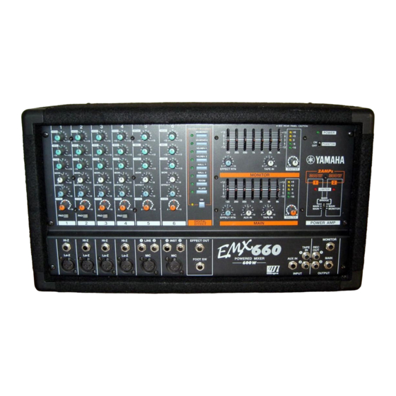
Page 7: Panel Layout
EMX660 PANEL LAYOUT Control panel Channel section HIGH Equalizer controls (HIGH, MID, LOW) Monitor controls (MONI) –15 Effect control (EFFECT) Level control (LEVEL) Pad switch (PAD) (Channel 1-4 only) –15 –15 MONI EFFECT LEVEL DIGITAL EFFECT section MONITOR section VO. ECHO 1 VO. - Page 8 EMX660 MAIN section Graphic equalizer • • EFFECT RTN control • • AUX IN control • • –5 • • TAPE IN –10 –12 –12 MASTER control Peak level indicator EFFECT RTN AUX IN TAPE IN MASTER MAIN POWER AMP section 2AMPs LIMITER indicator 300W...
- Page 9 EMX660 Input/Output panel EFFECT OUT Hi-Z Hi-Z Hi-Z Hi-Z LINE INST MONITOR TAPE Lo-Z Lo-Z Lo-Z Lo-Z FOOT SW AUX IN MAIN EEEngine INPUT OUTPUT SEE REAR PANEL CAUTION Hi-Z, Lo-Z input jacks MIC, LINE, INST input jacks Effect output jack (EFFECT OUT) Foot switch jack (FOOT SW) External input jacks (AUX IN/TAPE IN) External output jacks...
- Page 10 EMX660 BLOCK & LEVEL DIAGRAM...
-
Page 11: Circuit Board Layout
EMX660 CIRCUIT BOARD LAYOUT PWR 1/3 PWR 1/3 PWR 2/3 Power transformer... -
Page 12: Disassembly Procedure
EMX660 DISASSEMBLY PROCEDURE MIX circuit board Remove the six (6) screws marked [30]. The panel assembly can then be removed. (Fig. 1) Remove the four (4) screws marked [P130]. The shield case can then be removed. (Fig. 1) Remove the forty-three (43) knobs, the thirteen (13) special hexagonal nuts and the thirteen (13) screws marked [P90]. - Page 13 EMX660 PWR 1/3 circuit board Remove the panel assembly. (See Procedure 1.) Remove the two (2) connectors from the power transformer and the six (6) screws marked [70]. The rear assembly can then be removed. (Fig. 1) Remove the six (6) screws marked [R180]. The power unit can then be removed.
- Page 14 EMX660 Motor fan Remove the panel assembly. (See Procedure 1.) Remove the rear assembly. (See Procedure 3.) Remove the power unit. (See Procedure 3.) Remove the two (2) screws marked [R120]. The motor fan can then be removed. (Fig. 3) Power transformer Remove the panel assembly.
-
Page 15: Lsi Pin Description
EMX660 LSI PIN DESCRIPTION ZFX-2 (XY297A00) DSP SUB: IC306 NAME FUNCTION NAME FUNCTION HX/SDA I/O/Z Host Interface Data Output/I2C Bus Data External Memory and I/O Data Bus /EMPTY CMEM Update Buffer and HR Resistor Empty Flag Output ... - Page 16 EMX660 PCM3001E (XY282A00) ADA SUB: IC305 NAME FUNCTION NAME FUNCTION VINL ADC Analog input, L ch VOUTL DAC Analog Output, L ch Vcc1 ADC Analog Power Supply LRCIN Sampling Clock Input (fs) AGND1 ADC Analog Ground BCKIN Bit Clock Input VREFL ADC Reference decuple, L ch Audio Data Input...
-
Page 17: Ic Block Diagram
EMX660 IC BLOCK DIAGRAM NJM2068L-D(XM356A00) BA6137(XA534A00) M5229P(XG203A00) NJM4558L-D(XQ212A00) MIX: IC702, IC802 MIX: IC701, IC801 N5238AP(XM085A00) LED Driver 7Seg Grafic MIX: IC101, IC102, IC301, IC302, IC501, IC502, IC601, IC603, IC703, IC704, IC705, IC706, IC901 -Vcc SUB: IC101, IC201, IC304 Constant Current Circuit OP AMP +Vcc... - Page 18 EMX660 INSPECTIONS Measuring Instruments Low Frequency Oscillator: Balance Output, Output Impedance = 150 ohms Oscilloscope: Input Impedance 100 kohms > = Level Meter: Input Impedance 100 kohms > = Note: Use a balance input measuring instrument : Signal level 0 dBs = 0.775V Mixer Part 2-1 Setting Conditions Setting conditions are as follows unless otherwise specified.
- Page 19 EMX660 2-4 Gain Each output gain should be as shown in the table below. Table 1 [Units: dBs] Input Terminal Input Level MAIN OUT MONITOR OUT EFFECT OUT REC OUT Lo-z +4± +4± +4± +13.8± -32(PAD ON) Hi-Z +4± LINE +4±...
- Page 20 EMX660 2-9 Distortion Set each volume control of the INPUT section and MASTER section to Nominal in Tables 1. When each output except the REC OUT level reaches +14 dBs, the distortion ratio should be less than 0.3 %. 2-10 Maximum Output Level In the states of 2-9, the maximum output levels of MAIN OUT, MONITOR OUT and EFFECT OUT should be +20 dBs with a distortion of less than 1%.
- Page 21 EMX660 Power Amplifier Part 3-1 Setting Conditions Setting conditions are as follows unless otherwise specified. Input terminal: INPUT CH5 LINE1 POWER AMP switch: MAIN-MONITOR Output terminal: POWER AMP 1A, POWER AMP 2A Output Load: 4 ohm (more than 300W) Connect the load resistor of SPEAKER OUT only when inspecting the power amplifier section unless otherwise specified.
- Page 22 EMX660 3-9 Protection Apply a 10 Hz sine wave signal to the input; increase the input signal so that the output signal is clipped. Confirm that the protection function operates and that the speaker relay does not open. When a 1 Hz, 6 Vp-p (8.7 dBs) sine wave signal is applied to the input, confirm that the protection function operates within 2 seconds and the speaker relay is turned off.
- Page 23 EMX660...
- Page 24 EMX660...
- Page 25 EMX660...
- Page 26 EMX660...
- Page 27 EMX660...
-
Page 28: Trouble Shooting
EMX660 TROUBLE SHOOTING Problem Cause Action Please wait. When the device cools off, normal operation will resume automatically. However, The load on this device was too great, please check the following two points to prevent the and the protection circuit for the inter- problem from recurring. -
Page 29: Parts List
POWERED MIXER PARTS LIST CONTENTS OVERALL ASSEMBLY ..........2 ELECTRICAL PARTS ..........5 Notes : DESTINATION ABBREVIATIONS A : Australian model M : South African model B : British model O : Chinese model C : Canadian model Q : South-east Asia model D : German model T : Taiwan model E : European model... - Page 30 EMX660 OVERALL ASSEMBLY R120 R100 R230 R220 R110 R180 R160 R170 R210 R230 R220 R150 R140 R190 R150 R130 R200 B110 B100 P130 P100 B120 P140 P110 P120 P180...
- Page 31 EMX660 PART NO. DESCRIPTION REMARKS REF NO. RANK OVERALL ASSEMBLY EMX660 (V521540) Overall Assembly (V521700) Overall Assembly (V521720) Overall Assembly (V521740) Overall Assembly (V521760) Overall Assembly (V521780) V 5 2 8 8 6 0 0 Body Assembly Panel Assembly (V528870) EG340360 Bind Head Screw 4.0X8 MFZN2BL...
- Page 32 EMX660 PART NO. DESCRIPTION REMARKS REF NO. RANK V 5 2 2 7 1 0 0 Circuit Board V 5 2 2 7 2 0 0 Circuit Board V 5 2 2 7 3 0 0 Circuit Board H,W,B,A EG330290 Bind Head Screw SP 3.0X8 MFZN2Y VV086500...
- Page 33 EMX660 ELECTRICAL PARTS PART NO. DESCRIPTION REMARKS REF NO. RANK ELECTRICAL PARTS EMX660 V 5 1 1 0 9 0 0 Circuit Board (XY280A00) V 5 1 1 1 0 0 0 Circuit Board (XY281A00) V 5 2 2 7 1 0 0 Circuit Board (XY324A00) V 5 2 2 7 2 0 0...
- Page 34 EMX660 PART NO. DESCRIPTION REMARKS REF NO. RANK C322 VZ354000 Ceramic Capacitor-F 0.01 50V Z -325 VZ354000 Ceramic Capacitor-F 0.01 50V Z C326 VZ353900 Ceramic Cap.-B 1000P 50V K C401 UR877470 Electrolytic Cap. 47.00 63.0V C402 VV488800 Electrolytic Cap.-LLM 10.00 50.0V C403 VV488800 Electrolytic Cap.-LLM...
- Page 35 EMX660 PART NO. DESCRIPTION REMARKS REF NO. RANK C634 VZ353200 Ceramic Capacitor-SL 47P 50V J C635 VZ353500 Ceramic Capacitor-SL 100P 50V J C636 VZ353500 Ceramic Capacitor-SL 100P 50V J C637 VZ352800 Ceramic Capacitor-SL 22P 50V J C638 VZ352800 Ceramic Capacitor-SL 22P 50V J C639 UR877100...
- Page 36 EMX660 PART NO. DESCRIPTION REMARKS REF NO. RANK C827 UA953220 Mylar Capacitor 2200P 50V J C828 UA954120 Mylar Capacitor 0.012 50V J C829 UA953120 Mylar Capacitor 1200P 50V J C830 VZ354000 Ceramic Capacitor-F 0.01 50V Z C831 VZ354000 Ceramic Capacitor-F 0.01 50V Z C832...
- Page 37 EMX660 PART NO. DESCRIPTION REMARKS REF NO. RANK -803 VV938100 LT331-41-C13 (YE) LD804 VV621000 LT321-41-C13 (GR) MONITOR(-5) LD805 VV621000 LT321-41-C13 (GR) MONITOR(-10) LD901 VV621000 LT321-41-C13 (GR) D.EFFECT(VO.ECHO1,2, -908 VV621000 LT321-41-C13 (GR) VO.REV1,2, HALL1,2, HALL,PLATE) LD909 VV938100 LT331-41-C13 (YE) D.EFFECT ON LD910 LT321-41-C13 (GR) POWER...
- Page 38 EMX660 PART NO. DESCRIPTION REMARKS REF NO. RANK R214 VV065400 Metal Film Resistor 8.2K 1/4 F R215 VV065400 Metal Film Resistor 8.2K 1/4 F R216 VV065100 Metal Film Resistor 2.2K 1/4 F R217 VV065100 Metal Film Resistor 2.2K 1/4 F R218 VV065500 Metal Film Resistor...
- Page 39 EMX660 PART NO. DESCRIPTION REMARKS REF NO. RANK R416 VV065100 Metal Film Resistor 2.2K 1/4 F R417 VV065100 Metal Film Resistor 2.2K 1/4 F R418 VV065500 Metal Film Resistor 10K 1/4 F R419 VV065500 Metal Film Resistor 10K 1/4 F R420 HF457100 Carbon Resistor...
- Page 40 EMX660 PART NO. DESCRIPTION REMARKS REF NO. RANK R618 VV065500 Metal Film Resistor 10K 1/4 F R619 VV065500 Metal Film Resistor 10K 1/4 F R620 HF457100 Carbon Resistor 10.0K 1/4 J R621 HF457100 Carbon Resistor 10.0K 1/4 J R622 HF456120 Carbon Resistor 1.2K 1/4 J R623...
- Page 41 EMX660 PART NO. DESCRIPTION REMARKS REF NO. RANK R828 HF456470 Carbon Resistor 4.7K 1/4 J R829 HF455750 Carbon Resistor 750.0 1/4 J R830 HF457100 Carbon Resistor 10.0K 1/4 J R831 HF455680 Carbon Resistor 680.0 1/4 J -833 HF455680 Carbon Resistor 680.0 1/4 J R834 HF455560...
- Page 42 EMX660 PART NO. DESCRIPTION REMARKS REF NO. RANK V 5 1 1 1 0 0 0 Circuit Board (XY281A00) VV291400 Jumper Wire C101 VZ353500 Ceramic Capacitor-SL 100P 50V J C102 VZ353300 Ceramic Capacitor-SL 56P 50V J C103 UR838100 Electrolytic Cap. 100.00 16.0V C104 VZ353900...
- Page 43 EMX660 PART NO. DESCRIPTION REMARKS REF NO. RANK D101 VD631600 Diode 1SS133,176,HSS104 -103 VD631600 Diode 1SS133,176,HSS104 D201 VD631600 Diode 1SS133,176,HSS104 -203 VD631600 Diode 1SS133,176,HSS104 D301 VD631600 Diode 1SS133,176,HSS104 EM301 GE300670 Ferrite Bead BL02RN2-R62T4 EM302 GE300670 Ferrite Bead BL02RN2-R62T4 EM303 Filter, EMI ZJSR5101-223TA VV056900 -307...
- Page 44 EMX660 PART NO. DESCRIPTION REMARKS REF NO. RANK R116 HF456220 Carbon Resistor 2.2K 1/4 J R117 HF456220 Carbon Resistor 2.2K 1/4 J R118 HF457470 Carbon Resistor 47.0K 1/4 J R119 HF455330 Carbon Resistor 330.0 1/4 J R120 HF458390 Carbon Resistor 390.0K 1/4 J R121 HF458390...
- Page 45 EMX660 PART NO. DESCRIPTION REMARKS REF NO. RANK R344 HF457270 Carbon Resistor 27.0K 1/4 J R345 HF456300 Carbon Resistor 3.0K 1/4 J R346 HF457300 Carbon Resistor 30.0K 1/4 J R347 HF459100 Carbon Resistor 1.0M 1/4 J R348 HF457100 Carbon Resistor 10.0K 1/4 J R349 HF458100...
- Page 46 EMX660 PART NO. DESCRIPTION REMARKS REF NO. RANK C152 VZ353500 Ceramic Capacitor-SL 100P 50V J C153 VZ354600 Monolithic Ceramic Cap. 0.1 50V Z C154 VZ354600 Monolithic Ceramic Cap. 0.1 50V Z C155 VZ353500 Ceramic Capacitor-SL 100P 50V J C156 VV314800 Capacitor 1000P 400V J.U.C.S C157...
- Page 47 EMX660 PART NO. DESCRIPTION REMARKS REF NO. RANK L101 V 4 6 6 8 3 0 0 Coil OH-20 100UH L102 V 4 6 6 8 3 0 0 Coil OH-20 100UH L103 GE300670 Ferrite Bead BL02RN2-R62T4 L104 GE300670 Ferrite Bead BL02RN2-R62T4 L105 VR150900...
- Page 48 EMX660 PART NO. DESCRIPTION REMARKS REF NO. RANK R121 V 4 8 3 3 2 0 0 Wire Wound Resistor 0.22 5W K -124 V 4 8 3 3 2 0 0 Wire Wound Resistor 0.22 5W K R125 VZ008800 Flame Proof C.
- Page 49 EMX660 PART NO. DESCRIPTION REMARKS REF NO. RANK R200 HF457560 Carbon Resistor 56.0K 1/4 J R201 VV058500 Flame Proof C. Resistor 10.0 1/4 J -204 VV058500 Flame Proof C. Resistor 10.0 1/4 J R205 HF455560 Carbon Resistor 560.0 1/4 J -208 HF455560 Carbon Resistor...
- Page 50 EMX660 EMX660 EMX660 CIRCUIT BOARDS & WIRING MIX Circuit Board HIGH HIGH HIGH HIGH HIGH HIGH VO. ECHO1 VO. ECHO2 VO. REV.1 VO. REV.2 EFFECT RTN TAPE IN MASTER HALL.1 MONI MONI MONI MONI MONI MONI HALL.2 ROOM EFFECT EFFECT EFFECT EFFECT EFFECT...
- Page 52 本资料由OKXIA视听皮带资源库www.okxia.cn提供...