E-Mu 1616 Owner's Manual
Digital audio system
Hide thumbs
Also See for 1616:
- Owner's manual (123 pages) ,
- Manual (73 pages) ,
- Quick start manual (108 pages)

Related Manuals for E-Mu 1616


Summary of Contents for E-Mu 1616
- Page 1 Digital Audio System Owner's Manual E-MU 1616/1616M CardBus Digital Audio System...
- Page 2 E-MU 1616/1616 CardBus Digital Audio System Owner’ s Manual © 2003 E-MU Systems All Rights Reserved Software Version: 1.8 E-MU World Headquarters Europe, Africa, Middle East E-MU Japan Creative Media K K E-MU Systems Creative Labs Kanda Eight Bldg., 3F...
-
Page 3: Table Of Contents
PatchMIx DSP ........................8 Notes, Tips and Warnings .................... 8 2 - Installation ..............9 Setting up the 1616 or 1616m system ................9 Notes for Installation ....................9 Installing the CardBus Card and Software................ 10 Plug in the E-MU 02 CardBus Card ................10 Software Installation ...................... - Page 4 Overview of the Mixer......................21 Mixer Window ........................ 22 Mixer Block Diagram ..................... 22 Pre Fader or Post Fader ....................22 E-MU Icon in the Windows Taskbar ................. 23 The Toolbar ........................23 The Session ......................... 24 New Session ........................24 Open Session ........................
- Page 5 E-Delay Units Parameter .................... 78 Grouping Tracks ......................79 6 - Using High Sample Rates ........... 81 Overview..........................81 E-MU 1616 System at 176kHz or 192kHz ..............81 WDM Recording and Playback Behavior ..............83 E-MU 1616/1616M CardBus Digital Audio System...
- Page 6 7 - Appendix ..............85 Useful Information ......................85 Cables - balanced or unbalanced? ................85 Balanced Cables ......................85 Unbalanced Cables ....................85 Adapter Cables ....................... 86 1/8” Mini-phone to 1/4” Adapters ................86 Cinch (RCA) to 1/4” Adapters ................... 86 Digital Cables .........................
-
Page 7: 1- Introduction
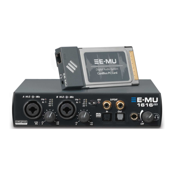
(3) Stereo Computer Speaker Outputs (with 1/8” jacks to connect powered speakers) The E-MU 02 CardBus Card The E-MU 02 CardBus Card is the heart of both systems. Its powerful hardware DSP processor allows you to use over 16 simultaneous hardware-based effects, which place minimal load on your computer’s CPU. -
Page 8: E-Mu 1616M System
You’ll want to keep up with the latest software and options for your E-MU digital audio system. You can find all of this, plus other helpful information, at the E-MU Website: http://www.emu.com. -
Page 9: Installation
• Multiple Digital Audio System sound cards are not supported. Please read the following sections as they apply to your system as you install the E-MU 02, paying special attention to the various warnings they include. Prior to installing the hardware, take a few moments to write down the 18-digit serial number, which is located on the back of the box and on the 02 CardBus Card. -
Page 10: Installing The Cardbus Card And Software
To plug the 02 CardBus Card into your computer Turn on your computer and wait for it to finish loading Windows. Insert the E-MU 02 CardBus card into the CardBus slot on your PC with the Note: Once the E-MU symbol up. -
Page 11: Note About Windows Logo Testing
Connect to balanced or unbalanced inputs and outputs. Warning: The E-MU 02 CardBus card has been designed to use readily available and inexpensive standard computer system cables. This makes it easy for you to find replacement cables if your original cable becomes damaged or lost. However, because these standard cables types are used for other purposes, you must use caution to avoid connecting the cables incorrectly. - Page 12 2 - Installation Connecting the MicroDock Creative Professional...
-
Page 13: Cardbus Card & Microdock
3 - CardBus Card & MicroDock The E-MU 02 CardBus Card The E-MU 02 CardBus card is the heart of the system and contains E-MU’s powerful E-DSP chip. The powerful hardware DSP on this little card leaves more CPU power free on your computer for additional software plug-ins and other tasks. -
Page 14: The Microdock
3 - CardBus Card & MicroDock The MicroDock The MicroDock The MicroDock connects to the E-MU 02 CardBus card via the EDI cable. The MicroDock provides (4) balanced analog inputs, (2) microphone preamp inputs, The MicroDock is (6) balanced line-level analog outputs, (3) stereo 1/8” outputs for connecting powered completely “hot... -
Page 15: Front Panel Connections
The S/PDIF out can be configured in either Professional or Consumer mode in the Session Settings menu. The MicroDock can also send and receive AES/EBU digital audio through the use of a cable adapter. See Cables - balanced or unbalanced? for details. E-MU 1616/1616M CardBus Digital Audio System... -
Page 16: Adat Optical Digital Input & Output
3 - CardBus Card & MicroDock The MicroDock ADAT Optical Digital Input & Output The ADAT optical connectors transmit and receive 8 channels of 24-bit audio using the Important: When ADAT type 1 & 2 formats. The word clock contained in the input data stream can be using any type of digital I/O such as S/PDIF or used as a word clock source. -
Page 17: Digital Connections
MIDI Sound Module SAMPLE TRIGGERS TRANSPOSE MASTER/GLOBAL SAMPLE MANAGEMENT DIGITAL PROCESSING INC/YES DEC/NO PRESET MULTIMODE PRESET MANAGEMENT PRESET DEFINITION DYNAMIC PROCESING MIDI 2 ENTER VOLUME ESCAPE DRIVE SELECT LOAD SAVE AUDITION TRIGGER MODE MIDI MIDI In E-MU 1616/1616M CardBus Digital Audio System... -
Page 18: Rear Panel Connections
Connect to (configured as 3 stereo pairs) (same as outputs 1-3) E-MU 02 CardBus Card Line Level Analog Inputs 4 balanced 24-bit, line-level, analog inputs are provided (1-2). These can be used to input any line level signal from keyboards, CD-players, cassette decks, etc. The analog inputs are assigned to mixer strips in the mixer application. -
Page 19: Computer Speaker Analog Outputs
Out to the MIDI In port of your synthesizer and MIDI Out of your synth to MIDI In of the MicroDock MIDI cable. EDI Connector (Card) Connects to the MicroDock to the E-MU 02 CardBus card using a CAT5-type computer cable. The cable supplied with the MicroDock is specially shielded to prevent unwanted RF emissions. - Page 20 3 - CardBus Card & MicroDock The MicroDock Creative Professional...
-
Page 21: The Patchmix Dsp Mixer
Fader Indicators Solo/Mute Buttons Monitor Volume/Balance User /Mute Controls Definable Main Current Main Mix WAVE Strip Scribble Strip Inserts Session Output Volume Controls Windows Source Audio Name & Meters (Direct Sound, Windows Media, etc.) E-MU 1616/1616M CardBus Digital Audio System... -
Page 22: Mixer Window
4 - The PatchMix DSP Mixer Overview of the Mixer Mixer Window The Mixer consists of four main sections. Application Toolbar Lets you manage sessions and show/hide the various views. Main Section Controls all the main levels, aux buses, and their inserts. This section also has a “TV”... -
Page 23: E-Mu Icon In The Windows Taskbar
Settings. Global Preferences Calls up the Global Preferences window. About PatchMix DSP Right-Click on the E-MU logo to view the “About PatchMix DSP” screen, which provides the software and firmware version numbers and other information. E-MU 1616/1616M CardBus Digital Audio System... -
Page 24: The Session
4 - The PatchMix DSP Mixer The Session The Session The current state of the PatchMix DSP mixer (fader settings, effects routings…every- thing!) can be saved as a Session. Whenever you create or modify a mixer setup, all you have to do is Save it to be able to recall it at a later time. Before you begin using PatchMix DSP, you need to set it up to be compatible with the other software applications you may be running. -
Page 25: Open Session
You can create your own templates by simply copying or saving sessions into the “Session Templates” folder (Program Files\Creative Professional\E-MU PatchMix DSP\Session Templates). The system model number in parenthesis (1616) must precede the template name in order to be recognized as a template. -
Page 26: Using External Clock
4 - The PatchMix DSP Mixer The Session The System Settings include the following: Note: if set to “External” without an • Internal/External Clock Selects between internal or external word clock source external clock present, as the master clock source for the system PatchMix DSP defaults to •... - Page 27 ADAT Output. The coaxial S/PDIF Output is disabled when S/PDIF optical is selected. • S/PDIF Output Format Selects between S/PDIF or AES/EBU format for S/PDIF . This sets the S/PDIF-AES status bit, but does not affect the signal level. E-MU 1616/1616M CardBus Digital Audio System...
-
Page 28: Input Mixer Strips
4 - The PatchMix DSP Mixer Input Mixer Strips Input Mixer Strips PatchMix DSP Input Mixer Strips are stereo except for the MicroDock Mic/Line inputs. Each input mixer strip can be divided into four basic sections. • Insert Section Effects, EQ, External/Host Sends & Returns can be inserted into the signal path. •... -
Page 29: Mixer Strip Creation
Click the top of the mixer strip you wish to delete. A red border appears around the strip, indicating that it is selected. Click on the Delete Mixer Strip button. See Overview of the Mixer E-MU 1616/1616M CardBus Digital Audio System... -
Page 30: Insert Section
4 - The PatchMix DSP Mixer Mixer Strip Creation Insert Section The Insert Section is next in line. PatchMix DSP effects can be selected from the Effects Palette and dropped into the insert locations. See “The Effects Palette”. Any number of effects can be inserted in series. -
Page 31: The Insert Menu
Right-Click over the Insert section. A pop-up dialog box appears. Select “Insert Send/Return (Physical Output and Input)” from the list of options. The following dialog box appears. E-MU 1616/1616M CardBus Digital Audio System... -
Page 32: Asio Direct Monitor Send/Return
4 - The PatchMix DSP Mixer Mixer Strip Creation If the source or Input destination you want to use is not available in the To Physical Output Insert list, they are probably Send/Return From Physical Input already being used elsewhere. Check the Panning input Strips, Inserts and Fader... -
Page 33: Meter Inserts
You want the input signal level to drive the 24-bit ADCs into their optimum range without clipping. A reading of 0dB on an input meter indicates signal clipping. Level --12dB Each bar of the meter equals 1dB. The yellow bars begin at -12dB below full scale. E-MU 1616/1616M CardBus Digital Audio System... -
Page 34: To Set The Input Levels Of A Strip
4 - The PatchMix DSP Mixer Mixer Strip Creation The insert meters are also useful to monitor incoming digital signals such as ADAT, ASIO or S/PDIF to make sure the mixer is receiving a proper signal level. They’re also great for troubleshooting, since you can place them virtually anywhere in the mixer. To Insert a Meter Right-Click on an Insert location of the mixer strip. -
Page 35: Trim Pot Insert
A/D converters in order to get maximum resolution and signal-to-noise ratio from the converters. The phase invert switch inverts the polarity of the signal. It is generally used to correct for balanced lines and mics that are wired backwards. E-MU 1616/1616M CardBus Digital Audio System... -
Page 36: Test Tone/Signal Generator Insert
4 - The PatchMix DSP Mixer Mixer Strip Creation To Add a Trim Pot Insert Right-Click over any of the Insert sections. A pop-up dialog box appears. Select Insert Trim Control from the list of options. A Trim Pot insert appears in the insert location. -
Page 37: Managing Your Inserts
Click on the Effect (in the Insert section) and select Effect in the TV display. Click the Solo button. Method #2 Right-Click over the Effect you want to Solo (in the Insert section). A pop-up dialog box appears. Select Solo Insert from the list of options. E-MU 1616/1616M CardBus Digital Audio System... -
Page 38: Aux Section
4 - The PatchMix DSP Mixer Mixer Strip Creation Aux Section The Auxiliary Sends tap the signal from the channel strips and sum them together before sending the mix to the Auxiliary Effects section. In a traditional mixing console, aux sends are used to send part of the signal to outboard effect devices, then return the effected signal back into the mix using the effect returns. -
Page 39: Pre Or Post Fader Aux Sends
Volume Fader & Mute affects both Aux Send Levels Fader Mute Send Return Amount Amount Side Chain Aux Bus 1 Send Return Amount Amount Side Chain Aux Bus 2 Main / Monitor Bus Output E-MU 1616/1616M CardBus Digital Audio System... -
Page 40: Level, Pan, Solo & Mute Controls
4 - The PatchMix DSP Mixer Mixer Strip Creation Level, Pan, Solo & Mute Controls The Pan control comes before the Level Control and Aux Sends in the signal flow. On stereo strips Pan Controls we use an unconventional pan section with two pan pots –... -
Page 41: Main Section
There is a stereo peak meter that indicates the signal strength for the main mix. The Monitor section has a volume, balance, and a mute control to cut off the monitor output. E-MU 1616/1616M CardBus Digital Audio System... -
Page 42: Tv Screen & Selectors
4 - The PatchMix DSP Mixer Main Section TV Screen & Selectors The “TV screen” at the top of the main section is a multi-function display and control center for the input and output routings and effect controls. The three buttons at the top of the display select the current function of the display—Effect, Inputs or Outputs. -
Page 43: Input
(or break) a connection. The Host Output screen displays and allows you to view the Host (ASIO or WAVE) outputs of the mixer. See “Insert Section” for information on how to connect the inserts. E-MU 1616/1616M CardBus Digital Audio System... -
Page 44: Auxiliary Effects & Returns
4 - The PatchMix DSP Mixer Main Section Auxiliary Effects & Returns The section immediately below the TV Screen is where you assign the Auxiliary Effects. The Wet/Dry mix In a traditional mixing console, auxiliary effects sends are used to send part of the signal setting in the effect should normally be set to to outboard effect devices, then return the effected signal back into the mix using the... -
Page 45: Output Section
This button completely cuts off the monitor output and provides a convenient way to instantly kill all sound without having to re-adjust the monitor level later. When the telephone rings, just hit the monitor mute to cut the noise. E-MU 1616/1616M CardBus Digital Audio System... - Page 46 4 - The PatchMix DSP Mixer Main Section Creative Professional...
-
Page 47: Effects
Effects Chains and the folders that contain them. For more information on Effects Chains, see “FX Insert Chains” on page 48. New Folder Icon Effect Categories Core Effects Multi-Effects Distortion Lo-fi Drums & Percussion Environment Equalization Guitar Morpher Multi Effects Reverb Synths & Keys Vocal E-MU 1616/1616M CardBus Digital Audio System... -
Page 48: Fx Insert Chains
5 - Effects The Effects Palette To Select an Effect Click the FX button to bring up the Effects Palette. The effect palette contains numerous folders containing effects presets. Click on any folder to open it. Select the effect you wish to use by clicking on it with the left mouse button and The order of effects in while continuing to hold the mouse button, drag the effect into the desired location a chain can have a big... -
Page 49: Creating, Renaming & Deleting Categories Or Presets
Right-click on the category folder you wish to rename. A pop-up selection box appears. Select “Rename Category”. A pop-up dialog box appears, asking you to “Enter New Category Name.” Click OK to rename the folder or Cancel to cancel the operation. E-MU Digital Audio System... -
Page 50: Fx Edit Screen
5 - Effects FX Edit Screen FX Edit Screen Click on an FX Insert to display the parameters for that effect. If an insert effect is not Note: Effects have to selected, the FX display will read “No Insert”. be placed into an insert location before you can Most effects have a wet/dry mix parameter to control the ratio of effect-to-plain signal. -
Page 51: User Preset Section
Click on the Edit button. A pop-up menu appears. Select New. A pop-up dialog box appears asking you to name the new preset. Name the preset and click OK. Your new preset is now saved. E-MU Digital Audio System... -
Page 52: Core Effects And Effects Presets
Core Effects and Effects Presets The Core Effects cannot be removed or copied. Effect presets (stored in “C:\Program Hint: You can open Files\Creative Professional\E-MU 1616\E-MU PatchMix DSP\Effect Presets”) can be the effects presets with “NotePad” or other word copied, e-mailed or shared like any other computer file. -
Page 53: List Of Core Effects
1-Band EQ Stereo Delay 1500 1-Band EQ Compressor Mono Delay 250 Compressor Mono Delay 1500 Compressor Chorus Mono Delay 250 Chorus Mono Delay 1500 Auto-Wah Flanger 4-Band EQ 3-Band EQ Total Effects Total Effects Total Effects E-MU Digital Audio System... -
Page 54: Core Effects Descriptions
5 - Effects Core Effects Descriptions Core Effects Descriptions 1-Band Para EQ This single band parametric equalizer is useful +15dB when you just want to boost or cut a single range of frequencies. For example, if you just want to Boost brighten up the lead vocal a bit, you might Width... -
Page 55: 3-Band Eq
Sets the amount of cut (-) or boost (+) of the low frequency shelf. Range: -24dB to +24dB Low Corner Freq. Sets the frequency where the signal begins getting cut or boosted with the Low Gain control. Range: 50Hz to 800Hz E-MU Digital Audio System... -
Page 56: 4-Band Eq
5 - Effects Core Effects Descriptions 4-Band EQ This 4-band equalizer provides two shelving filters at the high and low ends of the frequency range and two fully parametric bands in the center. Up to ±24 dB of boost or cut is provided for each band. -
Page 57: Auto-Wah
Sweep Range Controls the amount of “wah” sweep. Range: 0% to 100% Center Frequency Sets the initial bandpass filter frequency. Range: 80Hz to 2400Hz Bandwidth Sets the width of the bandpass filter. Range: 1Hz to 800Hz E-MU Digital Audio System... -
Page 58: Chorus
5 - Effects Core Effects Descriptions Chorus An audio delay in the range of 15-20 milliseconds is too short to be an echo, but is perceived by the ear as a distinctly separate sound. If we now vary the delay time in this range, an effect called chorus is created, which gives the illusion of multiple sound sources. -
Page 59: Basic Controls
Sets the ratio of input signal level to output signal level, or “how much” compression will be applied. Range: 1:1 to ∞:1 Post Gain Amplifies the signal after it has been compressed to bring up the volume. Range -60dB to +60dB E-MU Digital Audio System... -
Page 60: Distortion
5 - Effects Core Effects Descriptions Parameter Description Attack Time Controls how quickly the gain is turned down after the signal exceeds the threshold. Range .1ms to 500ms Release Time Controls how fast the gain is returned to its normal setting after the signal has fallen below the threshold. -
Page 61: Flanger
flanging effect. Range 05 to 100% LFO Waveform Selectable between Sine or Triangle wave. LFO L/R Phase Controls the stereo width by adjusting the phase difference between the left and right sweeps. Range: -180° to +180° E-MU Digital Audio System... -
Page 62: Freq Shifter
5 - Effects Core Effects Descriptions Freq Shifter This unusual effect is sometimes called “spectrum shifting” or “single sideband modulation”. Frequency shifting shifts every frequency in the signal by a fixed number of Hz which causes the harmonics to lose their normal relationship. The more common pitch shifter, in contrast, preserves the harmonic relationships of the signal and so is better suited to creating “musical”... -
Page 63: Leveling Amp
Post Gain Amplifies the signal after it has been compressed to bring up the volume. Range 0dB to 36dB E-MU Digital Audio System... -
Page 64: Lite Reverb
5 - Effects Core Effects Descriptions Lite Reverb Reverberation is a simulation of a natural space such as a room or hall. The Lite Reverb algorithm is designed to simulate various rooms and reverberation plates while using fewer DSP resources than the Stereo Reverb. Up to five Lite Reverbs can be used at once. Decay time defines the time it takes for the reflected sound from the room to decay or die away. -
Page 65: Mono Delays - 100, 250, 500, 750, 1500, 3000
Range: 1 millisecond to 3 seconds Feedback Sets the amount of delayed signal that will be recirculated through the delay line. Range: 0% to 100% High Freq. Rolloff Damps high frequencies in the feedback path. Range: 0% to 100% E-MU Digital Audio System... -
Page 66: Phase Shifter
5 - Effects Core Effects Descriptions Phase Shifter A phase shifter produces a fixed number of peaks and notches in the audio spectrum which can be swept up and down in frequency with a low frequency oscillator (LFO). This creates a swirly, ethereal sound with harmonically rich sound sources of a type of pitch shift with simpler sounds. -
Page 67: Speaker Simulator
Modeled from an American, 1960’ s era, 2-speaker combo amplifier. 4 x 12 Combo Modeled from an American, 1960’ s era, 4-speaker amplifier set. Metal Stack 1 & 2 Modeled from a modern era, power amplifier stack. E-MU Digital Audio System... -
Page 68: Stereo Delays - 100, 250, 500, 750, 1500
5 - Effects Core Effects Descriptions Stereo Delays - 100, 250, 500, 750, 1500 The Stereo Delays are true stereo delay lines in that the left and right channels are kept entirely separate from each other. The delay number refers to the maximum delay time that can be produced by the delay lines. - Page 69 High Freq. Damping Sets the rate at which high frequencies die away. Range: -10.0 to +3.0 damping factor Low Freq. Damping Sets the rate at which low frequencies die away. Range: -10.0 to +3.0 damping factor E-MU Digital Audio System...
-
Page 70: Vocal Morpher
5 - Effects Core Effects Descriptions Vocal Morpher This unique effect allows you to select two vocal phonemes and morph between them using an LFO. Phonemes are the consonants and vowels we use in articulating speech sounds and these sounds are very distinctive and evocative. 30 different phonemes are available and these can be shifted up or down in pitch for even more effects. -
Page 71: E-Mu Powerfx
5 - Effects E-MU PowerFX E-MU PowerFX The hardware-accelerated effects of the E-MU Digital Audio System can also be used as E-MU PowerFX are not VST inserts in Cubase. E-MU PowerFX allow you to use PatchMix DSP effects from available at 88.2kHz, 96kHz, 176.4kHz and... - Page 72 Using any driver other than “E-MU ASIO” may Launch Cubase or Cubasis. produce undesirable Instantiate E-MU PowerFX in an Insert or Aux Send location within Cubase. results when using E-MU PowerFX. Press the Insert Edit button in Cubase to bring up the E-MU PowerFX plug-in window shown on the previous page.
-
Page 73: Automating E-Mu Powerfx
• If DSP resources ARE available, but no Hardware I/O Paths are available, the plug-in will run in soft pass-through mode. • If the sample rate is changed in the middle of a E-MU PowerFX session, E-MU PowerFX plug-ins will be bypassed, since the hardware effects cannot operate at 88kHz, 96kHz, 176.4kHz or 192kHz. - Page 74 5 - Effects E-MU PowerFX E-MU PowerFX Compatibility Chart Extra Application Name Compatible? Note Render Buffers Steinberg Cubase VST 5.1 Steinberg Cubase SX 1 Steinberg Cubase SX 2 Instrument Freeze triggers error if not in render mode. Steinberg Cubase LE...
-
Page 75: Rendering Audio With E-Mu Powerfx
Stuttering in the audio can occur when rendering with SoundForge or any version of Steinberg WaveLab. This problem is caused by discontinuities in the first few audio buffers as they are fed by WaveLab to E-MU PowerFX. The problem can be eliminated by following these guidelines. -
Page 76: E-Mu Vst E-Wire
VST chain. In addition, E-Wire also allows you to insert outboard audio gear into the VST environment. E-Wire has three main components: Note: It’ s easier to use E-MU PowerFX instead of • A VST plug-in which handles the audio routing to PatchMix DSP. E-Wire if you just want to use the hardware effects. -
Page 77: E-Delay Compensator
E-Wire on any other audio tracks. That’s it. E-Delay Compensator As audio is transferred back and forth between the VST host application and the E-MU sound hardware, a delay in the audio stream is incurred. Normally this delay is compen- sated for automatically by the host application, but not all VST host applications support this automatic compensation. -
Page 78: E-Delay Compensator Use
5 - Effects E-MU VST E-Wire Currently automatic delay compensation is supported by the Steinberg 2.0 family (Nuendo 2.x, Magix Samplitude 7.x, Cubase SX 2.0, Cubase LE 2.0,), and Sonar (using the but not, unfortunately, by Steinberg Cubase VST 5.1 and Cakewalk VST adapter 4.4.1,... -
Page 79: Grouping Tracks
E-Delay Compensator on the output of the group or bus. • E-MU Digital Audio System and PatchMix DSP must be installed. • E-Wire is compatible with Cubase SX/SL/LE, Cubase VST, Wavelab, and Cakewalk Sonar (via DirectX-VST adapter) among others. - Page 80 5 - Effects E-MU VST E-Wire Creative Professional...
-
Page 81: Using High Sample Rates
E-MU 1616 System at 176kHz or 192kHz At the 176.4kHz or 192kHz sample rates you have 4 inputs and 10 output channels. There are three possible input configurations when using the E-MU 1616 system at these high sample rates. 1. Keep all Analog I/O, but lose S/PDIF 2. - Page 82 6 - Using High Sample Rates Overview At the 192kHz sample rate, you may choose one of these three options: 1. Keep all Analog I/O, but lose S/PDIF 3. Keep S/PDIF & ADAT, but lose 2. Keep all Analog I/O, but lose ADAT Line Inputs 2L/2R &...
-
Page 83: Wdm Recording And Playback Behavior
6 - Using High Sample Rates Overview E-MU 1616 Inputs & Outputs at 176.4k or 192k Source Input Output Input Output Input Output Analog Analog & S/PDIF S/PDIF Analog Analog & S/PDIF & ADAT & ADAT & ADAT & ADAT... - Page 84 6 - Using High Sample Rates Overview Creative Professional...
-
Page 85: Appendix
Useful Information Cables - balanced or unbalanced? All inputs and outputs on the E-MU Digital Audio System are designed to use either balanced or unbalanced cables. Balanced signals provide an additional +6dB of gain on the inputs and are recommended for best audio performance, although unbalanced cables are fine for most applications. -
Page 86: Adapter Cables
This simple adapter cable allows you to receive AES/EBU digital audio via the S/PDIF input on the E-MU 02 CardBus card. This cable may also work to connect S/PDIF out from the 02 CardBus card to the AES/EBU input of other digital equipment. -
Page 87: Grounding
To Improve the Appearance Settings: Open the Windows Control Panel. (Start, Settings, Control Panel). Select System. Select the Advanced Settings tab. Under Visual Effects, select Adjust for Best Performance. Click OK. E-MU 1616/1616M CardBus Digital Audio System... -
Page 88: Technical Specifications
7 - Appendix Technical Specifications Technical Specifications Specifications: 1616 System GENERAL 44.1 kHz. 48 kHz, 96 kHz, 192 kHz from internal crystal Sample Rates Accepts externally supplied clock from S/PDIF or ADAT 16 or 24-bits Bit Depth 100MIPs custom audio DSP . - Page 89 24 ohm load: < -43 dB (1kHz at 0 dBFS) Stereo Crosstalk: 600 ohm load: < -100 dB (1kHz at 0 dBFS) 100 mW (24Ω load) Max Output Power: 22 ohms Output Impedance: 85 dB Gain Range: E-MU 1616/1616M CardBus Digital Audio System...
- Page 90 7 - Appendix Technical Specifications Specifications: 1616 System CARD HEADPHONE AMP +0.05/-0.0 dB, 20 Hz - 20 kHz Frequency Response: 24 ohm load: -80 dB (0.01%) THD+N: 65 ohm load: -85 dB (0.0056%) 600 ohm load: -96 dB (0.0016%) 116 dB (A-weighted, 22kHz BW)
- Page 91 Frequency Response -98 dB (.0012%) (-1dBFS, 20kHz BW) THD + N 112 dB (A-weighted, 20kHz BW SPCL) 112 dB (A-weighted, 20kHz SPCL) Dynamic Range < -115 dB, 1kHz Stereo Crosstalk 560 ohms Output Impedance E-MU 1616/1616M CardBus Digital Audio System...
- Page 92 7 - Appendix Technical Specifications Specifications: 1616 System MIC PREAMP/LINE INPUT HI-Z LINE INPUT -15 dB to +51 dB Gain Range: 19.5 dbV Max Level: -101 dB (.0009%), -1 dBFS, 20kHz BW THD+N: 110 dB, (A-weighted, 20kHz BW) SNR: 110 dB, (A-weighted, 20kHz BW)
- Page 93 44.1kHz, 48 kHz, 88.2kHz, 96 kHz, 176.4kHz, 192 kHz Internal Crystal Sync: ADAT, S/PDIF (optical or coaxial) SRSync SourceRMS jitter in picoseconds RMS JITTER @ 44.1K (Measured via Audio Precision 2) 44.1 kHz internal Crystal 596ps 44.1 kHz Optical Input 795ps E-MU 1616/1616M CardBus Digital Audio System...
- Page 94 7 - Appendix Technical Specifications Dimensions & Weight MICRODOCK 2.27 lb / 1.03 kg MicroDock Weight: W: 7.25" H: 1.625" L: 7.75" Dimensions: W: 184 mm H: 41 mm L: 196 mm 02 CardBus Card 0.095 lb / 0.043 kg Weight: W: 2.125"...
-
Page 95: Internet References
KVR Forum ..........http://www.kvr-vst.com/forum/ Driver Heaven Forum ......http://www.driverheaven.net/search.php?s MIDI Addict Forum........ http://forum.midiaddict.com/search.php Home Recording Forum ......http://homerecording.com/bbs/ search.php?s=d866b60193933eb726660e7b d90dfb27 Sound-On-Sound Forum ....... http://sound-on-sound.com/forum/ Studio-Central Cafe Forum ....http://studio-central.com/phpbb/search.php Sound Card Benchmarking ....http://audio.rightmark.org E-MU 1616/1616M CardBus Digital Audio System... -
Page 96: Declaration Of Conformity
7 - Appendix Internet References Declaration of Conformity E-MU Systems Trade Name: EM8850 Model No.: EM8870 EM8871 E-MU Systems Responsible Party: 1500 Green Hills Road, Address: Scotts Valley, CA 95066 U.S.A. This device complies with Part 15 of the FCC rules. Operation is subject to the following... -
Page 97: Compliance Information
Directive for using connection cables shorter than 3 meters (9.8 feet). Notice If static electricity or electromagnetism causes data transfer to discontinue midway (fail), restart the application or disconnect and connect the Firewire cable again. E-MU 1616/1616M CardBus Digital Audio System... - Page 98 7 - Appendix Internet References Creative Professional...
-
Page 99: Index
Echo, creating 65 Balance Control, monitor 45 E-Delay Compensator 77 Balanced Cables 18 Edge, distortion 60 Block Diagram, mixer 22 EDI Cable 11 Bypass EDI Connector 19 effect insert 50 insert 37 send/return insert 42 E-MU 1616/1616M CardBus Digital Audio System... - Page 100 70 bypass 37 E-MU 02 CardBus Card delete 37 description 13 menu 31 installing 10 meter 34 E-MU Icon, in taskbar 23 mixer strip 30 Envelope, reverberation 64 solo 37 E-Wire 76 types 30 Exit PatchMix DSP Services 23 Interface...
- Page 101 Parametric EQ, setting up 55 aux send 38 PatchMix DSP, disabling 23 fader 40 Peak Meters 33 insert 30 Phantom Power 15 label 40 description 87 mute button 40 Phase Invert 35 new 29 E-MU 1616/1616M CardBus Digital Audio System...
- Page 102 24 Pink Noise Generator 36 templates 25 Playing CDs 29 at 176k/192k 25 Post Gain, leveling amp 63 Setting Up the E-MU Digital Audio System 9 Power Switch, microdock 11 Settings PowerFX 71 I/O 26 resource availability 73...
- Page 103 Wah-Wah 57 WDM Recording & Playback Behavior 83 Wet/Dry Mix, effects 50 White Noise Generator 36 Window Appearance Settings 87 Windows Media Player 29 Windows Taskbar, E-MU icon 23 XLR Connector 15 Zero-Latency Monitoring 32 E-MU 1616/1616M CardBus Digital Audio System...
- Page 104 Index Creative Professional...