Advertisement
Quick Links
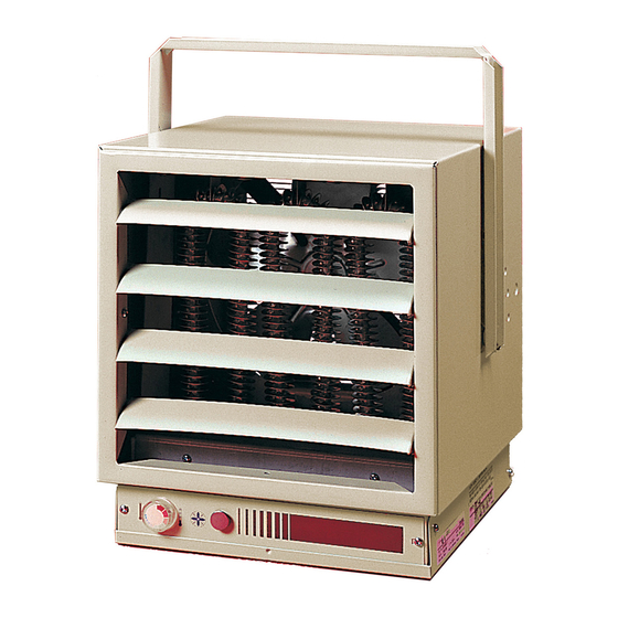
Electric Unit Heaters
EUH-B Series
impOrTanT inSTrUCTiOnS
When using electrical appliances, basic precautions should
always be followed to reduce the risk of fire, electric shock
and injury to person, including the following:
1.
Read all instructions before using this heater.
2.
A heater has hot and arcing or sparking parts inside. Do
not use it in areas where gasoline, paint or flammable
liquids are used or stored.
3.
This heater is hot when in use. To avoid burns, do not let
bare skin touch hot surfaces. If provided, use handles
when moving this heater. Keep combustible materials
such as: furniture, pillows, bedding, papers, clothes and
curtains away from heater.
4.
To prevent a possible fire, do not block air intakes or
exhaust in any manner. Do not use on soft surfaces like
a bed where openings may become blocked.
5.
Do not insert or allow foreign objects to enter any venti-
lation or exhaust opening as this may cause an electric
shock or fire, or damage the heater.
SaVE THESE inSTrUCTiOnS
installation instructions
Warning:
Wiring procedures and connections should
be in accordance with the National Electric code (NEC) and
local codes.
FOr HOriZOnTaL Or VErTiCaL airFLOW
PERMANENT OR SUPPLEMENTARY ELECTRIC FORCED
AIR HEATING FROM THE SAME VERSATILE UNIT
These heavy-duty heaters provide spot heating for hard to
heat areas, or they can be used as the primary source of
heat for areas not reached by an existing heating system.
The fan and motor are carefully matched to insure quiet,
trouble-free operation and fan blades are precision balanced
before installation.
Heaters in all capacities (3, 5, 7-1/2, 10 or 12kw) have the
same dimensions, and use the same mounting brackets. All
components and controls, including thermostat, transformers,
relays, and switches are enclosed inside the case. Wiring
is simple and all heaters can operate from a single power
source.
HEaTEr LOCaTiOn
Unit heaters should be located along outside walls to provide
perimeter air circulation. The discharge air should wipe the
walls without blowing directly on them. (Figure 1)
•
Small rooms
- can be heated by one or two units.
Locate the unit heater(s) to provide circular air movement
within the space.
•
Large rooms
- requiring multiple unit installations. Units
should be located so that the discharge air from one unit
supports the discharge from another unit and provides a
circular air movement.
•
remote thermostats
- should be located on interior
walls or posts away from heat sources, cold drafts, and
away from heater discharge streams.
mOUnTing UniT HEaTEr(S
Heater should be mounted a minimum of ten (10) inches
from walls and six (6) feet above floor (8 feet for vertical air
flow) with the discharge parallel to or away from wall.
•
mOUnTing BraCKET
a mounting bracket packed separately in the carton.
Secure the bracket to threaded attachment points on
the sides of the heater with two bolts (provided). Select
desired angle of tilt (Horizontal, 15, 30, 45, 60, 75, or
Vertical), remove corresponding knockouts on sides
of the heater, then screw the remaining two bolts into
the threaded holes in the bracket so that the bolts pass
through the knockout holes. The unit is now ready for
hanging.
•
CEiLing mOUnTing
the ceiling using the center hole in the bracket or the two
holes on either side of the center hole. The Unit mounting
bracket may be attached directly to the ceiling.
•
WaLL mOUnTing
- The heater may also be mounted
to a wall with accessory wall bracket, Part # EUHWB.
The wall bracket attaches to the center hole of the unit
mounting bracket.
Figure 1
EXpOSED OUTSiDE WaLL
SmaLL rOOm
EXpOSED OUTSiDE WaLL
Wiring:
1.
Connect the heater only to the voltage and frequency
specified on the nameplate.
2.
All wiring to be in accordance with local and national
electric codes.
3.
Remove two screws securing the access door (See
Figure 2) and swing the door down to expose the wiring
and control compartment.
4.
Three knockouts are provided at the back of the heater
for power and control wiring. (See Figure 2)
5.
Rough-in branch circuit wiring to the heater using wire
)
- The heater is shipped with
- Fasten the heater securely to
LargE rOOm
7202450001R06
Advertisement

Related Manuals for Dimplex EUH-B Series


Summary of Contents for Dimplex EUH-B Series
-
Page 1: Important Instructions
Electric Unit Heaters EUH-B Series walls or posts away from heat sources, cold drafts, and impOrTanT inSTrUCTiOnS away from heater discharge streams. When using electrical appliances, basic precautions should mOUnTing UniT HEaTEr(S always be followed to reduce the risk of fire, electric shock... - Page 2 This Warranty is transferable by the original consumer purchaser of the product. Any claims under this Warranty must be submitted CaUTiOn: Disconnect the built-in thermostat in writing to the Service Manager, Dimplex North America Ltd., 1367 • Fan only Switch - An optional “Fan only”...
-
Page 3: Replacement Parts
2400170900RP 2200212000RP EUH12B84CT 2100120500RP 2400170900RP 2200212400RP 1367 Industrial Road Cambridge ON Canada N1R 7G8 1-888-346-7539 www.dimplex.com In keeping with our policy of continuous product improvement, we reserve the right to make changes without notice. © 2011 Dimplex North America Limited...