Table of Contents
Advertisement
Advertisement
Table of Contents

Related Manuals for Bosch D2071A


Summary of Contents for Bosch D2071A
- Page 1 D2071A Operation & Installation Guide Fire Alarm Control Panel...
-
Page 2: Table Of Contents
D2071A | Operations & Installation Guide | Contents Contents Overview ................4 Secondary Power Supply and Communicator ............4 Charging Circuit (12 VAC Mode Only) ... 14 RFI and Lightning Protection ....... 4 2.7.1 Battery ..............14 Materials Included ..........4 2.7.2... - Page 3 D2071A | Operations & Installation Guide | FCC Notice Figures FCC Notice The D2071A Fire Alarm Control Panel (FACP) Figure 1: D2071A Control Panel ........7 generates, uses, and can radiate radio frequency energy. Figure 2: Stand-Alone Installation ........8...
-
Page 4: Overview
D2071A | Operations & Installation Guide | Overview Overview Materials Included The D2071A Fire Alarm Control Panel (FACP) is a 1.3. 1 D2071A three-zone digital alarm communicator transmitter The D2071A is shipped completely assembled and (DACT) used in limited stand-alone applications or in... -
Page 5: Mandatory Connections
To comply with the NFPA 72 Central Station Fire or NFPA 72 Remote Station Signaling Service, connect the D2071A as described in Table 2. The Class “A” and Class “B” circuits are mandatory connections for the slave and stand-alone applications. Refer to Section 2.0 Installation on page 8 for wiring instructions. -
Page 6: Slave Communicator Applications
System restoral Slave Communicator Applications • 2300 Hz acknowledgment tone To use the D2071A as a slave communicator that only provides signaling connections, connect the D2071A to • BFSK or 3 x 1, 40 pulses per second (PPS), single an existing UL Listed NFPA 72 FACP. Use the D2071A... -
Page 7: Phone Line Trouble Led
Mounting tabs (Item 7 in Figure 1) are located on each Install a D136 Relay in this socket when using the end of the D2071A to provide a way to mount the optional Initiating Circuit Alarm Relay (Item 11 in D2071A with screws. -
Page 8: Installation
When you are using the D2071AC, mount the D4103R Enclosure and have a qualified electrician connect a 110 VAC or 120 VAC power source to the black and white leads on the transformer. Before beginning the D2071A installation, ensure the power source is turned off. Figure 2: Stand-Alone Installation... -
Page 9: Figure 3: Slave Communicator Installation
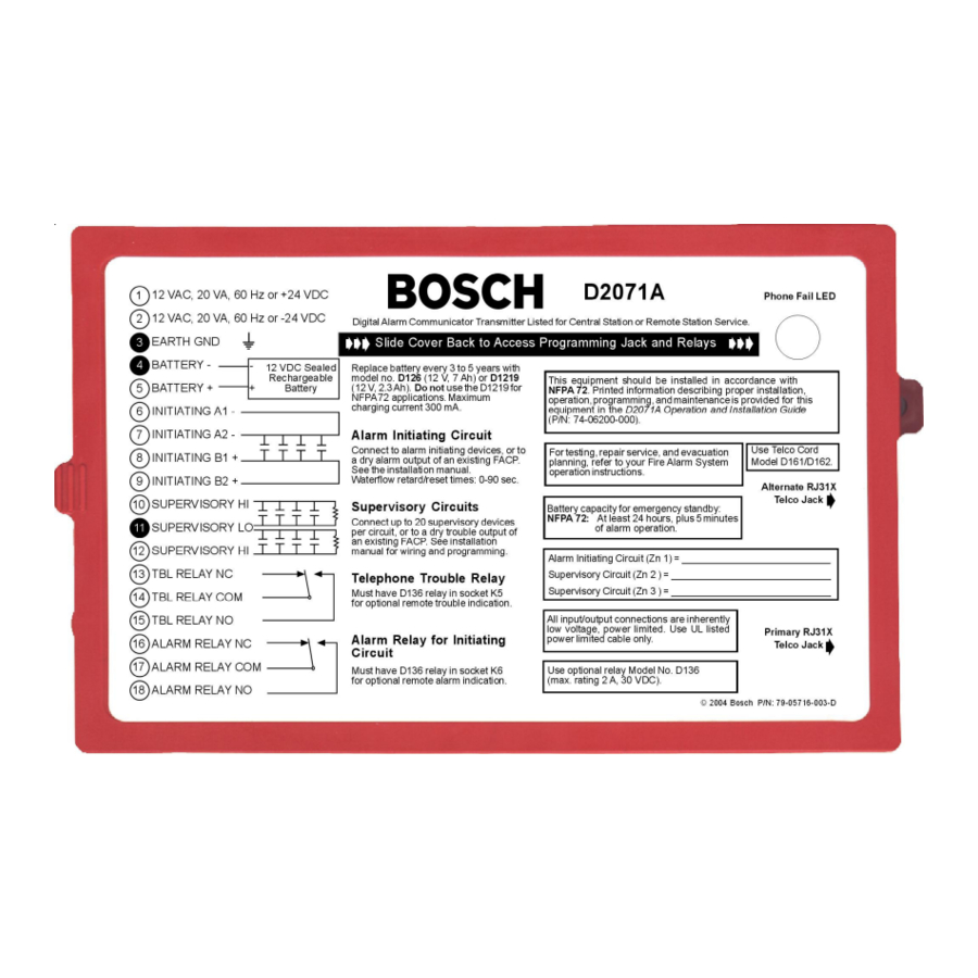
D2071A | Operations & Installation Guide | 2.0 Installation Figure 3: Slave Communicator Installation 12 VAC, 20 VA, 60 Hz, OR + 24 VDC 12 VAC, 20 VA, 60 Hz, OR – 24 VDC EARTH GND BATTERY – BATTERY + INITIATING A1 –... -
Page 10: Earth Ground Wiring
D2071A | Operations & Installation Guide | Installation To determine the circuit’s electrical condition: Earth Ground Wiring 1. Ensure the D2071A is powered up and the loops are Only use Terminal 3, not telephone or in a normal condition. electrical ground, for earth ground 2. -
Page 11: Wiring
• When the alarm initiating circuit is normal for the time specified in reset time, the D2071A sends a Restoral Zone 1 Report. Generally, the reset time is set to approximately half the retard time. -
Page 12: Mode 3
Slave Communicator Applications Mode 3 (Figure 6) uses a 1.8 k EOL resistor at the end 1. When connecting the D2071A to an FACP, use the of the loops. Trouble Reports are sent on an open Mode 3 configuration for the slave communicator circuit. -
Page 13: Wiring
Terminals 16, 17, and 18. Do not use the D2071A 20 VA transformer and standby battery. You can also Standby Battery to provide a power output for the connect the D2071A to the 24 VDC output of an FACP. circuit. Use either method for NFPA 72 applications. -
Page 14: Vdc Mode
Terminals 1 and 2 used to generate the D2071A Terminal 5. Battery Reports with the D2071A in 24 VDC Mode. If Parallel Activation on Powerup: The Phone Line the voltage falls below 11.1 VDC, the D2071A does not Trouble Buzzer, Phone Line Trouble Relay, and Phone operate. -
Page 15: Vac Battery Discharge And Recharge Schedule
Each line is sniffed once a minute if both lines are good. recharge schedule. If a line is determined to be in trouble, the D2071A steps up the test rate and sniffs once every 10 sec. If the Telephone Connections... -
Page 16: Call Routing
FACP, leave room on the bottom of the Phone Number 2 Alternate Line enclosure for the battery. Do not mount the D2071A in a location where it restricts the flow of cooling air to the Phone Number 1 Alternate Line FACP power supply or a similar device. -
Page 17: Screw Mounting
Adhesive Strip Mounting Figure 9: Inserting Cable Tie You can use two adhesive strips (provided) to mount the D2071A in the enclosure with the FACP, or in a separate enclosure. 1. Select a location with a smooth, clean, and dry mounting surface. -
Page 18: Programming
Manual (P/N: 74-06176-000). Become familiar with the D5200 Programmer Operation Manual before programming any Bosch product. When programming the D2071A DACT with the D5200 Programmer, ensure the programmer has the 2071 Product Handler Program. Refer to the D5200 Programmer Operation Manual for the updated D5200 instructions. -
Page 19: Function Keys
The D5200 Programmer emits four distinct sounds to notify users of key presses, data acceptance or rejection, You can program the D2071A before installation. If the and system errors (Table 8). D2071A is powered and not connected to a telephone... -
Page 20: Program Modules
D2071A is powered, and Editing the Program Record • controls the loop response times. Each D2071A DACT programming option is listed as it appears in the Programmer Display. The default, a set of Account # selections, and a description follows. -
Page 21: Table 9: Special Dialing Characters
D2071A | Operations & Installation Guide | 4.0 Program Record Table 9: Special Dialing Characters When programming the primary and alternate telephone numbers, ensure the primary telephone number is different from Selection Dialing Effect Description the alternate telephone number. (*) character Accesses special telephone features. - Page 22 D2071A | Operations & Installation Guide | Program Record Reset Time Default: Selections: 0 to 90 Use to program the reset timer for the Class “A” Alarm Initiating Circuit (Zone 1). Enter the number of seconds you want for the reset time. Before the retard timer sets...
-
Page 23: Receiver Reports
Open or short on alternate telephone line. TROUBLE ZN E Communications failure after ten attempts to transmit a report. The reports in the D2071A buffer when a communications failure occurs are not transmitted. The buffer is cleared. Test timer failed to report on the first attempt. -
Page 24: Troubleshooting
The telephone line should meter a communicator does minimum of 20 VDC when the D2071A is idle (on not transmit its hook). If the voltage is below 20 VDC, meter for reports. -
Page 25: Trouble Zone E
D2071A’s dialing speed. 2. D5203 Programmer Cord is securely plugged into • The D2071A might be getting a busy signal at the the D5206 Adapter. first dialing attempt. The receiver’s call load might 3. D5203 Programmer Cord is plugged into the be too great. -
Page 26: Zones Problems
A TROUBLE ZN 9 Report tells you there is a problem Table 12: Zone Problems with the battery when the D2071A is in 12 VAC Mode. It also indicates there is a problem with the power Zone 1 Alarm Initiating Circuit supply in the 24 VDC Mode. -
Page 27: Specifications
D2071A | Operations & Installation Guide | 7.0 Specifications Specifications Table 13: Specifications Power Input 12 VAC, 20 VA with 12 VDC battery 24 VDC Operating Current Specification 12 VAC Mode 24 VAC Mode Idle Current 29.5 mA 30.0 mA Battery Charging 51.0 mA... - Page 28 Bosch 130 Perinton Parkway Fairport, NY 14450-9199 USA Customer Service: (800) 289-0096 Technical Support: (888) 886-6189 © 2004 Bosch 74-06200-000-F...