Table of Contents
Advertisement
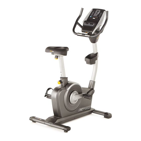
www.epicfit.com
Model No. EPEX13912.2
USER’'S MANUAL
Serial No.
Write the serial number in the
space above for reference.
Serial Number
Decal (under frame)
QUESTIONS?
If you have questions, or if parts
are damaged or missing, DO NOT
CONTACT THE STORE; please
contact Customer Care.
IMPORTANT: Please register this
product (see the limited warranty
on the back cover of this manual)
before contacting Customer Care.
VISIT OUR WEBSITE:
www.epicfit.com
Chat: Mon.––Fri. 6 a.m.––7 p.m. MT
CALL:
1-855-EPIC-FIT (1-855-374-2348)
Mon.––Fri. 6 a.m.––7 p.m. MT
EMAIL:
productsupport@epicfit.com
CAUTION
Read all precautions and instruc-
tions in this manual before using
this equipment. Keep this manual
for future reference.
Advertisement
Table of Contents

Related Manuals for Epic A17u Bike


Summary of Contents for Epic A17u Bike
- Page 1 www.epicfit.com Model No. EPEX13912.2 USER’’S MANUAL Serial No. Write the serial number in the space above for reference. Serial Number Decal (under frame) QUESTIONS? If you have questions, or if parts are damaged or missing, DO NOT CONTACT THE STORE; please contact Customer Care.
-
Page 2: Table Of Contents
TABLE OF CONTENTS WARNING DECAL PLACEMENT ............. . . 2 IMPORTANT PRECAUTIONS . -
Page 3: Important Precautions
IMPORTANT PRECAUTIONS WARNING: To reduce the risk of serious injury, read all important precautions and instructions in this manual and all warnings on your exercise bike before using your exercise bike. ICON assumes no responsibility for personal injury or property damage sustained by or through the use of this product. -
Page 4: Before You Begin
BEFORE YOU BEGIN Thank you for selecting the revolutionary EPIC A17U reading this manual, please see the front cover of this ™™ exercise bike. Cycling is an effective exercise for manual. To help us assist you, note the product model increasing cardiovascular fitness, building endurance, number and serial number before contacting us. -
Page 5: Part Identification Chart
PART IDENTIFICATION CHART Use the drawings below to identify the small parts needed for assembly. The number in parentheses below each drawing is the key number of the part, from the PART LIST near the end of this manual. The number following the key number is the quantity needed for assembly. -
Page 6: Assembly
ASSEMBLY •• To watch an assembly •• Left parts are marked ““L”” or ““Left”” and right parts video, go to are marked ““R”” or ““Right.”” http://productvideo.co/ assembly/dsg/epic or •• To identify small parts, see page 5. use your mobile phone or smartphone to read ••... - Page 7 3. Orient the Seat Post (6) as shown. Next, loosen the Seat Post Knob (49) a few turns, pull the Seat Post Knob outward, and insert the Seat Post (6) into the Frame (1). Slide the Seat Post (6) upward or downward to the desired position, and then release the Seat Post Knob (49) into one of the adjustment holes Adjustment...
- Page 8 6. Orient the Front Shield Cover (7) and the Upright (4) as shown. Slide the Front Shield Cover onto the Upright. Wire Tie While a second person holds the Upright (4) near the Frame (1), tie the lower end of the wire tie in the Upright to the Main Wire (58).
-
Page 9: Untie And Discard The Wire Tie (Not Shown) On The
8. Orient the Handlebar (5) as shown. Avoid pinching Tip: Avoid pinching the Pulse Wire (17) and the wires the Main Wire (58). Attach the Handlebar (5) to the Pivot Bracket (35) with six M8 x 13mm Screws (72). 9. Untie and discard the wire tie (not shown) on the Main Wire (58). - Page 10 11. Tip: It may be necessary to turn the Adjustment Knob (27) and adjust the angle of the Pivot Bracket (35). Attach the Lower Pivot Cover (12) to the Pivot Bracket (35) with two M4 x 12mm Screws (75). Make sure that the indicated wire (A) is not covered by the Lover Pivot Cover (12) (see the drawing in step 12).
- Page 11 14. Identify the Left Pedal (21). Using the included flat wrench, firmly tighten the Left Pedal (21) counterclockwise into the Left Crank Arm (19). Strap Firmly tighten the Right Pedal (not shown) clockwise into the Right Crank Arm (not shown). Adjust the strap on the Left Pedal (21) to the desired position, and press the ends of the strap onto the tabs on the Left Pedal.
-
Page 12: The Chest Heart Rate Monitor
THE CHEST HEART RATE MONITOR HOW TO PUT ON THE HEART RATE MONITOR •• Do not expose the heart rate monitor to direct sun- light for extended periods of time; do not expose it to The heart rate temperatures above 122° F (50° C) or below 14° F monitor consists of (-10°... -
Page 13: How To Use The Exercise Bike
HOW TO USE THE EXERCISE BIKE HOW TO PLUG IN THE POWER ADAPTER HOW TO ADJUST THE HEIGHT OF THE SEAT IMPORTANT: If the exercise bike has been exposed For effective exercise, the seat should be at the proper to cold temperatures, allow it to warm to room height. - Page 14 HOW TO ADJUST THE ANGLE OF THE HOW TO ADJUST THE PEDAL STRAPS CONSOLE AND THE HANDLEBAR To adjust the To adjust the pedal straps, first angle of the pull the ends of console and the the straps off the Strap handlebar, simply tabs on the ped-...
-
Page 15: Console Diagram
CONSOLE DIAGRAM FEATURES OF THE CONSOLE The console also offers user-defined workouts that allow you to create your own workouts and store them The advanced console offers an array of features in memory for future use. designed to make your workouts more effective and enjoyable. -
Page 16: To Set Up The Console
HOW TO SET UP THE CONSOLE 3. Check for firmware updates. Before using the exercise bike for the first time, set up See HOW TO CHANGE CONSOLE SETTINGS on the console. page 23 and check for firmware updates. 1. Create an iFit Live account. The console is now ready for you to begin working out. -
Page 17: Manual Mode
HOW TO USE THE MANUAL MODE Calories per Hour (Calories/Hr)——This display mode will show the approximate number of calories 1. Begin pedaling or press any button on the you are burning per hour. console to turn on the console. Distance——This display mode will show the dis- When you turn on the console, the display will turn tance that you have pedaled in miles or kilometers. - Page 18 To pause the manual mode or a workout, stop ped- When your pulse is detected, your heart rate aling. The time will pause in the display. To resume will be shown. For the most accurate heart the manual mode or the workout, simply resume rate reading, hold the contacts for at least 15 pedaling.
- Page 19 HOW TO USE AN ONBOARD WORKOUT If the resistance level for the current segment is too high or too low, you can manually override the 1. Begin pedaling or press any button on the setting by pressing the Quick Resistance buttons. console to turn on the console.
- Page 20 HOW TO USE A SET-A-GOAL WORKOUT HOW TO CREATE A USER-DEFINED WORKOUT 1. Begin pedaling or press any button on the 1. Begin pedaling or press any button on the console to turn on the console. console to turn on the console. When you turn on the console, the display will turn When you turn on the console, the display will turn on.
- Page 21 HOW TO USE A USER-DEFINED WORKOUT The workout will continue in this way until the last segment ends. To pause the workout, stop pedal- 1. Begin pedaling or press any button on the ing. The time will pause in the display. To resume console to turn on the console.
- Page 22 HOW TO USE AN IFIT LIVE WORKOUT Note: The calorie goal is an estimate of the number of calories that you will burn during Note: To use an iFit Live workout, you must have the workout. The actual number of calories that access to a wireless network (see page 23).
-
Page 23: To Change Console Settings
HOW TO CHANGE CONSOLE SETTINGS Contrast——The contrast level of the display will appear in the matrix. Press the Quick Resistance The console features a settings mode that allows you increase and decrease buttons to adjust the con- to view usage information, to personalize console set- trast level. - Page 24 iFit User Setup——To set up a different iFit Live Press the up, down, left, and right buttons to high- account, but maintain the existing wireless connec- light the desired letter or number. Then, press the tion, follow the instructions in the matrix. Enter button to select the letter, number, or symbol.
- Page 25 Then, unplug the power adapter, wait for several Your browser will load a web page. If the web page seconds, and then plug in the power adapter again. does not appear, double-check the IP address and Note: It may take a few minutes for the console to the previous instructions of this step.
-
Page 26: Fcc Information
FCC INFORMATION This equipment has been tested and found to comply with the limits for a Class B digital device, pursuant to part 15C and part 18 of the FCC Rules. These limits are designed to provide reasonable protection against harmful interference in a residential installation. -
Page 27: Maintenance And Troubleshooting
MAINTENANCE AND TROUBLESHOOTING IMPORTANT: Servicing other than the procedures Locate the Reed Switch (57). Loosen, but do not described below should be performed only by an remove, the M4 x 16mm Screw (78). authorized service representative. Inspect and tighten all parts of the exercise bike regu- larly. -
Page 28: Exercise Guidelines
EXERCISE GUIDELINES Burning Fat——To burn fat effectively, you must exer- WARNING: cise at a low intensity level for a sustained period of Before beginning this time. During the first few minutes of exercise, your or any exercise program, consult your physi- body uses carbohydrate calories for energy. - Page 29 SUGGESTED STRETCHES The correct form for several basic stretches is shown at the right. Move slowly as you stretch; never bounce. 1. Toe Touch Stretch Stand with your knees bent slightly and slowly bend forward from your hips. Allow your back and shoulders to relax as you reach down toward your toes as far as possible.
-
Page 30: Part List
PART LIST Model No. EPEX13912.2 R0912A Key No. Qty. Description Key No. Qty. Description Frame Idler Front Stabilizer Accessory Tray Rear Stabilizer Resistance Motor Upright Medium Shaft Handlebar Seat Post Knob Seat Post Upper Block Front Shield Cover Lower Block Top Shield Cover Long Shaft Upper Pivot Cover... -
Page 31: Exploded Drawing
EXPLODED DRAWING Model No. EPEX13912.2 R0912A... -
Page 32: Ordering Replacement Parts
ORDERING REPLACEMENT PARTS To order replacement parts, please see the front cover of this manual. To help us assist you, be prepared to provide the following information when contacting us: •• the model number and serial number of the product (see the front cover of this manual) ••...