GE WSM2420 Installation Instructions Manual
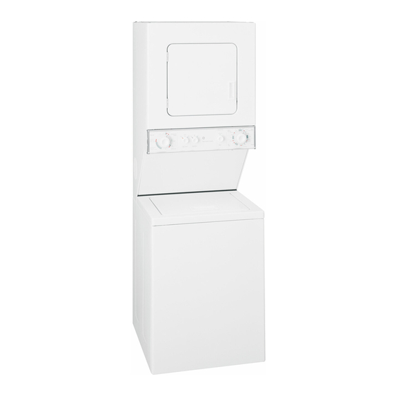
24"(61cm) electric washer/dryer
Hide thumbs
Also See for WSM2420:
- Use and care manual (28 pages) ,
- Installation instructions manual (16 pages) ,
- Dimensions (3 pages)
Advertisement
Quick Links
Download this manual
See also:
Use and Care Manual
WSM2420
24"(61CM) ELECTRIC WASHER/DRYER
INSTAILATION INSTRUCTIONS
Table of Contents
WASHER/DRYER SAFETY.............................. 1
INSTALLATIONINSTRUCTIONS....................2
Toolsand Par_s............................................. 2
Alternate Parts ............................................... 2
Location Requirements ................................ 2
Drain System................................................. 3
Electrical Requirements ................................ 4
Electrical Connection .................................... 5
Venting Requirements.................................10
Install Leveling Legs....................................11
Remove Foam Packing...............................11
Connect Drain Hose....................................11
Connect Inlet Hoses....................................12
Secure Drain Hose......................................13
Plan Vent System........................................13
Install Vent System......................................15
Level Washer/Dryer.....................................15
Connect Vent............................................... 1 5
Complete Installation..................................15
WASHER/DRYER SAFETY
Your safety and the safety of others are very important.
We have provided many important safety messages in this manual and on your appliance. Always read and obey all safety
messages.
This is the safety alert symbol.
This symbol alerts you to potential hazards that can kill or hurt you and others.
All safety messages will follow the safety alert symbol and either the word "DANGER" or "WARNING."
These words mean:
You can be killed or seriously injured if you don't immediately
follow
instructions.
You can be killed or seriously injured if you don't follow
instructions.
All safety messages will tell you what the potential hazard is, tell you how to reduce the chance of injury, and tell you what can
happen if the instructions are not followed.
8577192
Advertisement

Related Manuals for GE WSM2420


Summary of Contents for GE WSM2420
-
Page 1: Table Of Contents
WSM2420 24"(61CM) ELECTRIC WASHER/DRYER INSTAILATION INSTRUCTIONS Table of Contents WASHER/DRYER SAFETY......1 INSTALLATIONINSTRUCTIONS....2 Toolsand Par_s..........2 Alternate Parts ..........2 Location Requirements ........ 2 Drain System..........3 Electrical Requirements ........ 4 Electrical Connection ........5 Venting Requirements.........10 Install Leveling Legs........11 Remove Foam Packing.......11... -
Page 2: Installationinstructions
INSTALLATION INSTRUCTIONS Gather the required tools and parts before starting installation. Your installation may require additional parts. For ordering Read and follow the instructions provided with any tools listed information, please refer to the Use and Care Guide. here. If You Have You Will Need to Buy Tools needed:. -
Page 3: Alternate Parts
• Awater h eater settodeliver 120°F ( 49°C) water tothewasher. • Rear clearance may be 0" when house exhaust system is lined up directly with dryer exhaust. • Hotand coldwater faucets l ocated w ithin 4ft (1.2 m)ofthe hotandcold water fillvalves, and water pressure of5-100 psi (34.5-689.6 kPa). -
Page 4: Electrical Connection
A UL listed 30-amp power supply cord, rated 120/240 volt Floor drain system (view D) minimum. The cord should be type SRD or SRDT and be at The floor drain system requires a siphon break that may be least 4 ft (1.22 m) long. The wires that connect to the dryer purchased separately. - Page 5 Power Supply C ord Direct Wire Fire Hazard Fire Hazard Use a new UL listed 30 amp power supply cord. Use 10 gauge solid copper wire. Use a UL listed strain relief. Use a UL listed strain relief. Disconnect power before making electrical connections. Disconnect power before making electrical connections.
- Page 6 Put power supply cord through the strain relief. Be sure that Electrical Connection Options the wire insulation on the power supply cord is inside the If your home has: And you will be Go to Section strain relief. The strain relief should have a tight fit with the dryer cabinet and be in a horizontal position.
-
Page 7: Venting Requirements
Remove center, silver-colored terminal block screw. 4-wire connection: Direct Wire Remove neutral ground wire from internal ground conductor screw. Connect neutral ground wire and the neutral wire (white IMPORTANT: A 4-wire connection is required for mobile homes or center wire) of power supply cord under center, silver- and where local codes do not permit the use of 3-wire colored terminal block screw. - Page 8 Move the green painted screw from the internal to the external Loosen or remove center, silver-colored terminal block screw. ground location. Connect ground wire (green or bare) of power Connect neutral wire (white or center wire) of power supply supply cable to external ground conductor screw. Tighten cord to the center, silver-colored terminal screw of the terminal screw.
- Page 9 Loosen or remove center, silver-colored terminal block screw. Optional 3-wire connection Place the hooked end of the neutral wire (white or center wire) of direct wire cable under the center screw of terminal block Use for direct wire or power supply cord where local codes do (hook facing right).
- Page 10 Rigid metal vent • For best drying performance, rigid metal vents are recommended. • Rigid metal vent is recommended to avoid crushing and kinking. Flexible metal vent • Flexible metal vents are acceptable only if accessible for cleaning. Fire Hazard •...
- Page 11 The angled hood style (shown here) is acceptable. Install the front leveling legs 1. Examine the front leveling legs. Find the diamond marking. 4" 2. Screw front legs by hand, into the holes in the triangular braces in the front corners. Use wrench to finish turning the legs until the diamond marking is no longer visible.
- Page 12 Connect the inlet hoses to the water faucets 4. Open clamp. Twist hose back and forth while pushing onto drain connector on the side of the washer/dryer. Continue until Make sure the washer basket is empty. hose contacts the ribbed stops on the cabinet. 2.
- Page 13 If you are working in a closet or recessed area Move the washer/dryer into its final position and remove cardboard from under washer/dryer. Remove the access panel by removing three Phillips-head screws and one bumper, located at Choose your exhaust installation type the top of the access panel.
- Page 14 Alternate installations for close clearances Determine vent path Venting systems come in many varieties. Select the type best for your installation, Three close-clearance installations are shown. • Select the route that will provide the straightest and most Refer to the manufacturer's instructions provided with the vent direct path outdoors.
-
Page 15: Level Washer/Dryer
1. Install exhaust hood. Use caulking compound to seal exterior 1. Check that all parts are now installed. If there is an extra part, wall opening around exhaust hood. go back through the steps to see which step was skipped. 2. - Page 16 8577192 (c) 2005. 7/05 Printed in U.S.A. All rights reserved. Benton Harbor, Michigan 49022...