Table of Contents
Advertisement
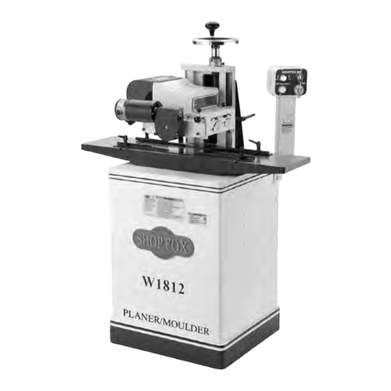
MODEL W1812
VARIABLE SPEED PLANER/
MOULDER WITH STAND
OWNER'S MANUAL
(FOR MODELS MANUFACTURED SINCE 01/12)
Phone: (360) 734-3482 • Online Technical Support: tech-support@shopfox.biz
COPYRIGHT © MARCH, 2009 BY WOODSTOCK INTERNATIONAL, INC. REVISED NOVEMBER, 2011 (KN)
WARNING: NO PORTION OF THIS MANUAL MAY BE REPRODUCED IN ANY SHAPE OR FORM WITHOUT
177335
THE WRITTEN APPROVAL OF WOODSTOCK INTERNATIONAL, INC.
#11399CR Printed in Taiwan
Advertisement
Table of Contents

Related Manuals for Shop fox W1812


Summary of Contents for Shop fox W1812
- Page 1 MODEL W1812 VARIABLE SPEED PLANER/ MOULDER WITH STAND OWNER'S MANUAL (FOR MODELS MANUFACTURED SINCE 01/12) Phone: (360) 734-3482 • Online Technical Support: tech-support@shopfox.biz COPYRIGHT © MARCH, 2009 BY WOODSTOCK INTERNATIONAL, INC. REVISED NOVEMBER, 2011 (KN) WARNING: NO PORTION OF THIS MANUAL MAY BE REPRODUCED IN ANY SHAPE OR FORM WITHOUT 177335 THE WRITTEN APPROVAL OF WOODSTOCK INTERNATIONAL, INC. #11399CR Printed in Taiwan...
- Page 2 This manual provides critical safety instructions on the proper setup, operation, maintenance, and service of this machine/tool. Save this document, refer to it often, and use it to instruct other operators. Failure to read, understand and follow the instructions in this manual may result in fire or serious personal injury—including amputation, electrocution, or death.
-
Page 3: Table Of Contents
Contents INTRODUCTION ........2 ACCESSORIES ........31 Woodstock Technical Support ....2 MAINTENANCE ........33 Controls & Features ......2 General .......... 33 Machine Specifications ......3 Cleaning ......... 33 SAFETY ..........5 Cleaning Feed Motor ......33 Standard Machinery Safety Instructions ..5 Table &... -
Page 4: Introduction
W1812 Owner's Manual (Mfg. Since 12/10) INTRODUCTION Woodstock Technical Support This machine has been specially designed to provide many years of trouble-free service. Close attention to detail, ruggedly built parts and a rigid quality control program assure safe and reliable operation. -
Page 5: Machine Specifications
⁄ Voltage, Amps ..................... 180VDC, 1.2A Motor Speed ............... 0-55 RPM (w/(Voltage Reduction) Feed Speed ......................0-18 FPM Cycle ......................... 60 Hz Number Of Speeds ..................Variable Speed Power Transfer ....................Chain Drive Main Specifications Model W1812 Machine Specifications, Page 1 of 2... - Page 6 Heavy-Duty Cast Iron Handwheel with Inch Measurement Scale for Cutterhead Housing Lift Precision-Ground Cast Iron Infeed and Outfeed Extension Wings Dovetailed Way for Cutterhead Housing with Precision Gib Adjustments Pedestal-Mounted Control Switch with Variable Speed Control Model W1812 Machine Specifications, Page 2 of 2...
-
Page 7: Safety
W1812 Owner's Manual (Mfg. Since 12/10) SAFETY SAFETY For Your Own Safety, Read Manual Before Operating Machine The purpose of safety symbols is to attract your attention to possible hazardous conditions. This manual uses a series of symbols and signal words intended to convey the level of importance of the safety messages. - Page 8 W1812 Owner's Manual (Mfg. Since 12/10) APPROVED OPERATION. Untrained operators STABLE MACHINE. Unexpected movement during can be seriously hurt by machinery. Only operations greatly increases the risk of injury allow trained or properly supervised people and loss of control. Verify machines are to use machine.
-
Page 9: Additional Safety For Planer/Moulders
W1812 Owner's Manual (Mfg. Since 12/10) Additional Safety for Planer/Moulders READ and understand this USE this and other machinery with caution entire manual before using and respect. Always consider safety first, this machine. Serious per- as it applies to your individual working sonal injury may occur conditions. -
Page 10: Electrical
W1812 Owner's Manual (Mfg. Since 12/10) ELECTRICAL Circuit Requirements This machine must be connected to the correct size and The machine must be properly set up type of power supply circuit, or fire or electrical damage before it is safe to operate. DO NOT may occur. -
Page 11: Grounding Requirements
W1812 Owner's Manual (Mfg. Since 12/10) Grounding Requirements This machine MUST be grounded. In the event of certain The machine must be properly set up types of malfunctions or breakdowns, grounding provides before it is safe to operate. DO NOT a path of least resistance for electric current to travel—in... -
Page 12: Setup
Shop Fox dealer immediately. Inventory The following is a description of the main components shipped with the Model W1812. Lay the components out Keep machine disconnected from to inventory them. power until instructed otherwise. -
Page 13: Machine Placement
W1812 Owner's Manual (Mfg. Since 12/10) Machine Placement Cleaning Machine • Floor Load: This machine distributes a The table and other unpainted parts of your heavy load in a small footprint. Some planer/moulder are coated with a waxy grease that protects them from corrosion during residential floors may require additional shipment. -
Page 14: Lifting & Moving
W1812 Owner's Manual (Mfg. Since 12/10) Lifting & Moving The Model W1812 can be moved short distances if two people lift the ends of the cast iron extension wings and walk the machine to the new location. For ease of mobility, the machine can be placed on a Shop Fox Model D2057A Heavy Duty Mobile Base. -
Page 15: Assembly
W1812 Owner's Manual (Mfg. Since 12/10) Assembly The Model W1812 Planer/Moulder is shipped with an off-the-shelf 48" Power Twist™ Link V-Belt. The planer/ moulder is designed for a 45" V-belt, so the included V-belt must be modified before installing it. - Page 16 W1812 Owner's Manual (Mfg. Since 12/10) Position the stand upright, adjust the feet so the stand sits level on the floor, then tighten the lock nuts to lock the feet in place. Brace Shipping 4. Remove the rear panel, then secure the headstock to...
- Page 17 W1812 Owner's Manual (Mfg. Since 12/10) 11. Feed the control panel wiring harnesses through the hole in the stand, and secure the pedestal control panel to the stand, as shown in Figure 14, using three ⁄ "-18 x 1" hex bolts and ⁄...
-
Page 18: Dust Collection
W1812 Owner's Manual (Mfg. Since 12/10) 19. Install the dust hood (see Figure 17) with three #10- Dust 24 x ⁄ " flange screws. Hood 20. Install a 4" flexible hose to the dust port, as shown in Figure 17. -
Page 19: Test Run
W1812 Owner's Manual (Mfg. Since 12/10) Test Run Once the assembly is complete, test run your machine to make sure it runs properly and is ready for regular operation. The test run consists of verifying the following: 1) The motor powers up and runs correctly, and 2) the safety disabling mechanisms work correctly. -
Page 20: Operations
W1812 Owner's Manual (Mfg. Since 12/10) OPERATIONS General This machine will perform many types of operations that are beyond the scope of this manual. Many of these operations can be dangerous or deadly if performed incorrectly. The instructions in this section are written with the understanding that the operator has the necessary knowledge and skills to operate this machine. -
Page 21: Installing Planing Knives
W1812 Owner's Manual (Mfg. Since 12/10) Installing Planing Knives Chip Deflector WEAR thick gloves extreme caution when working near cutting surfaces. Planing knives are dangerously sharp! Failure to exercise care while working near knives could result in severe injury. To install the planing knives, do these steps: DISCONNECT MACHINE FROM POWER! Figure 22. -
Page 22: Installing Moulding Knives
W1812 Owner's Manual (Mfg. Since 12/10) Installing Moulding Knives Chip Moulding knives have many different profiles. Before Deflector starting the machine, always verify that the mould- ing knives do not contact any part of the workpiece guide rails, feed roller swing arm, or the table sur- face. -
Page 23: Feed Roller Height & Spring Tension
W1812 Owner's Manual (Mfg. Since 12/10) Feed Roller Height & Spring Tension After switching between planing and molding operations, you must re-adjust the feed roller height and spring tension, so the workpiece is drawn through the planer/ moulder without chatter or slip. Rollers that are too high, or have light spring tension can cause workpiece chatter or slip. - Page 24 W1812 Owner's Manual (Mfg. Since 12/10) —If a certain moulding knife profile does not allow you to adjust the outfeed roller down far enough for proper roller traction, the eccentric stop must be repositioned to the lower hole. To do this,...
-
Page 25: Workpiece Inspection
W1812 Owner's Manual (Mfg. Since 12/10) Workpiece Inspection Before using this planer/moulder, inspect each and every workpiece for the following problems, and be familiar with the hardness of the wood. • Each workpiece must have at least one flat surface to slide along the planer/moulder table. -
Page 26: Planing Do's & Don'ts
W1812 Owner's Manual (Mfg. Since 12/10) Planing Do's & Don'ts There are common mistakes that must be avoided when planing. CORRECT Multiple Boards Only plane one board at a time (see figure 35). Whether you use guide rails or not, never attempt to plane more than one board at a time side-by-side. -
Page 27: Planing Operation
W1812 Owner's Manual (Mfg. Since 12/10) Planing Operation The maximum cutting depth for soft wood at full cutterhead width is no more than ⁄ " deep; however, keep in mind that the harder the wood, the shallower the cutting depth and the slower the feed rate should be. A... -
Page 28: Moulding Do's & Don'ts
W1812 Owner's Manual (Mfg. Since 12/10) Moulding Do's & Don'ts The Model W1812 will accommodate most moulding knife profiles. However, you must still pay special attention to CORRECT workpiece support and knife-to-table clearance. Refer to the following examples to avoid common workpiece setup mistakes. - Page 29 W1812 Owner's Manual (Mfg. Since 12/10) Crown Moulding Support When cutting crown moulding (see figure 39), make a wooden V-track that can be clamped to the table. The CORRECT V-track must support at least 50% of the workpiece height on both sides.
- Page 30 W1812 Owner's Manual (Mfg. Since 12/10) Size Workpiece Appropriately Make sure to cut your workpiece to the correct width for the knife being used (see figure 41). To improve knife life CORRECT and workpiece results when cutting in very hard woods, use a table saw to rabbet out some of the profile before running the workpiece through the planer/moulder.
- Page 31 W1812 Owner's Manual (Mfg. Since 12/10) Edge Moulding Tall Workpieces When cutting edge profiles on workpieces that are taller than they are wide, you must clamp wooden extension rails to the table so they support at least 75% of the workpiece height on both sides (see figure 43).
-
Page 32: Moulding Operation
W1812 Owner's Manual (Mfg. Since 12/10) Moulding Operation The maximum depth of a moulding cut in soft wood is ⁄ ". For hard or knotty wood the maximum depth of cut must be less, and the feed rate may have to be reduced. -
Page 33: Accessories
Using the existing guide rail mounting hardware from the W1812 planer/moulder, this jig easily fastens to the planer/moulder table. The jig hand crank feeds arched wood into the cutterhead to create extreme- ly high quality casings and mouldings that match any pre- viously cut straight mouldings with the same profile. - Page 34 W1812 Owner's Manual (Mfg. Since 12/10) W1727—1 HP Dust Collector A perfect dedicated dust collector for a planer/moulder on a job site or in a shop. The motor is 1HP, 110V/220V, single-phase; and the flow specifications are 800 CFM with a static pressure of 5.67"...
-
Page 35: Maintenance
W1812 Owner's Manual (Mfg. Since 12/10) MAINTENANCE General Regular maintenance on your machine will ensure its optimum performance. Make a habit of inspecting your machine each time you use it. • Loose mounting bolts. • Worn switch, damaged cords, and plugs. -
Page 36: Lubrication
W1812 Owner's Manual (Mfg. Since 12/10) Lubrication figures 51—53 show lubrication locations that need attention every six months; however, under heavy use or One of Four adverse working conditions, increase lubrication intervals Tensioner accordingly. Assemblies Since all bearings are sealed and permanently lubricated, simply leave them alone until they need to be replaced. -
Page 37: Service
W1812 Owner's Manual (Mfg. Since 12/10) SERVICE General This section covers the most common service adjustments or procedures that may need to be made during the life of your machine. If you require additional machine service information not included in this section, please contact Woodstock International Technical Support at (360) 734-3482 or send an e-mail to: tech-support@shopfox.biz. -
Page 38: Feed Roller-To-Table Alignment
W1812 Owner's Manual (Mfg. Since 12/10) Feed Roller-to-Table Alignment The feed rollers must be aligned correctly with the table to maintain a smooth and straight feed. 45° To check the feed roller-to-table alignment, do these steps: DISCONNECT MACHINE FROM POWER! 2. -
Page 39: Drive Chain Adjustment
W1812 Owner's Manual (Mfg. Since 12/10) Drive Chain Adjustment After long-term machine use, the rubber pad on the end Chain Tensioner of the drive chain tensioner (see figure 59) will wear. Rubber Pad The result is that the drive chain will become overly slack and can jump its sprockets, causing damage. -
Page 40: Gib Adjustment
W1812 Owner's Manual (Mfg. Since 12/10) Gib Adjustment Due to normal wear, the headstock gib will eventually have to be re-adjusted to remove any play in the ways. to adjust the headstock gib, do these steps: 1. DISCONNECT MACHINE FROM POWER! Column 2. -
Page 41: Electrical Safety Instructions
W1812 Owner's Manual (Mfg. Since 12/10) Electrical Safety Instructions These pages are current at the time of printing. However, in the spirit of improvement, we may make changes to the electrical systems of future machines. Study this diagram carefully. If you notice differences between your machine and these wiring diagrams, call Woodstock International Technical Support at (360) 734-3482. -
Page 42: Wiring Diagram
W1812 Owner's Manual (Mfg. Since 12/10) Wiring Diagram Read Page 39 STOP Before Wiring Diagram Wiring Ground 6-15 Plug WARNING ACCIDENTAL INJURY HAZARD! Disconnect power supply before adjustments, setup, 230 VAC or maintenance! Control Box Control Panel Keyed Power Console Unit... -
Page 43: Electrical Component Locations
W1812 Owner's Manual (Mfg. Since 12/10) Electrical Component Locations Read Page 39 STOP Before Wiring Feed Speed Dial Control Panel Keyed Power Feed Motor Switch ON Switch Feed Motor OFF Switch Circuit Board Start Capacitor Magnetic Contactor Motor Junction Box... -
Page 44: Troubleshooting
W1812 Owner's Manual (Mfg. Since 12/10) Troubleshooting This section covers the most common problems and corrections with this type of machine. WARNING! DO NOT make any adjustments until power is disconnected and moving parts have come to a complete stop! - Page 45 W1812 Owner's Manual (Mfg. Since 12/10) PROBLEM POSSIBLE CAUSE CORRECTIVE ACTION Machine has excessive 1. Motor fan rubbing on fan cover. 1. Fix/replace fan cover; replace loose or damaged vibration or noise. fan. 2. Machine incorrectly mounted on 2. Level/shim base; tighten/adjust mounting hardware floor or mobile base.
- Page 46 W1812 Owner's Manual (Mfg. Since 12/10) PROBLEM POSSIBLE CAUSE CORRECTIVE ACTION Excessive snipe (there is 1. One or both of the feed rollers are 1. Adjust the feed rollers to the correct height (Page a dip in the end of the set too low.
-
Page 47: Parts
W1812 Owner's Manual (Mfg. Since 12/10) PARTS Headstock 11V2 30V2 95V2 23V2 25V2 41V2 25V2 23V2 27V2 -45-... -
Page 48: Headstock Parts List
W1812 Owner's Manual (Mfg. Since 12/10) Headstock Parts List PART # DESCRIPTION PART # DESCRIPTION XPS07M PHLP HD SCR M4-.7 X 8 X1812039 SWING ARM AXIS SCREW XPN06 HEX NUT 1/2-12 X1812040 DRIVEN AXLE XPN05 HEX NUT 1/4-20 41V2 X1812041V2 HEAD CASTING V2.11.11... -
Page 49: Main Motor & Cabinet
W1812 Owner's Manual (Mfg. Since 12/10) Main Motor & Cabinet 213-4 213-1 229V2 216-1 213-2 213-3 217-1 217-3 216-1 217-4 217-2 PART # DESCRIPTION PART # DESCRIPTION XPSS02 SET SCREW 5/16-18 X 3/8 217-2 X1812217-2 OL RELAY SDE RA-20 12-18A... -
Page 50: Feed Motor & Controls
W1812 Owner's Manual (Mfg. Since 12/10) Feed Motor & Controls 302-1V2 302-3 302-2 302-4 303V2 326V2 376V2 315V2 315-2V2 315-1V2 310-1 379V2 342-1 305V2 368V2 Note: For wiring harness locations, refer to wiring diagram on Page 40. -48-... -
Page 51: Feed Motor & Controls Parts List
W1812 Owner's Manual (Mfg. Since 12/10) Feed Motor & Controls Parts List PART # DESCRIPTION PART # DESCRIPTION X1812086 SAFETY GUARD X1812352 CHAIN COVER X1812301 FEED ROLL SPROCKET X1812353 INFEED ROLLER DRIVE CHAIN X1812302 FEED MOTOR 1/8 HP 220V X1812354 OUTFEED ROLLER DRIVE CHAIN 302-1V2 X1812302-1V2 FEED MOTOR POWER CORD 18G 2C V2.12.10... -
Page 52: Label Placement
W1812 Owner's Manual (Mfg. Since 12/10) Label Placement Safety labels warn about machine hazards and how to prevent machine damage or injury. The owner of this machine MUST maintain the original location and readability of all labels on this machine. If any label is removed or becomes unreadable, REPLACE that label before allowing the machine to enter service again. - Page 53 W1812 Owner's Manual (Mfg. Since 12/10) Warranty Registration Name ___________________________________________________________________________________ Street __________________________________________________________________________________ City _________________________ State ___________________________Zip ________________________ Phone # ______________________ Email___________________________Invoice # ___________________ Model #_________Serial #______________Dealer Name__________________Purchase Date___________ The following information is given on a voluntary basis. It will be used for marketing purposes to help us develop better products and services.
- Page 54 FOLD ALONG DOTTED LINE Place Stamp Here WOODSTOCK INTERNATIONAL INC. P.O. BOx 2309 BELLINGHAM, WA 98227-2309 FOLD ALONG DOTTED LINE TAPE ALONG EDGES--PLEASE DO NOT STAPLE...
-
Page 55: Warranty
WARRANTY WARRANTY Woodstock International, Inc. warrants all Shop Fox machinery to be free of defects from workmanship and materials for a period of two years from the date of original purchase by the original owner. This warranty does not apply to defects due directly or indirectly to misuse, abuse, negligence or accidents, lack of maintenance, or reimbursement of third party expenses incurred. - Page 56 High Quality Machines and Tools Woodstock International, Inc. carries thousands of products designed to meet the needs of today's woodworkers and metalworkers. Ask your dealer about these fine products:...