Asus P5B-VM Manual
Hide thumbs
Also See for P5B-VM:
- Guide d'installation (102 pages) ,
- User manual (102 pages) ,
- User manual (156 pages)
Table of Contents
Advertisement
Advertisement
Table of Contents

Related Manuals for Asus P5B-VM


Summary of Contents for Asus P5B-VM
- Page 1 P5B-VM...
- Page 2 Product warranty or service will not be extended if: (1) the product is repaired, modified or altered, unless such repair, modification of alteration is authorized in writing by ASUS; or (2) the serial number of the product is defaced or missing.
-
Page 3: Table Of Contents
Contents Notices ......................vi Safety information ..................vii P5B-VM specifications summary ............... x Chapter 1: Product introduction Welcome! ..................1-2 Package contents ................. 1-2 Special features ................1-2 1.3.1 Product highlights ............1-4 1.3.2 Innovative ASUS features ..........1-4 Before you proceed ..............1-6 Motherboard overview .............. - Page 4 Chapter 2: BIOS setup Managing and updating your BIOS ..........2-2 2.1.1 Creating a bootable floppy disk ........2-2 2.1.2 ASUS EZ Flash 2 utility ........... 2-3 2.1.3 AFUDOS utility ..............2-4 2.1.4 ASUS CrashFree BIOS 3 utility ........2-6 2.1.5...
- Page 5 Support CD information .............. 3-2 3.2.1 Running the support CD ..........3-2 3.2.2 Drivers menu ..............3-3 3.2.3 Utilities menu ..............3-4 3.2.4 Make disk menu .............. 3-5 3.2.5 Manual ................3-6 3.2.6 ASUS Contact information ..........3-6 Software information ..............3-7...
-
Page 6: Notices
Notices Federal Communications Commission Statement This device complies with Part 15 of the FCC Rules. Operation is subject to the following two conditions: • This device may not cause harmful interference, and • This device must accept any interference received including interference that may cause undesired operation. -
Page 7: Safety Information
Safety information Electrical safety • To prevent electrical shock hazard, disconnect the power cable from the electrical outlet before relocating the system. • When adding or removing devices to or from the system, ensure that the power cables for the devices are unplugged before the signal cables are connected. -
Page 8: About This Guide
Refer to the following sources for additional information and for product and software updates. ASUS websites The ASUS website provides updated information on ASUS hardware and software products. Refer to the ASUS contact information. Optional documentation Your product package may include optional documentation, such as warranty flyers, that may have been added by your dealer. -
Page 9: Conventions Used In This Guide
Conventions used in this guide To make sure that you perform certain tasks properly, take note of the following symbols used throughout this manual. DANGER/WARNING: Information to prevent injury to yourself when trying to complete a task. CAUTION: Information to prevent damage to the components when trying to complete a task. -
Page 10: P5B-Vm Specifications Summary
® Celeron D Processors ® Compatible with Intel 05B/05A/06 processors ® Intel Hyper-Threading Technology ready ® Refer to www.asus.com for Intel CPU support list Chipset Northbridge: Intel G965 with Intel Clear Video Technology ® ® Southbridge: Intel ICH8 ® System Bus... - Page 11 System panel connector BIOS features 8 Mb Flash ROM, AMI BIOS, PnP, DMI 2.0, WfM2.0, SM BIOS 2.3, ACPI 2.0a, ASUS EZ Flash 2, ASUS CrashFree BIOS 3 Manageability WfM 2.0, DMI 2.0, WOL by PME, WOR by PME, PXE...
-
Page 13: Chapter 1: Product Introduction
This chapter describes the motherboard features and the new technologies it supports. Product introduction... -
Page 14: Welcome
Green ASUS This motherboard and its packaging comply with the European Union’s Restriction on the use of Hazardous Substances (RoHS). This is in line with the ASUS vision of creating environment-friendly and recyclable products/packaging to safeguard consumers’ health while minimizing the impact on the environment. - Page 15 S/PDIF digital sound ready The motherboard supports the S/PDIF-out (SONY-PHILIPS Digtal Interface) function through the S/PDIF interface at mid-board. It allows to transfer digital audio without converting to analog format and keeps the best signal quality. See pages 1-30 for details. ASUS P5B-VM...
-
Page 16: High Definition Audio
ASUS Advanced Q-Fan The ASUS advanced Q-Fan technology on P5B Series is powered by Intel Quiet System Technology; It makes the change of fan speed more smoothly. It’s better in fan use, and efficiently reduces the noise caused by fans’ abruptly speeding up. -
Page 17: Asus Special Features
See page 1-39 for details. ASUS CrashFree BIOS 3 The ASUS CrashFree BIOS 3 allows users to restore corrupted BIOS data from a USB flash disk containing the BIOS file. See page 2-6 for details. ASUS EZ Flash 2 EZ Flash 2 is a user-friendly BIOS update utility. -
Page 18: Before You Proceed
The illustration below shows the location of the onboard LED. SB_PWR Standby Powered Power P5B-VM Onboard LED Chapter 1: Product introduction... -
Page 19: Motherboard Overview
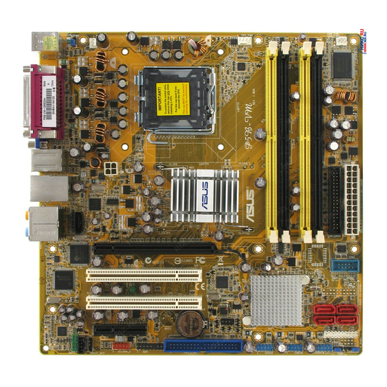
Screw holes Place eight (8) screws into the holes indicated by circles to secure the motherboard to the chassis. Do not overtighten the screws! Doing so can damage the motherboard. Place this side towards the rear of the chassis ASUS P5B-VM... - Page 20 1.5.3 Motherboard layout 24.5cm (9.6in) CHA_FAN1 PS/2KBMS T : Mouse CPU_FAN B: Keyboard Super I/O ESATA LGA775 1394_USB12 ATX12V LAN_USB34 Intel G965MCH RTL8111B AUDIO PCIEX16 JMicron JMB363 PCI1 COM1 TSB43AB22A SB_PWR Intel ICH8 PCI2 SATA2 SATA1 CR2032 3V 8Mb BIOS Lithium Cell SATA4 SATA3...
-
Page 21: Layout Contents
Line Out port (lime) 1-28 10. Microphone port (pink) 1-28 11. Side Speaker Out port (gray) 1-28 12. USB 2.0 ports 3 and 4 1-29 13. External SATA port 1-29 14. IEEE 1394a port 1-28 15. PS/2 keyboard port (purple) 1-29 ASUS P5B-VM... - Page 22 Internal connectors Page Floppy disk drive connector (34-1 pin FLOPPY) 1-30 2. Digital Audio connector (4-1 pin SPDIF_OUT) 1-30 IDE connector (40-1 pin PRI_IDE) 1-31 ICH8 Serial ATA connectors (7-pin SATA1, SATA2,SATA3, SATA4) 1-32 ® JMicron JMB363 Serial ATA RAID connector (7-pin SATA_RAID) 1-33 IEEE 1394a port connector (10-1 pin IE1394_2) 1-33...
-
Page 23: Central Processing Unit (Cpu)
ASUS will shoulder the cost of repair only if the damage is shipment/transit-related. • Keep the cap after installing the motherboard. ASUS will process Return Merchandise Authorization (RMA) requests only if the motherboard comes with the cap on the LGA775 socket. -
Page 24: Installing The Cpu
Installing the CPU To install a CPU: Locate the CPU socket on the motherboard. P5B-VM CPU Socket 775 Before installing the CPU, make sure that the cam box is facing towards you and the load lever is on your left. - Page 25 ® ® The motherboard supports Intel LGA775 processors with the Intel Enhanced ® Memory 64 Technology (EM64T), Enhanced Intel SpeedStep Technology (EIST), and Hyper-Threading Technology. Refer to the Appendix for more information on these CPU features. ASUS P5B-VM 1-13...
-
Page 26: Installing The Cpu Heatsink And Fan
1.6.2 Installing the CPU heatsink and fan ® The Intel LGA775 processor requires a specially designed heatsink and fan assembly to ensure optimum thermal condition and performance. ® • When you buy a boxed Intel processor, the package includes the CPU fan and heatsink assembly. - Page 27 Connect the CPU fan cable to the connector on the motherboard labeled CPU_FAN. CPU_FAN P5B-VM CPU Fan Connector Do not forget to connect the CPU fan connector! Hardware monitoring errors can occur if you fail to plug this connector. ASUS P5B-VM...
-
Page 28: Uninstalling The Cpu Heatsink And Fan
1.6.3 Uninstalling the CPU heatsink and fan To uninstall the CPU heatsink and fan: Disconnect the CPU fan cable from the connector on the motherboard. Rotate each fastener counterclockwise. Pull up two fasteners at a time in a diagonal sequence to disengage the heatsink and fan assembly from the motherboard. - Page 29 The narrow end of the groove should point outward after resetting. (The photo shows the groove shaded for emphasis.) Refer to the documentation in the boxed or stand-alone CPU fan package for detailed information on CPU fan installation. ASUS P5B-VM 1-17...
-
Page 30: System Memory
System memory 1.7.1 Overview The motherboard comes with four Double Data Rate 2 (DDR2) Dual Inline Memory Modules (DIMM) sockets. A DDR2 module has the same physical dimensions as a DDR DIMM but has a 240-pin footprint compared to the 184-pin DDR DIMM. DDR2 DIMMs are notched differently to prevent installation on a DDR DIMM socket. - Page 31 DDR2-533 by default setting. If you want to operate with lower latency, adjust the memory timing manually. There will be 8MB reduction in total memory when enabling ASUS Thermostat function under Single Channel mode, and 16MB reduction under Dual Channel Mode.
- Page 32 Qualified Vendors Lists (QVL) DDR2 800 DIMM support Size Vendor Chip No. Side(s) Part No. 512MB KINGSTON K4T51083QC KVR800D2N5/512 • • • 1024MB KINGSTON K4T51083QC KVR800D2N5/1G • • 512MB Qimonda HYB18T256800AF25F HYS64T64020HU-25F-A • • 256MB Qimonda HYB18T512160BF-25F HYS64T32000HU-25F-B • • 512MB Qimonda HYB18T512800BF25F...
- Page 33 KINGMAX 5MB22D9DCN KLBD48F-A8ME4 • Visit the ASUS website (www.asus.com) for the latest QVL. Side(s): SS - Single-sided DS - Double-sided DIMM support: Supports one module inserted into any slot as Single-channel memory configuration. Supports one pair of modules inserted into either the blue slots or the black slots as one pair of Dual-channel memory configuration.
-
Page 34: Installing A Dimm
1.7.3 Installing a DIMM Unplug the power supply before adding or removing DIMMs or other system components. Failure to do so can cause severe damage to both the motherboard and the components. To install a DIMM: DDR2 DIMM notch Unlock a DIMM socket by pressing the retaining clips outward. -
Page 35: Expansion Slots
IRQ” or that the cards do not need IRQ assignments. Otherwise, conflicts will arise between the two PCI groups, making the system unstable and the card inoperable. Refer to the table on the next page for details. ASUS P5B-VM 1-23... -
Page 36: Interrupt Assignments
1.8.3 Interrupt assignments Standard interrupt assignments Priority Standard Function System Timer Keyboard Controller — Re-direct to IRQ#9 IRQ holder for PCI steering* Communications Port (COM1)* IRQ holder for PCI steering* Floppy Disk Controller Printer Port (LPT1)* System CMOS/Real Time Clock ACPI* SMBus Controller* IRQ holder for PCI steering*... -
Page 37: Pci Slots
PCI Express x4 slot. 2.5.6 PCI Express x16 slot This motherboard supports PCI Express x16 graphic cards that comply with the PCI Express specifications. The figure shows a graphics card installed on the PCI Express x16 sloti ASUS P5B-VM 1-25... -
Page 38: Jumpers
CLRTC Normal Clear CMOS (Default) P5B-VM Clear RTC RAM • You do not need to clear the RTC when the system hangs due to overclocking. For system failure due to overclocking, use the C.P.R. (CPU Parameter Recall) feature. Shut down and reboot the system so the BIOS can automatically reset parameter settings to default values. - Page 39 (the default is the Space Bar). This feature requires an ATX power supply that can supply at least 1A on the +5VSB lead, and a corresponding setting in the BIOS. KBPWR +5VSB (Default) P5B-VM Keyboard Power Setting ASUS P5B-VM 1-27...
-
Page 40: 1.10 Connectors
1.10 Connectors 1.10.1 Rear panel connectors PS/2 mouse port (green). This port is for a PS/2 mouse. Parallel port. This 25-pin port connects a parallel printer, a scanner, or other devices. IEEE 1394a port. This 6-pin IEEE 1394a port provides high-speed connectivity for audio/video devices, storage peripherals, PCs, or portable devices. - Page 41 DO NOT insert a different connector to this port. • DO NOT unplug the external Serial ATA box when a RAID 0 or JBOD is configured. 15. PS/2 keyboard port (purple). This port is for a PS/2 keyboard. ASUS P5B-VM 1-29...
-
Page 42: Internal Connectors
This connector is for the S/PDIF audio module to allow digital sound output. Connect one end of the S/PDIF audio cable to this connector and the other end to the S/PDIF module. SPDIFOUT SPDIF_OUT P5B-VM Digital Audio Connector The S/PDIF out module is purchased separately. 1-30 Chapter 1: Product introduction... -
Page 43: Ide Connectors
If any device jumper is set as “Cable-Select,” make sure all other device jumpers have the same setting. PRI_EIDE PIN1 NOTE: Orient the red markings (usually zigzag) on the ID ribbon cable to PIN 1. P5B-VM IDE Connector ASUS P5B-VM 1-31... - Page 44 SATA1 SATA2 SATA3 SATA4 P5B-VM SATA Connectors When using the connectors in Standard IDE mode, connect the primary (boot) hard disk drive to the SATA1/2 connector. Refer to the table below for the recommended SATA hard disk drive connections. right angle side...
- Page 45 RSATA _RXP1 RSATA _TXN1 RSATA _TXP1 P5B-VM SATA RAID Connector Before creating a RAID set using Serial ATA hard disks, make sure that you have connected the Serial ATA signal cables and installed Serial ATA hard disk drives; otherwise, you cannot enter the JMicron JMB363 RAID utility and SATA ®...
- Page 46 Never connect a 1394 cable to the USB connectors. Doing so will damage the motherboard! You can connect the USB cable to ASUS Q-Connector (USB, blue) first, and then install the Q-Connector (USB) to the USB connector onboard. The USB module is purchased separately.
- Page 47 Rotation CPU_FAN PWR_FAN P5B-VM Fan Connectors Only the CPU-FAN and CHA-FAN connectors support the ASUS Thermostat feature. Serial port connector (10-1 pin COM1) This connector is for a serial (COM) port. Connect the serial port module cable to this connector, then install the module to a slot opening at the back of the system chassis.
- Page 48 MIC2_R AGND MIC2_L AGND MIC2_L P5B-VM Front Panel Audio Connector • We recommend that you connect a high-definition front panel audio module to this connector to avail of the motherboard’s high-definition audio capability. • By default, this connector is set to HD Audio. If you want to connect a AC’...
- Page 49 +5V Standby +5 Volts Power OK -5 Volts Ground Ground +5 Volts Ground Ground Ground P5B-VM ATX Power Connector +5 Volts PSON# Ground Ground +3 Volts -12 Volts +3 Volts +3 Volts • For a fully configured system, we recommend that you use a power supply unit (PSU) that complies with ATX 12 V Specification 2.0 (or later version)
-
Page 50: System Panel Connector
IDE_LED PWRSW Requires an ATX power supply System Panel Connector P5B-VM • System power LED (2-pin PLED) This 2-pin connector is for the system power LED. Connect the chassis power LED cable to this connector. The system power LED lights up when you turn on the system power, and blinks when the system is in sleep mode. - Page 51 Q-Connector (system panel) You can use ASUS Q-Connector to connect / disconnect chassis front panel cables by only a few steps. Directions below shows how to install ASUS Q- Connector. Step1. Connect correct front panel to ASUS Q- Connector first. You can refer to the marking on Q-Connector itself to know the detail pin definition.
-
Page 52: Chapter 2: Bios Setup
This chapter tells how to change the system settings through the BIOS Setup menus. Detailed descriptions of the BIOS parameters are also provided. BIOS setup... -
Page 53: Managing And Updating Your Bios
The following utilities allow you to manage and update the motherboard Basic Input/Output System (BIOS) setup. ASUS EZ Flash 2 (Updates the BIOS using a floppy disk, USB Flash, or the motherboard support CD during POST.) ASUS AFUDOS (Updates the BIOS in DOS mode using a bootable floppy disk.) -
Page 54: Asus Ez Flash 2 Utility
2.1.2 ASUS EZ Flash 2 utility The ASUS EZ Flash 2 feature allows you to update the BIOS without having to go through the long process of booting from a floppy disk and using a DOS-based utility. The EZ Flash 2 utility is built-in the BIOS chip so it is accessible by pressing <Alt>... -
Page 55: Afudos Utility
Extension name Press <Enter>. The utility copies the current BIOS file to the floppy disk. A:\>afudos /oOLDBIOS1.rom AMI Firmware Update Utility - Version 1.19(ASUS V2.07(03.11.24BB)) Copyright (C) 2002 American Megatrends, Inc. All rights reserved. Reading flash ..done Write to file..ok A:\>... - Page 56 Updating the BIOS file To update the BIOS file using the AFUDOS utility: Visit the ASUS website (www.asus.com) and download the latest BIOS file for the motherboard. Save the BIOS file to a bootable floppy disk. Write the BIOS filename on a piece of paper. You need to type the exact BIOS filename at the DOS prompt.
-
Page 57: Asus Crashfree Bios 3 Utility
2.1.4 ASUS CrashFree BIOS 3 utility The ASUS CrashFree BIOS 3 is an auto recovery tool that allows you to restore the BIOS file when it fails or gets corrupted during the updating process. You can update a corrupted BIOS file using the motherboard support CD, the USB flash disk, or the floppy disk that contains the updated BIOS file. - Page 58 BIOS file and starts flashing the corrupted BIOS file. Restart the system after the utility completes the updating process. The recovered BIOS may not be the latest BIOS version for this motherboard. Visit the ASUS website (www.asus.com) to download the latest BIOS file. ASUS P5B-VM...
-
Page 59: Asus Update Utility
DO NOT shut down or reset the system while updating the BIOS! Doing so can cause system boot failure! 2.1.5 ASUS Update utility The ASUS Update is a utility that allows you to manage, save, and update the motherboard BIOS in Windows environment. The ASUS Update utility allows you ®... - Page 60 To update the BIOS through the Internet: Launch the ASUS Update utility from the Windows desktop by clicking Start ® > Programs > ASUS > ASUSUpdate > ASUSUpdate. The ASUS Update main window appears. Select Update BIOS from Select the ASUS FTP site nearest...
- Page 61 To update the BIOS through a BIOS file: Launch the ASUS Update utility from the Windows desktop by clicking Start ® > Programs > ASUS > ASUSUpdate > ASUSUpdate. The ASUS Update main window appears. Select Update BIOS from a file option from the drop-down menu, then click Next.
-
Page 62: Bios Setup Program
The BIOS setup screens shown in this section are for reference purposes only, and may not exactly match what you see on your screen. • Visit the ASUS website (www.asus.com) to download the latest BIOS file for this motherboard. ASUS P5B-VM... -
Page 63: Bios Menu Screen
2.2.1 BIOS menu screen Menu items Menu bar Configuration fields General help Use [ENTER], [TAB] System Time [11:51:19] or [SHIFT-TAB] to System Date [Mon 05/15/2006] select a field. Legacy Diskette A [1.44M, 3.5 in] Use [+] or [-] to configure system time. SATA 1 :[Not Detected SATA 2... -
Page 64: Menu Items
[Enabled] Change Option General Help MPS Revision [1.4] screen. Save and Exit Exit 2.2.9 General help Pop-up window At the top right corner of the menu screen is Scroll bar a brief description of the selected item. ASUS P5B-VM 2-13... -
Page 65: Main Menu
Main menu When you enter the BIOS Setup program, the Main menu screen appears, giving you an overview of the basic system information. Refer to section “4.2.1 BIOS menu screen” for information on the menu screen items and how to navigate through them. Use [ENTER], [TAB] System Time [11:51:19]... - Page 66 When set to [Disabled], the data transfer from and to the device occurs one sector at a time. Configuration options: [Disabled] [Auto] ASUS P5B-VM 2-15...
-
Page 67: Ide Configuration
PIO Mode [Auto] Selects the PIO mode. Configuration options: [Auto] [0] [1] [2] [3] [4] DMA Mode [Auto] Selects the DMA mode. Configuration options: [Auto] [SWDMA0] [SWDMA1] [SWDMA2] [MWDMA0] [MWDMA1] [MWDMA2] [UDMA0] [UDMA1] [UDMA2] [UDMA3] [UDMA4] [UDMA5] SMART Monitoring [Auto] Sets the Smart Monitoring, Analysis, and Reporting Technology. -
Page 68: System Information
Processor Type : Intel(R) Pentium(R) 4 CPU 3.00GHz Speed : 3000MHz Count System Memory Usable Size: 256MB AMI BIOS Displays the auto-detected BIOS information Processor Displays the auto-detected CPU specification System Memory Displays the auto-detected system memory ASUS P5B-VM 2-17... -
Page 69: Cpu Configuration
Advanced menu The Advanced menu items allow you to change the settings for the CPU and other system devices. Take caution when changing the settings of the Advanced menu items. Incorrect field values can cause the system to malfunction. Jumperfree Configuration USB Configuration CPU Configuration Chipset... - Page 70 CPU installed. Setting to Auto allows the BIOS to detect the VCore voltage of the CPU installed. Refer to the CPU documentation before setting the CPU VCore voltage. A very high Vcore voltage can severely damage the CPU! ASUS P5B-VM 2-19...
-
Page 71: Usb Configuration
2.4.2 USB Configuration The items in this menu allows you to change the USB-related features. Select an item then press <Enter> to display the configuration options. USB Configuration Module Version - 2.24.0-11.4 USB Devices Enabled: None Legacy USB Support [Auto] Port 64/60 Emulation [Disabled] USB 2.0 Controller Mode... -
Page 72: Cpu Configuration
CPU power consumption is reduced. Configuration options: [Disabled] [Enabled] Execute Disable Function [Enabled] Allows you to Enable/disable Execute Disable Function. Configuration options: [Disabled] [Enabled] Hyper-Threading Technology [Enabled] Allows you to enable or disable the processor Hyper-Threading Technology. Configuration options: [Disabled] [Enabled] ASUS P5B-VM 2-21... -
Page 73: Chipset
The following item appears only when you installed an Intel Pentium 4 or ® ® later CPU that supports the Enhanced Intel SpeedStep Technology (EIST). ® Intel(R) SpeedStep Technology [Automatic] Allows you to use the Enhanced Intel SpeedStep Technology. When set to ®... - Page 74 Allows you to select the fixed graphic memory size. Configuration options: [0MB] [32MB] [64MB] [128MB] DVMT Graphic Memory Size [128MB] Allows you to select the DVMT graphic memory size. Configuration options: [0MB] [32MB] [64MB] [128MB] [224MB] PEG Force x1 [Disabled] Configuration options: [Enabled] [Disabled] ASUS P5B-VM 2-23...
-
Page 75: Onboard Devices Configuration
2.4.5 Onboard Devices Configuration HD Audio Controller [Enabled] Onboard 1394 Controller [Enabled] Onboard PCIE GbE LAN [Enabled] LAN Option ROM [Disabled] JMicron SATA/PATA Controller [Enabled] JMicron Controller Mode [BASIC] Serial Port1 Address [3F8/IRQ4] Parallel Port Address [378] Parallel Port Mode [ECP] ECP Mode DMA Channel [DMA3]... - Page 76 ECP Mode DMA Channel [DMA3] Appears only when the Parallel Port Mode is set to [ECP]. This item allows you to set the Parallel Port ECP DMA. Configuration options: [DMA0] [DMA1] [DMA3] Parallel Port IRQ [IRQ7] Configuration options: [IRQ5] [IRQ7] ASUS P5B-VM 2-25...
-
Page 77: Pci Pnp
2.4.6 PCI PnP The PCI PnP menu items allow you to change the advanced settings for PCI/PnP devices. The menu includes setting IRQ and DMA channel resources for either PCI/PnP or legacy ISA devices, and setting the memory size block for legacy ISA devices. -
Page 78: Power Menu
Allows you to enable or disable the Advanced Configuration and Power Interface (ACPI) support in the Application-Specific Integrated Circuit (ASIC). When set to Enabled, the ACPI APIC table pointer is included in the RSDT pointer list. Configuration options: [Disabled] [Enabled] ASUS P5B-VM 2-27... -
Page 79: Apm Configuration
2.5.5 APM Configuration APM Configuration Restore on AC Power Loss [Power Off] Power On By RTC Alarm [Disabled] Power On By External Modems [Disabled] Power On By PCI Devices [Disabled] Power On By PCIE Devices [Disabled] Power On By PS/2 Keyboard [Disabled] Power On By PS/2 Mouse [Disabled]... -
Page 80: Hardware Monitor
3.3V Voltage [ 3.345V] 5V Voltage [ 5.094V] 12V Voltage [11.880V] ASUS Advanced Q-Fan Control Fan Profile [Silent] CPU Temperature [xxxºC/xxxºF] MB Temperature [xxxºC/xxxºF] The onboard hardware monitor automatically detects and displays the motherboard and CPU temperatures. Select Ignored if you do not wish to display the detected temperatures. -
Page 81: Boot Menu
The onboard hardware monitor automatically detects the voltage output through the onboard voltage regulators. ASUS Advanced Q-Fan Control [Disabled] Allows you to enable or disable the ASUS Advanced Q-Fan control. Configuration options: [Disabled] [Performance] [Optimal] [Silent] [Ultra Silent] The option of “Ultra Silent” is for Intel® Core™2 processors only. -
Page 82: Boot Settings Configuration
This allows you to enable or disable the full screen logo display feature. Configuration options: [Disabled] [Enabled] Set this item to [Enabled] to use the ASUS MyLogo2™ feature. Add On ROM Display Mode [Force BIOS] Sets the display mode for option ROM. -
Page 83: Security
Hit ‘DEL’ Message Display [Enabled] When set to Enabled, the system displays the message “Press DEL to run Setup” during POST. Configuration options: [Disabled] [Enabled] Interrupt 19 Capture [Disabled] When set to [Enabled], this function allows the option ROMs to trap Interrupt 19. Configuration options: [Disabled] [Enabled] 2.6.3 Security... -
Page 84: Change User Password
The message “Password Installed” appears after you set your password successfully. To change the user password, follow the same steps as in setting a user password. Clear User Password Select this item to clear the user password. ASUS P5B-VM 2-33... -
Page 85: Tools Menu
2.7.1 ASUS EZ Flash 2 Allows you to run ASUS EZ Flash 2. When you press <Enter>, a confirmation message appears. Use the left/right arrow key to select between [Yes] or [No], then press <Enter> to confirm your choice. Please see page 4-2, section 4.1.2 for details. -
Page 86: Exit Menu
Setup menus. When you select this option or if you press <F5>, a confirmation window appears. Select OK to load default values. Select Exit & Save Changes or make other changes before saving the values to the non-volatile RAM. ASUS P5B-VM 2-35... - Page 87 2-36 Chapter 2: BIOS setup...
-
Page 88: Chapter 3: Software Support
This chapter describes the contents of the support CD that comes with the motherboard package. Software support ASUS P5B-VM... -
Page 89: Installing An Operating System
The contents of the support CD are subject to change at any time without notice. Visit the ASUS website(www.asus.com) for updates. 3.2.1 Running the support CD Place the support CD to the optical drive. The CD automatically displays the Drivers menu if Autorun is enabled in your computer. -
Page 90: Drivers Menu
The drivers menu shows the available device drivers if the system detects installed devices. Install the necessary drivers to activate the devices. ASUS InstAll-Drivers Installation Wizard Installs the ASUS InstAll-Drivers Installation Wizard. Intel Chipset Inf Update Program Installs the Intel chipset Inf update program. -
Page 91: Utilities Menu
ASUS InstAll-Installation Wizard for Utilities Install the ASUS InstAll-Installation Wizard. ASUS Update The ASUS Update utility allows you to update the motherboard BIOS in Windows ® environment. This utility requires an Internet connection either through a network or an Internet Service Provider (ISP) -
Page 92: Make Disk Menu
JMB363 SATA/PATA RAID ® driver disk. Make JMicron JMB36X 32bit RAID Driver Allows you to create a JMicron JMB36X 32bit RAID driver. ® Make JMicron JMB36X 64bit RAID Driver Allows you to create a JMicron JMB36X 64bit RAID driver. ® ASUS P5B-VM... -
Page 93: Manuals Menu
Reader from the Utilities menu before opening a user manual file. ® 3.2.6 ASUS Contact information Click the Contact tab to display the ASUS contact information. You can also find this information on the inside front cover of this user guide. Chapter 3: Software support... -
Page 94: Software Information
Jack Retasking function works on High Definition front panel audio ports only. If the SoundMAX audio utility is correctly installed, you ® will find the SoundMAX icon on the taskbar. ® From the taskbar, double-click on the SoundMAX icon to display the SoundMAX ® ® Control Panel. ASUS P5B-VM... -
Page 95: Asus Ai Gear
3.3.2 ASUS AI Gear ASUS AI Gear provides four system performance options that allows you to select the best performance setting for your computing needs. This easy-to-use utility adjusts the processor frequency and vCore voltage to minimize system noise and power consumption. -
Page 96: Asus Ai Nap
Maximum Performance Power Saving 3.3.3 ASUS AI Nap This feature allows you to minimize the power consumption of your computer whenever you are away. Enable this feature for minimum power consumption and a more quiet system operation. Click Yes on the confirmation screen. - Page 97 3-10 Chapter 3: Software support...
-
Page 98: Cpu Features
The Appendix describes the CPU features and technologies that the motherboard supports. CPU features... - Page 99 32-bit operating systems. • The motherboard comes with a BIOS file that supports EM64T. You can download the latest BIOS file from the ASUS website (www.asus.com/support/download/) if you need to update the BIOS file. See Chapter 4 for details.
- Page 100 Click Apply, then click OK. 10. Close the Display Properties window. After you adjust the power scheme, the CPU internal frequency slightly decreases when the CPU loading is low. The screen displays and procedures may vary depending on the operating system. ASUS P5B-VM...
-
Page 101: Using The Hyper-Threading Technology
Intel Hyper-Threading Technology ® • The motherboard supports Intel Pentium 4 LGA775 processors with ® ® Hyper-Threading Technology. • Hyper-Threading Technology is supported under Windows XP/2003 Server ® and Linux 2.4.x (kernel) and later versions only. Under Linux, use the Hyper-Threading compiler to compile the code.