Garland 200 Service Manual
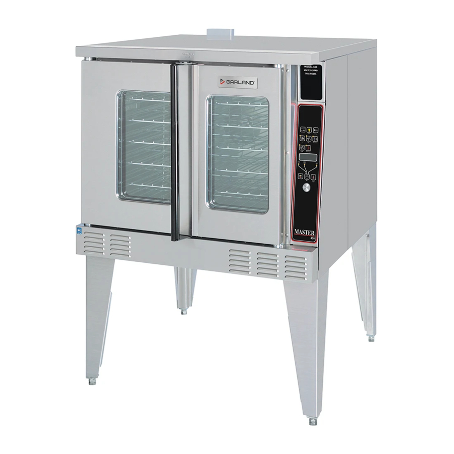
Full size "gas" convection ovens with 200, 410, 450, 455, 470, 475 series controllers
Hide thumbs
Also See for 200:
- Installation and operation manual (48 pages) ,
- Installation and operation manual (24 pages)
Table of Contents
Advertisement
Service Manual For MCO GS/GD
Full Size "Gas" Convection Ovens
With 200, 410, 450, 455, 470, 475 Series
GARLAND COMMERCIAL INDUSTRIES
185 East South Street
Freeland, Pennsylvania 18224
Phone: (570) 636-1000
Fax: (570) 636-3903
Part # MCOSM06 Rev 1(11/03/08)
Controllers
GARLAND COMMERCIAL RANGES, LTD.
1177 Kamato Road, Mississauga, Ontario L4W 1X4
CANADA
Phone: 905-624-0260
Fax: 905-624-5669
Enodis UK LTD.
Swallowfield Way, Hayes, Middlesex UB3 1DQ ENGLAND
Telephone: 081-561-0433
Fax: 081-848-0041
© 2006 Garland Commercial Industries, Inc.
Advertisement
Table of Contents
Troubleshooting

Related Manuals for Garland 200


Summary of Contents for Garland 200
- Page 1 Service Manual For MCO GS/GD Full Size "Gas" Convection Ovens With 200, 410, 450, 455, 470, 475 Series GARLAND COMMERCIAL INDUSTRIES 185 East South Street Freeland, Pennsylvania 18224 Phone: (570) 636-1000 Fax: (570) 636-3903 Part # MCOSM06 Rev 1(11/03/08) Controllers GARLAND COMMERCIAL RANGES, LTD.
- Page 2 Part # MCOSM06 Rev 1 (11/03/08) Page 2...
-
Page 3: Table Of Contents
200 & 300 Series Controllers Calibration ........ - Page 4 Part # MCOSM06 Rev 1 (11/03/08) Page 4...
-
Page 5: Section One Operation Manual
Section One Operation Manual Part # MCOSM06 Rev 1 (11/03/08) Page 5... -
Page 6: Contents
OPERATION . . . . . . . . . . . . . . . . . . . . . . . . . . . . . . . . . .12 Master 200 Mechanical Control with Timer ... . 12 In Off Mode: . -
Page 7: Dimensions & Specifications
2. (120V units) 115V 3/4 HP, 2-speed motor; 1140 and 1725 rpm 60Hz 3. (240V units) 200-240V, 3/4 HP, 2-speed motor; 1140 and 1725 rpm, 60Hz 4. A 6 ft. line cord is provided for each 120V deck with a (NEMA #5-15P) plug. -
Page 8: Installation
NOTE: When checking pressure be sure that all other equipment on the same gas line is on. A pressure regulator is supplied with GARLAND Convection Ovens. Regulator is preset to deliver gas at pressure shown on the rating plate. The appliance and its individual shut-off valve must be... -
Page 9: Gas Connection
There are only two choices for properly venting an oven: 1) canopy hood style or 2) direct venting. The ideal method of venting a GAS Convection Oven is through the use of a properly designed canopy, which should extend 6" (150 mm), beyond all sides of the appliance and 6'6"... - Page 10 A strong exhaust fan will create a vacuum in the room. For an exhaust system vent to work properly, exhaust and make-up air must be balanced properly. For proper air balance contact your local H.V.A.C. contractor. All gas burners and pilots need sufficient air to operate and large objects should not be placed in rear and bottom of this oven, which would obstruct the airflow through the front.
-
Page 11: Testing & Lighting Instructions
Less than 10 feet (3 meters) 2' (60cm) Min. Termination Less than 10 feet (3 meters) from ridge Testing & Lighting Instructions 1. Turn on main gas valve. Remove the lower front cover and the service panel above the control panel. Drop the control panel and leak test all fittings and connections upstream from the service valve located on the redundant combination gas valve. -
Page 12: Operation
OPERATION Master 200 Mechanical Control with Timer In Off Mode: When the oven is off, there are no lights or indicators. Start Up: Press the Cook/Off/Cool Down rocker switch to the "Cook" position. The green lamp will light indicating the oven is powered in cook mode. -
Page 13: Master 300 Solid State Control
This is a patented safety feature. When the ON/OFF key is pressed to turn the oven off and the oven is above 200°F (93°C), the oven will go into an Auto Cool Down mode. In Auto Cool Down, the oven will run the fan on high until the oven cavity drops below 150°F (66°C). -
Page 14: Master 410,450, 455 Controls
NOTE: The "PROBE ERROR" LED will light if the oven temperature probe is malfunctioning or has become damaged or disconnected. Call for service if this occurs. MASTER 410 ELECTRONIC CONTROL MASTER 450 ELECTRONIC CONTROL WITH COOK-N-HOLD MASTER 455 ELECTRONIC CONTROL WITH COOK-N-HOLD &... -
Page 15: Operating The Controls
Cool Down is not active during a cook. When the ON/OFF switch is pressed to turn the oven off and the oven was above 200°F (93°C), the oven will go into an Auto Cool Down mode. In Auto Cool Down, the oven will run the fan on high until the oven cavity drops below 150°F... -
Page 16: Core Probe Operation
Setting the cook temperature, hold temperature and time are done in the same manner. Pressing the SET key will light the TEMP LED. The operator then sets the temperature by rotating the dial on the controller until the desired temperature is shown on the display. Pressing the SET key a second time will light the HOLD LED and allows the operator to select the desired hold temperature as shown on the display. -
Page 17: Master 470/475 Controls
4. Press SET key - HOLD LED will light. 5. Set hold temperature using the dial (factory preset at 200°F). 6. Press SET key - FAN LED will light. 7. Select fan mode using one of the three (3) fan keys ( HIGH, LOW, PULSE ) - the selected fan LED will light. - Page 18 1. Press and hold PROG key for three (3) seconds - all the product key LEDs light. 2. CODE will be displayed. The controller is asking for the access code. Press 4-2-7-5 and the START/CANCEL key. PROD will be displayed indicating you have gained access to Product Programming.
-
Page 19: Programming Product Keys (Master 470)
7. Use the START/CANCEL key to select yes or no. Press the SET key. 8. If yes was selected, the HOLD LED will light. Enter the hold temperature using the dial. (factory preset at 200°F) Press the SET key. FAN will be displayed and the FAN LED will light. -
Page 20: Cooking With The Shelf Timer (475 And 470)
Cooking with the Shelf Timer (Master 475 and Master 470): The shelf timer option is used to independently time each of the up to six different shelves or racks within the oven. NOTE: To use the shelf timer option, at least one product key must be programmed with a cooking profile (temperature, time, fan speed, flex or straight time). -
Page 21: Performance Recommendations
PERFORMANCE RECOMMENDATIONS 1. Preheat oven thoroughly (approximately. 20 minutes) before use. 2. As a general rule, temperature should be reduced 25° to 50° from that used in a standard/conventional oven. Cooking time may also be shorter, so we suggest closely checking the first batch of each product prepared. -
Page 22: Cooking Guide
COOKING GUIDE The following suggested times and temperatures are provided as a starting guide. Elevation, atmospheric conditions, gas supply, recipe, cooking pans and oven loading may affect your actual results. Product White Sheet Cakes – 5 lb White Sheet Cakes – 6 lb Yellow Layer Cake –... -
Page 23: Cook And Hold
Please refer to the operating instructions to program the 450 and 455 control units for cook and hold feature. The times and temperatures listed below are to be used as a starting guide. Your actual results may vary greatly depending on your elevation, gas supply, atmospheric conditions and other items being cooked at the same time. Temperature: 200°F Weight in Rare 2.75... -
Page 24: Problems / Solutions
PROBLEMS / SOLUTIONS Problem If cakes are dark on the sides and not done in the center If cakes edges are too brown If cakes have light outer color If cake settles slightly in the center If cake ripples If cakes are too coarse If pies have uneven color If cupcakes crack on top If meats are browned and not done in center... -
Page 25: Cleaning & Maintenance
(Caution: edges of blower wheel fins may be sharp). 5. Reinstall the air baffle, rack guides and oven racks. This simple practice, if performed on a regular basis will keep your Garland oven operating at peak performance. Page 25... -
Page 26: Motor Care
MOTOR CARE The motor on your convection oven is maintenance free since it is constructed with self-lubricating sealed ball bearings. It is designed to provide durable service when treated with ordinary care. We have a few suggestions to follow on the care of your motor. -
Page 27: Section Two Electronic Pilot & Main Burner
Section Two Electronic Pilot & Main Burner Part # MCOSM06 Rev 1 (11/03/08) Page 27... -
Page 28: Ignition Sequence
IGNITION SEQUENCE First Stage – Trial For Pilot Ignition On every call for heat (system start), the S86 performs an internal safe-start check and shows that a flame-simulating condition is present. During a normal start, the S86 opens the pilot valve in the gas control. This allows gas to flow to the pilot burner. -
Page 29: Trouble Shooting Table
TROUBLE SHOOTING TABLE START TURN GAS SUPPLY OFF. TURN CONTROLLER TO CALL FOR HEAT POWER TO MODULE (24V NOMINAL) SPARK ACROSS IGNITER/ SENSOR GAP TURN GAS SUPPLY ON PILOT BURNER LIGHTS? SPARK STOPS WHEN PILOT IS LIT? MAIN BURNER LIGHTS? SYSTEM RUNS UNTIL CALL FOR HEAT LOSS? CALL FOR HEAT ENDS... -
Page 30: Service
SERVICE Preliminary Check The following visual checks should be made before trouble shooting and after installation or maintenance. 1. Check power to the appliance and S86. 2. Manual shutoff cocks in the gas line must be open. 3. Make certain all wiring connections are clean and tight. 4. -
Page 31: Control Module Flame Sensor Circuit
Examples Of Unsatisfactory Pilot Flames. APPEARANCE SMALL BLUE FLAME LAZY YELLOW FLAME WAVING BLUE FLAME NOISY LIFTING BLOWING FLAME HARD SHARP FLAME Control Module Flame Sensor Circuit. The control module provides AC power to theigniter/sensor that the pilot burner flame rectifies to a direct current. If the flame signal back the control module is not at least 1.0 μA DC, the system will lockout. -
Page 32: G77X Intermittent Pilot Controls
G77x INTERMITTENT PILOT CONTROLS Application Requirements The following are the application requirements of the G77x control. • The G77x can be used on gas-fired equipment with a maximum firing rate of 117kW (400,000 BTU/Hr). Any application over 117kW (40,000 BTU/Hr) must have written approval in advance from the Johnson Controls Heating Products Engineering Department. - Page 33 Figure 2 Thermostat call forheat Prepurge Trial for ignition sensed? Maximum number of trials Interpurge attempted? Ignition lockout (optional LED ashes) Recycle delay period Part # MCOSM06 Rev 1 (11/03/08) Start Flame present when not expected Flame present for 30 seconds? Pilot Energize main valve...
- Page 34 If the pilot burner flame extinguishes during the run state (flameout), the control de-energizes the pilot and main gas valve for the interpurge period. After this period, another trial for ignition is initiated. If the flameout cycle repeats for a total of 16 times (pilot burner flame established then lost), the control will: Wiring Diagram For Integral Spark/Sense Without Vent Damper...
-
Page 35: G76X Direct Spark Ignition Controls
G76X DIRECT SPARK IGNITION CONTROLS Application Requirements Following are the application requirements of the G76xcontrol. • The G76x can be used on gas-fired equipment with a maximum firing rate of 117 kW (400,000 Btu/hr). Any application greater than117 kW (400,000 Btu/hr) must have written approval in advance from the Johnson Controls Heating Products Engineering Department. - Page 36 Fig 3 Sequence of Operation Start Thermostat call for heat Prepurge Trial for ignition Main valve ame sensed? Maximum number of trials Interpurge attempted? Ignition lookout (optinal LED ashes) Page 36 Flame present when not expected Flame present for 30 seconds? Control with ignition recycle?
- Page 37 If the main burner flame extinguishes during the run state, the control de-energizes the main gas valve for an interpurge of 30 seconds. After this period, another trial for ignition is initiated. If this flameout cycle repeats for a total of 16 times (main burner flame established, then lost), the control will: Wiring Diagram for G76x Ignniton Control Main Burner...
- Page 38 Part # MCOSM06 Rev 1 (11/03/08) Page 38...
-
Page 39: Section Three Temperature Calibration
Section Three Temperature Calibration Part # MCOSM06 Rev 1 (11/03/08) Page 39... -
Page 40: General Calibration
GENERAL CALIBRATION Instrumentation A thermocouple type test instrument is preferred for measuring oven temperatures accurately. Mercury thermometers are acceptable providing they can be proven accurate. Regardless of the type instrument used, it is most desirable to double-check it just before making an oven temperature check. -
Page 41: 200 & 300 Series Controllers Calibration
1949 1969 200 & 300 SERIES CONTROLLERS CALIBRATION Both the 200 & 300 series controllers use a 0 to 10.25k OHM potentiometer. First check the sweep on the potentiometer between the middle wire and one of the outside wires for a gradual increase or decrease in the resistance as the potentiometer stem is turned. - Page 42 9. Repeat as required (once is usually enough). 10. Fully tighten both set screws. Page 42 Electric Units – 200 series 1. Remove the temperature dial from the potentiometer. 2. Turn the potentiometer to its highest setting (fully clock wise).
-
Page 43: Section Four Convection Oven Components
Section Four Convection Oven Components Part # MCOSM06 Rev 1 (11/03/08) Page 43... -
Page 44: Doors
4. Push the door toward the hinge and lift up. NOTE: The bottom bearing retainer will stay in place. 5. Remove the right door in the same manner. To Reinstall Doors onto Convection Oven 1. Reverse procedure above. 2. Close doors. -
Page 45: Disassembly Of The Left Door
Disassembly Of The Left Door 1. Once the door has been removed from the oven (refer to previous instructions), remove the 12 truss head 10 x 1/2 Phillips screws. 2. Remove 2 allen head cop screws from the door handle. 3. - Page 46 Disassembly of the Right Door (w/o window) 1. Once the door has been removed from the oven (See previous section), remove 9 truss head s.m.s. 10 x 1/2 from the top, bottom and left side (as shown) from the door panel.
-
Page 47: Door Latch Mechanism
DOOR LATCH MECHANISM To Replace Or Adjust The Door Latch Mechanism 1. Open the oven doors. 2. Remove 2 pan head Phillips screws. Part # MCOSM06 Rev 1 (11/03/08) 3. Lift door latch mechanism up and out of the door assembly. -
Page 48: Motor
MOTOR To Replace Convection Oven Motor Assembly 1. Open doors and remove all oven racks. 2. Remove 4 #10 sheet metal screws (that secure the air baffle) and remove air baffle. 3. Remove six hex nut 1/4-20x7/16" (2A) and lock washers (4A) from the motor mounting studs. -
Page 49: Convection Oven Motor Assembly
Convection Oven Motor Assembly 1. Assemble the motor mount plate, insulation, and motor mount plate inner together by fastening four flat head m.s. 1/4-20x21/2" into the four holes noted on the above drawing. 2. Secure each flat head m/s/ 1/4-20x21/2" with a flat washer and three hex nuts 1/4-20. -
Page 50: Door Microswitch
DOOR MICROSWITCH Page 50 Upper micro switch "Heat" • BROWN wire goes from normally open door switch to terminal T3 on the relay board. • BLUE wire goes from the common on the door switch to terminal T4 on the relay board. Lower micro switch "Cool" • BLACK wire goes from normally open door switch to terminal T6 on the relay board. • WHITE wire goes from common on the door switch to terminal T5 on the relay board. Part # MCOSM06 Rev 1 (11/03/08) -
Page 51: Probes
NOTE: If the cavity core probe is used, the core probe Led will be lit on the control panel, the temperature of the product will be displayed if the product is about 32°F. The programmed range for the core probe is 100°F to 200°F. 60° 70°... -
Page 52: Key Pad Test
KEY PAD TEST Ribbon Connector PIN DETAIL VIEWED FRON FRONT DISPLAY Page 52 PIN NUMBERS On Ribbon Connector 7 6 5 4 3 2 1 KEYPAD & TEST POINTS VIEWED FRON FRONT PIN- OUT TEST POINTS Key # PIN-OUTS 1 & 4 1 &... -
Page 53: Mco Convection Oven Gas Valve
MCO CONVECTION OVEN GAS VALVE SIDE VIEW PILOT VALVE Manual 'A' Valve Inlet Inlet Pressure Regulator Specifications Regulator Adjustment Range Maximum Operating Pressure Minimum Incoming Pressure Part # MCOSM06 Rev 1 (11/03/08) MAIN VALVE Outlet Pilot Outlet Outlet Pressure 3 to 6" WC natural gas 5 to 12"... -
Page 54: Relay Boards
RELAY BOARDS Part # MCOSM06 Rev 1 (11/03/08) Page 54... - Page 55 Testing Through the back side of the Molex Connection with both the controller and the Relay board connected: Power to Controller Door Switch SW1 for HEAT (Upper Switch) Door Switch SW2 for COOL (Lower Switch) (Criteria: You must activate the switch you are testing) Fan High Fan Low Heat Demand...
- Page 56 Motor Relay Board Page 56 Part # MCOSM06 Rev 1 (11/03/08)
-
Page 57: Controls
CONTROLS Display Codes – Prompts Oven is in the OFF mode. Oven cavity temperature is below set point. Oven cavity temperature is above set point. LOAd Oven cavity has reached set temperature - prompt for operator to load oven. SETb Oven has defaulted to factory set back temperature. - Page 58 Part # MCOSM06 Rev 1 (11/03/08) Page 58...
-
Page 59: Section Five Trouble Shooting
Section Five Trouble Shooting Part # MCOSM06 Rev 1 (11/03/08) Page 59... -
Page 60: Controller Operational Tests
CONTROLLER OPERATIONAL TESTS For the Garland (US Range) 200(20) – 300(30) – 410(41) – 450(45) – 455(45+) – 470 – 4712 – 475 FAST convection oven controls. 200 Series Controller (Thermostat only) Turn the oven on, the oven should heat to set temperature within 30 minutes. -
Page 61: Controller Fault Finding
Unless otherwise stated the faults and trouble shooting are the same for all controllers. DISPLAY FAULT Does not apply to 200 and 300 series. Display does not light up Check the incoming voltage to the oven Check for 24 volts AC voltage on pins 1 and 3 of the 15-pin... - Page 62 If the connector is attached the keypad is defective. No Sound Fault Does not apply to 200 and 300 series If the oven operates normally but the sound is different, adjust the piezo so that it is not touching any other component.
-
Page 63: Additional Notes
ADDITIONAL NOTES • Note the pins and voltages for the 15 pin connector from control to relay board Pins 1 & 3 is the power (24 volts-AC ± 10%) Pins 4 & 5 is the heat demand (24 volt DC coil) Pins 6 & 5 is the oven light (24 volt DC coil) Pins 8 & 5 is the low fan (24 volt DC coil) Pins 7 &... -
Page 64: General Trouble Shooting Guide
GENERAL TROUBLE SHOOTING GUIDE Problem Possible Cause Fan will not run A. No Power to Unit No power to motor from relay board C. Micro Switch Not closing Button on key pad not A. Loose ribbon connection between responding key pad and smart board Faulty key pad 'Prob' in display A. - Page 65 Timer slow counting A. Timer is in hours/min down Temperature out of A. 400 series controllers calibration 200 & 300 series controllers C. Potentiometer defective Part # MCOSM06 Rev 1 (11/03/08) Corrective Action Check connections at door switch and relay board Replace upper door switch Check for a minimum 6"...
- Page 66 Part # MCOSM06 Rev 1 (11/03/08) Page 66...
-
Page 67: Section Six Service Bulletins
Section Six Service Bulletins Part # MCOSM06 Rev 1 (11/03/08) Page 67... - Page 68 410, 450, 455 Controllers B-50-2001 Full Size Convection Oven Door Bushings B-59-2001 US Range Control Panel Service Kits B-60-2001 Garland 1/2 Size Control Panel Service Kits B-61-2001 Garland Control Panel Service Kits B-107-2001 Convection Oven Keypad Test Points B-110-2001 Full Size Convection Oven Motor Assy Kits...
- Page 69 Part # MCOSM06 Rev 1 (11/03/08) Page 69...
- Page 70 Part # MCOSM06 Rev 1 (11/03/08) Page 70...
- Page 71 Part # MCOSM06 Rev 1 (11/03/08) Page 71...
- Page 72 Part # MCOSM06 Rev 1 (11/03/08) Page 72...
- Page 73 Part # MCOSM06 Rev 1 (11/03/08) Page 73...
- Page 74 Part # MCOSM06 Rev 1 (11/03/08) Page 74...
- Page 75 Part # MCOSM06 Rev 1 (11/03/08) Page 75...
- Page 76 Part # MCOSM06 Rev 1 (11/03/08) Page 76...
- Page 77 Part # MCOSM06 Rev 1 (11/03/08) Page 77...
- Page 78 Part # MCOSM06 Rev 1 (11/03/08) Page 78...
- Page 79 Part # MCOSM06 Rev 1 (11/03/08) Page 79...
- Page 80 Part # MCOSM06 Rev 1 (11/03/08) Page 80...
- Page 81 Part # MCOSM06 Rev 1 (11/03/08) Page 81...
- Page 82 Part # MCOSM06 Rev 1 (11/03/08) Page 82...
- Page 83 Part # MCOSM06 Rev 1 (11/03/08) Page 83...
- Page 84 Part # MCOSM06 Rev 1 (11/03/08) Page 84...
- Page 85 Part # MCOSM06 Rev 1 (11/03/08) Page 85...
- Page 86 Part # MCOSM06 Rev 1 (11/03/08) Page 86...
- Page 87 Date: February 14, 2002 All Authorized Service Agencies SUBJECT: Convection Oven Controller Troubleshooting MODELS AFFECTED: All Garland & US Range convection ovens Garland / US Range has been receiving a high level of warranty claims for failed controllers, Part Numbers 1905701 1905702...
-
Page 88: Trouble Shooting Guide
DOOR shown in display Unit will not turn ON A. Loose ribbon when button pushed, display reads OFF 1-800-427-6668 www.garland-group.com Page 88 Trouble Shooting Guide POSSIBLE CAUSE A. Turn power on B. Check for voltage from relay board relay board to motor C. - Page 89 Temperature out of A. 400 series controllers calibration B. 200 & 300 series C. Potentiometer defective RESISTANCE vs. TEMPERATURE CHART FOR INTERNAL OVEN The chart below will provide the Ohms at various temperatures. This will enable you to determine if the temperature probe is operable.
- Page 90 200 & 300 Series Controllers ONLY Both the 200 & 300 series controllers use a 0 to 10.25K OHM potentiometer. First check the sweep on the potentiometer between the middle wire and one of the outside wires for a gradual increase or decrease in the resistance as the potentiometer stem is turned.
- Page 91 8. Tighten set screw down 9. Repeat as required (once is usually enough) 10. Fully tighten both set screws ELECTRIC Units – 200 Series 1. Remove the temperature dial from the potentiometer 2. Turn potentiometer to its highest setting ( fully clock wise ) 3.
- Page 92 All Authorized Service Agencies SUBJECT: 410, 450, 455 CONTROLLERS (USED ON GARLAND AND U.S. RANGE CONVECTION OVENS) CUSTOMER COMPLAINT: Timer will not count down. We have had a number of calls on this and a lot of controllers have been replaced thinking that there is a problem with the controller.
- Page 93 The attached test points are a useful service tool to better determine if the problem is with the keypad, controller, relay board assembly or other. The attached pages shows the PIN-OUT test points for the keypad used on the above Garland & US Range convection ovens.
- Page 94 Ribbon Connector DISPLAY Page 94 PIN DETAIL PIN NUMBERS VIEWED FROM FRONT On Ribbon Connector 7 6 5 4 3 2 1 KEYPAD & TEST POINTS VIEWED FROM FRONT Page 8 of 9 Part # MCOSM06 Rev 1 (11/03/08)
- Page 95 2 & 4 2 & 5 2 & 6 2 & 7 3 & 4 3 & 5 3 & 6 3 & 7 www.garland-group.com Page 9 of 9 OVERLAY MARKINGS SET BACK COOL DOWN PROGRAM ACTUAL TEMP CAVITY LIGHT...
- Page 96 Model Affected: Half-Size Garland Gas convection oven models, MCO-G-5LE and MCO-G- 5RE with 300/400 series electronic control panels. There are now new field service manual control panel kits available for the Garland gas half-size convection ovens. These two kits include the complete control panel assembly and will convert an existing 300/400 series electronic control panel to the 200 series manual control panel.
- Page 97 Garland ICO ELECTRIC convection ovens. Reference Garland bulletin B-66-2002. The Garland ICO ELECTRIC convection oven requires the use of pn 1032400 thermostat. This thermostat is rated for 30 AMPS. The GAS thermostat, pn G02902-01 is rated at 1 AMP. If it is installed in an ELECTRIC convection oven it will not operate accurately / fail prematurely.
- Page 98 All Authorized Service Agencies Subject: Rating Plate Motor Return Model Affected: Garland Convection or Moisture Plus Oven Effective immediately, when replacing a failed motor for a convection oven or Moisture Plus oven, it will be necessary for you to return the rating plate label from the motor along with your warranty claim report and packing slip.
- Page 99 The following part numbers are affected by this bulletin on Garland convection and Moisture Plus ovens: Part # 1686711 1686712 1686703 1773802 1951501 1951502 CK1003090 CK1003091 Ck1003094 CK1003095 CK1003099 CK00-011 4518320 4518319 1615001 Please contact The Garland/US Range Technical Service Department with any question.
- Page 100 Part # MCOSM06 Rev 1 (11/03/08) Page 100...
-
Page 101: Section Seven Wiring Diagrams
Section Seven Wiring Diagrams Part # MCOSM06 Rev 1 (11/03/08) Page 101... - Page 102 Master Convection Ovens Wiring Diagrams GAS MODELS HoneyWell Ignition Modules 200 Controller Voltage (Honeywell Ignition Module) 120V 1949511-R02 GAS MODELS Johnson Ignition Modules 200 Controller Voltage (Johnson Ignition 120V 1949511-R03 ELECTRIC MODELS Mechanical Mechanical Voltage Control Control 1 speed 2 speed...
- Page 103 Part # MCOSM06 Rev 1 (11/03/08) Page 103...
- Page 104 Part # MCOSM06 Rev 1 (11/03/08) Page 104...
- Page 105 Part # MCOSM06 Rev 1 (11/03/08) Page 105...
- Page 106 Part # MCOSM06 Rev 1 (11/03/08) Page 106...
- Page 107 Part # MCOSM06 Rev 1 (11/03/08) Page 107...
- Page 108 Part # MCOSM06 Rev 1 (11/03/08) Page 108...
- Page 109 Part # MCOSM06 Rev 1 (11/03/08) Page 109...
- Page 110 Part # MCOSM06 Rev 1 (11/03/08) Page 110...
- Page 111 Part # MCOSM06 Rev 1 (11/03/08) Page 111...
- Page 112 Part # MCOSM06 Rev 1 (11/03/08) Page 112...
- Page 113 Part # MCOSM06 Rev 1 (11/03/08) Page 113...
- Page 114 Part # MCOSM06 Rev 1 (11/03/08) Page 114...
- Page 115 Part # MCOSM06 Rev 1 (11/03/08) Page 115...
- Page 116 Part # MCOSM06 Rev 1 (11/03/08) Page 116...
- Page 117 Part # MCOSM06 Rev 1 (11/03/08) Page 117...
- Page 118 Part # MCOSM06 Rev 1 (11/03/08) Page 118...
- Page 119 Part # MCOSM06 Rev 1 (11/03/08) Page 119...
- Page 120 Part # MCOSM06 Rev 1 (11/03/08) Page 120...
- Page 121 Part # MCOSM06 Rev 1 (11/03/08) Page 121...
- Page 122 Part # MCOSM06 Rev 1 (11/03/08) Page 122...
- Page 123 Part # MCOSM06 Rev 1 (11/03/08) Page 123...