Advertisement
Quick Links
Download this manual
See also:
Manual
3
C H A P T E R
Channelized T3 Trunk Card
The Cisco AS5800 universal access server supports a channelized T3 (CT3) ingress interface that
provides asynchronous aggregation of channelized interfaces and multiplexing on a single T3 facility.
The CT3 trunk card is installed in the Cisco 5814 dial shelf chassis in slots 0 to slot 5. The
Cisco AS5800 currently supports as many as two CT3 trunk cards.
This chapter explains how to remove and replace a CT3 trunk card in the Cisco 5814 dial shelf chassis,
and also includes steps for verifying and troubleshooting your trunk card installation and configuring
your software.
CT3 Trunk Card Overview
The CT3 trunk card contains an onboard M13 multiplexer, which multiplexes 28 separate T1 lines into
a single T3 line. Each CT3 trunk card installed in the Cisco 5814 dial shelf contains all necessary
functionality to terminate link signaling and incoming digital calls.
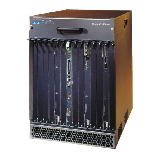
Figure 3-1 shows the CT3 trunk card.
Cisco AS5800 Universal Access Server Dial Shelf Card Guide
3-1
78-7097-03
Advertisement

Related Manuals for Cisco AS5800


Summary of Contents for Cisco AS5800
- Page 1 T3 facility. The CT3 trunk card is installed in the Cisco 5814 dial shelf chassis in slots 0 to slot 5. The Cisco AS5800 currently supports as many as two CT3 trunk cards.
- Page 2 Responds to time-sensitive signaling. Each CT3 trunk card can supply two clocks from any two of its 28 ports. You can assign priorities to these clocks or accept the default values assigned by the software. Cisco AS5800 Universal Access Server Dial Shelf Card Guide 78-7097-03...
- Page 3 Supports online insertion and removal (OIR), a feature that allows you to remove and replace a trunk • card in the Cisco 5814 dial shelf while the system is operating without disrupting other cards and their associated calls. If you remove a trunk card while the system is operating, all calls associated with the CT3 lines on that card are dropped.
- Page 4 Channelized T3 Trunk Card CT3 Trunk Card Overview Clocking All Cisco AS5800 access server trunk cards use the same transmit clock. This clock can originate from the following sources: • TDM clock source—A priority value from 1 to 50 that is applied to a clock source when multiple clock sources are used •...
- Page 5 LALM Yellow Local alarm—Lights to indicate a T1 alarm condition was encountered by software for a particular port; remains OFF when the operating condition is normal. Cisco AS5800 Universal Access Server Dial Shelf Card Guide 78-7097-03...
- Page 6 The CT3 front panel is designed with two types of cable connectors (see Figure 3-4). The BNC connectors are used to connect the cables carrying the T3 signals. The bantam jacks are used for local BERT circuit testing to the DS1 level. Cisco AS5800 Universal Access Server Dial Shelf Card Guide 78-7097-03...
- Page 7 The CT3 trunk card front panel is designed with an alphanumeric display to provide trunk card status and port monitoring information (see Figure 3-3). Test-port functionality is supported by Cisco IOS Release 12.0(6)T and later releases. Cisco AS5800 Universal Access Server Dial Shelf Card Guide...
- Page 8 CT3 board. To disable drop-and-insert mode, enter the test trunk drop-insert off privileged EXEC command as follows: shelf/slot/unit AS5800# test trunk drop-insert off Cisco AS5800 Universal Access Server Dial Shelf Card Guide 78-7097-03...
-
Page 9: Monitor Mode
T1 line at the test port. To select another port number, press the push button again and hold it for two or Note more seconds. You can now toggle to another port number. Cisco AS5800 Universal Access Server Dial Shelf Card Guide 78-7097-03... -
Page 10: Specifications
To connect the T3 lines, follow these steps: Attach the end of the T3 cable directly to the BNC receptacle on the trunk card (see Figure 3-6). Step 1 Cisco AS5800 Universal Access Server Dial Shelf Card Guide 3-10 78-7097-03... -
Page 11: Verifying And Troubleshooting The Installation
Verifying and Troubleshooting the Installation When you first power ON your Cisco AS5800, all LEDs light while the system runs a series of diagnostics. After the system passes initial diagnostics, all LEDs shut off. The LEDs then light again as described in Table 3-1. -
Page 12: Configuration Commands
Access Server Hardware Installation Guide. Configuring the CT3 Trunk Card The Cisco 5814 dial shelf recognizes trunk cards only in dial shelf slots 0 to 5. Therefore, install trunk cards only in the first six slots. If you are replacing a dial shelf card by installing a new dial shelf card of the same type in the same slot, the system software recognizes the new dial shelf card interfaces and brings them up automatically. - Page 13 T3 line with a value from 1 to 28. Step 12 AS5800(config-controller)# clock source Configure the clock source as an internal clock line (internal) or a recovered clock (line). Cisco AS5800 Universal Access Server Dial Shelf Card Guide 3-13 78-7097-03...
- Page 14 G G G G G G G G G G G G G G G G G G G G G G G G G G G G B B B B B B B B B B B B B B B B B B B B G G G G G G G G Cisco AS5800 Universal Access Server Dial Shelf Card Guide 3-14...
- Page 15 49208 C-bit Coding Violation, 0 P-bit Err Secs, 0 P-bit Severely Err Secs, 0 Severely Err Framing Secs, 2 Unavailable Secs, 0 Line Errored Secs, 10 C-bit Errored Secs, 10 C-bit Severely Errored Secs Cisco AS5800 Universal Access Server Dial Shelf Card Guide 3-15 78-7097-03...
- Page 16 A typical T1 controller configuration appears as follows: T1 controller configuration: ---------------------------- controller T1 1/0/0:1 framing esf pri-group timeslots 1-24 controller T1 1/0/0:2 channel-group 0 timeslots 1-24 controller T1 1/1/0:28 cas-group 0 timeslots 1-24 Cisco AS5800 Universal Access Server Dial Shelf Card Guide 3-16 78-7097-03...