Table of Contents
Advertisement
Quick Links
Advertisement
Table of Contents

Related Manuals for Furuno FCV-1100L


Summary of Contents for Furuno FCV-1100L
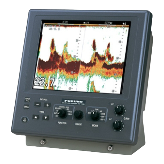
- Page 1 Back COLOR LCD SOUNDER FCV-1100L...
- Page 2 Your Local Agent/Dealer Your Local Agent/Dealer 9-52 Ashihara-cho, 9-52 Ashihara-cho, Nishinomiya, Japan Nishinomiya, Japan Telephone : Telephone : 0798-65-2111 0798-65-2111 0798-65-4200 0798-65-4200 FIRST EDITION : FIRST EDITION : AUG. AUG. 2001 2001 Printed in Japan Printed in Japan All rights reserved. All rights reserved.
- Page 3 The installer of the equipment is solely responsible for the proper installation of the equipment. FURUNO will assume no responsibility for any damage associated with improper installation. Be sure that the power supply is compatible with the voltage rating of the equipment.
- Page 4 CAUTION CAUTION The transducer cable must he handled Ground the equipment to carefully, following the guidelines prevent mutual interference. below. Keep fuels and oils away from the Observe the following compass safe cable. distances to prevent interference to a Locate the cable where it will not be magnetic compass: damaged.
-
Page 5: Table Of Contents
TABLE OF CONTENTS SYSTEM CONFIGURATION................iv EQUIPMENT LISTS ....................v 1. MOUNTING ....................1-1 1.1 Display Unit ....................... 1-1 1.2 Transducer......................... 1-4 1.3 Water Temperature Sensor (option) ................1-4 2. WIRING......................2-1 2.1 Wiring Standard Equipment ..................2-2 2.2 Wiring Optional Equipment ..................2-3 2.3 Input/Output Sentences ..................... -
Page 6: System Configuration
SYSTEM CONFIGURATION... -
Page 7: Equipment Lists
EQUIPMENT LISTS EQUIPMENT LISTS Standard supply Name Type Code No. Remarks Display unit CV-1100L Spare Parts SP02-04401 001-402-100 1 set Fuse Accessories FP02-05300 000-012-509 1 set Hood CP02-06900 000-012-508 MJ-A3SPF0013-035 (3.5 m), Installation Materials 1 set CP02-06901 Options Name Type Code No. - Page 8 EQUIPMENT LISTS Available transducers 1 kW transducer Frequency Hull Thru-Hull Transducer Tank (kHz) Material Pipe Steel 28F-8 50B-6/6B Steel TWB-6000 (2) T-656 28F-8 28/50 50B-9/9B Steel 28F-8 50F-8G Steel 28F-8 28/68 68F-8H Steel TWB-6000 (2) T-657 28F-8 28/88 88B-8 Steel 28F-8 28/200 200B-5S...
- Page 9 EQUIPMENT LISTS 2 kW transducer Frequency Hull Thru-Hull Transducer Tank (kHz) Material Pipe Steel TFB-7000 (2) T-634 28F-18 28/50 50B-12 Steel 28F-18 28/68 68F-30H TRB-1100 (2) T-634-F Steel TFB-7000 (2) T-636 28F- 18 28/88 88B-10 TFB-1100 (2) T-636-F Steel TFB-7000 (2) T-638 28F-18 28/200...
- Page 10 EQUIPMENT LISTS 3 kW transducer Frequency Hull Thru-Hull Transducer Tank (kHz) Material Pipe Steel TFB-7000 (2) T-681 28/50 28F-24H, 50F-24H TRB-1100 (2) T-681-F Steel 28/68 28F-24H, 68F-30H Steel TFB-7000 (2) T-682 28/88 28F-24H, 88F-126H TRB-1100 (2) T-682-F Steel 28/107 28F-24H, 100B-10R Steel 28/150 50B-6/6B, 88B-8...
- Page 11 EQUIPMENT LISTS 1 kW/2 kW transducer Frequency Hull Thru-Hull Output Transducer Tank (kHz) Material Pipe Steel 28F-8 28/50 50B-12 Steel 28F-8 28/68 68F-30H Steel 28F-8 28/88 88B-10 Steel TWB-6000 (2) T-657 28F-8 28/200 200B-8/8B/8N Steel 50B-6/6B 88B-10 Steel 50B-9/9B 50/88 88B-10 1 k/2 k Steel...
- Page 12 EQUIPMENT LISTS 1 kW/3 kW transducer Output Frequency Hull Thru-Hull Transducer Tank (kHz) Material Pipe Steel 28F-8 28/45 45F-12H Steel 28F-8 28/50 50F-24H Steel 28F-8 28/68 68F-30H Steel 28F-24H, 28/88 100B-10R Steel 28F-8 28/150 88F-126H Steel 28F-8 28/107 100B-10R Steel 28F-8 28/150 150B-12H...
- Page 13 EQUIPMENT LISTS Output Frequency Hull Transducer Thru-Hull Pipe Tank (kHz) Material Steel 50B-6/6B 200B-12H Steel 50B-9/9B 50/200 200B-12H Steel 50F-8G 200B-12H Steel 68F-8H 68/107 100B-10R 1 k/3 k Steel 68F-8H 68/150 150B-12H Steel 68F-8H 68/200 200B-12H Steel 88B-8 88/150 150B-12H Steel 88B-8 88/200...
- Page 14 EQUIPMENT LISTS 2 kW/3 kW transducer Output Frequency Hull Transducer Thru-Hull Pipe Tank (kHz) Material Steel 28F-18 28/45 45F-12H Steel 28F-18 28/50 50F-24H Steel 28F-18 28/68 68F-30H Steel 28F-18 28/88 88F-126H Steel 28F-18 TFB-7000 (2) T-636 28/107 100B-10R TRB-1100 (2) T-636-F Steel 28F-18...
- Page 15 EQUIPMENT LISTS 3 kW/2 kW transducer Output Frequency Hull Transducer Thru-Hull Pipe Tank (kHz) Material Steel 28F-24H 28/50 50B-12 Steel 28F-24H 28/68 68F-30H Steel 28F-24H 28/88 88B-10 Steel 28F-24H 28/200 200B-8/8B/8N Steel 50F-24H 50/88 88B-10 3 k/2 k Steel 50F-24H 50/200 200B-8/8B/8N Steel...
- Page 16 EQUIPMENT LISTS This page is intentionally left blank.
-
Page 17: Mounting
1. MOUNTING 1.1 Display Unit WARNING Turn off the power at the switchboard before beginning the installation. Fire or electrical shock can result if the power is left on. Mounting considerations Locate the unit out of direct sunlight. The operator should face the bow while viewing the display screen. Select a location where the display screen can be easily observed while operating the control unit. - Page 18 1. MOUNTING Mounting procedure Desktop mounting 1. Loosen two M6 x 25 bolts at the front of the display unit to remove the mounting base. M6 x 25 bolts Removing the display unit from the mounting base 2. Use the four tapping screws (5 x 20, supplied as installation materials) to fasten the mounting base.
- Page 19 1. MOUNTING Flush mounting 1. Make cutout in mounting location referring to the outline drawing show below. 2. Fasten the display unit to the mounting location with four pan head screws. Flush mounting display unit...
-
Page 20: Transducer
1. MOUNTING 1.2 Transducer The performance of the video sounder depends upon the transducer position. A place least affected by air bubbles should be selected since turbulence blocks the sounding path. Further, select a place least influenced by engine noise. It is known that air bubbles are fewest at the place where the bow first falls and the next wave rises, at usual cruising speed. - Page 21 1. MOUNTING Thru-hull mount water temperature sensor T-02MSB, T-03MSB Select a suitable mounting location considering the following points: Select a mid-boat flat position. The sensor does not have to be installed perfectly perpendicular; however, the location should not be such that the transducer may be damaged when the boat is dry-docked.
- Page 22 1. MOUNTING Through-hull mount water temperature/speed sensor ST-02MSB, ST02-PSB Select a suitable mounting location considering the following: Select a mid-boat flat position. The sensor does not have to be installed perfectly perpendicular. The sensor must not be damaged in dry-docking operation. Select a place apart from equipment generating heat.
-
Page 23: Wiring
2. WIRING Refer to the interconnection diagram at the back of this manual for detailed information. Wiring diagram for standard-type FCV-1100L... -
Page 24: Wiring Standard Equipment
2. WIRING Wiring Standard Equipment Transducer Separate the transducer cable well away from power cables to prevent interference. Connect the cable to the transducer connector at the rear of the display unit. Fabricate the cable as below. Sheild Shield form Cable Cable clamp Connector... -
Page 25: Wiring Optional Equipment
2. WIRING Wiring Optional Equipment Navigator Use cable type MJ-A6SPF0011/0012 (option) to connect the navigator to the NMEA connector. Water temperature sensor T-02MSB, T-02MTB, T-03MSB Connect the water temperature sensor cable to the TEMP connector. Input/Output Sentences Input sentences Sentence Data Remarks Range/bearing to waypoint... - Page 26 2. WIRING This page is intentionally left blank.
-
Page 27: Initial Setting
This section provides the information necessary for initial setup of the equipment. First turn on the power and set display language. In addition, either transducer used, by model number (FURUNO transducer only) or by specifications. Language Setting 1. Turn on the power. The following display appears. -
Page 28: Transducer Data
36 kHz 32/40 (3 kW) 41 kHz 40/75 (3 kW) 50/200/400 (2 kW) Honda 50 kHz 50/3K/3F (3 kW) 67 kHz 40/75 (3 kW) 200 kHz 50/200/400 (2 kW) Suzuki 50, 200 kHz TGM50/200 Same as Furuno makes 50/200-1T (1 kW) - Page 29 3. INITIAL SETTINGS Entering transducer data by transducer model number Note 1: If you are continuing from paragraph 3.1 go to step 2. Note 2: If you have already entered transducer settings and to reconfirm them turn on the power while pressing any key. 1.
- Page 30 3. INITIAL SETTINGS 3. Press [!] to select [HIGH] CONNECTION or [LOW] CONNECTION (whichever is installed), and then press [+] or [-] to show the dialog box. Select CONNECTED for the connection of transducer. 4. Press ["] or [!] to close the dialog box. 5.
-
Page 31: Transducer Setting
3. INITIAL SETTINGS Transducer setting Change the terminal board setting at the rear of the display unit according to the transducer connected. Note the alphabet which appeared when selecting the transducer type on the installation main menu (page 3-4), and then do the following procedures. 1. - Page 32 For dealer: When connecting the transducers which are not programmed, contact to PRODUCT SERVICE SECTION SERVICE CENTER, FURUNO HEAD OFFICE. For new transducer or other make of transducer see FURUNO information for further information. Note 1: If you are continuing from paragraph 3.1, go to step 2.
-
Page 33: Water Temperature Sensor Setting
3. INITIAL SETTINGS d) Use [+] or [-] to set the value for the frequency which is connected, and then press [!] or ["] to close the dialog box. (Available range: HIGH; 40 – 220 kHz, LOW; 25 – 220 kHz) e) To operate the transducer in reduced power (for example, when vessel is in dry dock), press ["] to select PWR REDUCTION, and then press [+] or [-] to open the dialog box. - Page 34 3. INITIAL SETTINGS 6. Press ["] to select TEMP INPUT, and then press [+] or [-] to open the dialog box. SENSOR NMEA 7. Use [+] or [-] to select source of water temperature data, and then press [!] or ["] to close the dialog box.
-
Page 35: Nav Data, Heading Sensor Setting
3. INITIAL SETTINGS Nav Data, Heading Sensor Setting Select navigator and heading sensor used as below. 1. Turn on the power and turn the [FUNCTION] switch to the MENU position. 2. Press [!] and [+] to select SYSTEM at the top of the screen. 3. - Page 36 3. INITIAL SETTINGS Actual value - Indication of FCV-1100L Adjustment value = x 100 (%) Actual value Press [!] or ["] to close the dialog box. 10. Press ["] to select SPEED OUTPUT, and then press the [+] or [-] key to open the dialog box.
-
Page 37: Propagation Velocity
3. INITIAL SETTINGS Propagation Velocity This section provides the information for adjustment of propagation velocity. Normally, no adjustment is necessary, however if the depth indication is wrong, lower or raise propagation velocity as appropriate. 1. Turn on the power while pressing any key to show the installation main menu. 2. -
Page 38: Demonstration Mode
3. INITIAL SETTINGS Demonstration Mode The demonstration mode provides a simulated video sounder picture. Connection of the transducer is not necessary. All controls are operational. 1. Turn on the power while pressing any key to display the installation main menu. 2. -
Page 39: Restoring Default Settings
3. INITIAL SETTINGS Restoring Default Settings The procedure below restores most default settings. Are not affected: target setting, language, demo mode, transducer settings, user color settings and user clutter settings. 1. Turn on the power and turn the [FUNCTION] switch to the MENU position. 2. - Page 40 This page is intentionally left blank.
-
Page 41: Appendix 1 Transducer 50Bl-12/50Bl-24H
APPENDIX 1 TRANSDUCER 50BL-12/50BL-24H When using the transducer 50BL-12/50BL-24H, see this appendix. Transducer, thru-hull pipe and tank list Frequency Hull Tank Fasten inside Fasten outside Transducer (kHz) Material (Code No.) hull (Code No.) hull (Code No.) T-693 TWB-6000 TFB-7000 Steel (000-015-044) (000-015-207) (000-015-209) -
Page 42: Appendix 2 New Blt Transducers
APPENDIX 2 NEW BLT TRANSDUCERS A new type BLT transducer (Bolt-clamp Langevin Transducer) has been developed for this echo sounder. The BLT transducer has large bandwidth, good sound efficiency, compact structure and is reinforced for protection against slamming. Transducer, thru-hull pipe and tank list Frequency Hull Tank... - Page 43 APPENDIX 2 NEW BLT TRANSDUCERS 50/88 50BL-24HR/88-126H T-682 TWB-6000 (2) TFB-7000 (2) Steel (000-015-851) (000-015-207) (000-015-209) T-682F TRB-1100 (2) (000-015-852) (000-015-219) 28/200 28BL-12HR/200B-12H T-683 TWB-6000 (2) TFB-7000 (2) Steel (000-015-853) (000-015-207) (000-015-209) T-683F TRB-1100 (2) (000-015-854) (000-015-219) 38/200 38BL-15HR/200B-12H T-683 TWB-6000 (2) TFB-7000 (2) Steel...
- Page 44 APPENDIX 2 NEW BLT TRANSDUCERS This page is intentionally left blank. AP-4...
- Page 49 Nov. 14, '02...