Table of Contents
Advertisement
Advertisement
Table of Contents

Related Manuals for ProForm CROSSWALK 397


Summary of Contents for ProForm CROSSWALK 397
- Page 1 ModelNo.831.24843.4 Serial No. User's Manual Write the serial number in the space above for reference. Serial Number Decal • Assembly • Operation • Maintenance • Part List and Drawing Sears, Roebuck and Co. Hoffman Estates, IL 60179 lira ®_,o_w_ ",,-- www.iFit,com...
- Page 2 TABLE OF CONTENTS WARNING DECAL PLACEMENT ............... IMPORTANT PRECAUTIONS ..............BEFORE YOU BEGIN ................ PART IDENTIFICATION CHART ..............ASSEMBLY ................OPERATION AND ADJUSTMENT ............. HOW TO FOLD AND MOVE THE TREADMILL ........... TROUBLESHOOTING ..............EXERCISE GUIDELINES ..............PART LIST ................EXPLODED DRAWING ..............
- Page 3 iMPORTANT PRECAUTIONS WARNING: To reduce the risk ofburns, f=re, e ectric shock, or njury topersons, read all important precautions and instructions in this manual and all warnings on your treadmill before using your treadmill. Sears assumes no responsibility for personal injury or property damage sus- tained by or through the use of this product.
- Page 4 20. The heart rate monitor is not a medical 24. Do not change the incline of the treadmill device. Various factors, including the user's placing objects under the treadmill. movement, may affect the accuracy of heart rate readings. The heart rate monitor 25.
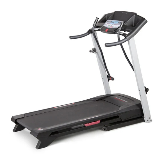
- Page 5 BEFORE YOU BEGIN Thank you for selecting the new PROFORM "_R_ reading this manual, please see the back cover of this CROSSWALK 397 treadmill. The CROSSWALK 397 manual. To help us assist you, note the product model treadmill provides an impressive selection of features number and serial number before contacting us.
- Page 6 PART iDENTiFiCATiON CHART Use the drawings below to identify small parts used for assembly. The number in parentheses below each draw- ing is the key number of the part, from the PART LIST near the end of this manual. The number following the key number is the quantity used for assembly.
- Page 7 ASSEMBLY Assembly requires two persons. • To identify small parts, see page 6. Place all parts in a cleared area and remove the • Assembly requires the following tools: packing materials. Do not dispose of the packing the included hex keys materials until you finish all assembly steps.
- Page 8 Identify the Right Upright (76). Have a second person hold the Right Upright near the Base (74). See the inset drawing. Tie the wire tie in the Right Upright (76) securely around the end of the Upright Wire (63). Then, insert the Upright Wire into the lower end of the Right Upright as you pull the other end of the wire tie through the Wire...
- Page 9 Identify the Left and Right Handrails (59, 64). Remove the four 5/16" x 3/4" Screws (5) and four 5/16" Star Washers (6) from the bottoms and sides of each Handrail. Hold the Right Handrail (64) near the Right Upright (76). Insert the wire tie on the Upright Wire (63) through the hole in the bottom and pull it out of the hole in the side of the Right Handrail as shown.
- Page 10 With the help of a second person, hold the con- Console sole assembly near the Right Handrail (64). Assembl Connect the Upright Wire (63) to the console wire. See the inset drawing. The connectors should slide together easily and snap into place.
- Page 11 Attach the two Console Clamps (45) to the con- Console sole assembly with four #8 x 1" Screws (7). Assembly 10. Identify the Left and Right Upper Body Arms (44, 34). Make sure that the Left Upper Body Arm (44) is positioned as shown.
- Page 12 11. Attach the Latch Housing (67) with the Latch Spacer (82) to the Left Upright (66) with two #10 x 1 1/2" Screws (8); make sure that the knob is on the indicated side. Start both Screws, and then tighten them. Be careful not to over= tighten the Screws.
- Page 13 OPERATION AND ADJUSTMENT HOW TO CONNECT THE POWER CORD nominal 120=volt circuit capable of carrying 15 or more amps. To avoid overloading the circuit, do Use a Surge Suppressor not plug other electrical devices, except for low= power devices such as cell phone chargers, into Your treadmill, like other electronic equipment, can be the surge suppressor or into an outlet on the same...
- Page 14 CONSOLE DIAGRAM c 0sswALK INCLINE FEATURES OFTHE CONSOLE To turn on the power, see page 15. To use the man= ual mode, see page 15. To use a preset workout, The treadmill console offers an impressive array of see page 17. To use the information mode, see features designed to make your workouts more effec- page 18.
- Page 15 HOW TO TURN ON THE POWER HOW TO USE THE MANUAL MODE iMPORTANT: if the treadmill has been exposed to insert the key into the console. cold temperatures, allow it to warm to room tern= See HOW TO TURN ON THE POWER at the left. perature before turning on the power, if you do not do this, you may damage the console displays or Select the manual mode.
- Page 16 Follow your progress with the displays. Measure your heart rate if desired. The far left display-- Before using the When you select the handgrip heart manual mode, the matrix rate monitor, re- move the sheets will display a track that represents 1/4 mile (400 of plastic from the metal contacts...
- Page 17 HOW TO USE A PRESET WORKOUT will begin to flash. If a new speed and/or incline setting is programmed for the next segment, the insert the key into the console. new speed and/or incline setting will appear in the displays. The treadmill will then automatically ad- See HOW TO TURN ON THE POWER on page 15.
- Page 18 THE iNFORMATiON MODE HOW TO USE THE CROSSWALK ARMS The console features an information mode that keeps As you walk on the treadmill, you can hold the hand- track of the total distance that the walking belt has rails or use the crosswalk arms. To exercise your arms, moved and the total number of hours that the treadmill shoulders, and back for a total body workout, move the has been used.
- Page 19 HOW TO FOLD AND MOVE THE TREADMILL HOW TO FOLD THE TREADMILL HOW TO MOVE THE TREADMILL Before folding the treadmill, adjust the incline to Before moving the treadmill, fold it as described at the the lowest position, if you do not do this, you may left.
- Page 20 TROUBLESHOOTING Most treadmill problems can be solved by follow- the demo mode, hold down the Stop button for a ing the simple steps below. Find the symptom that few seconds. If the displays are still lit, see THE applies, and follow the steps listed, if further assis= INFORMATION MODE on page 18 to turn off the demo mode.
- Page 21 SYMPTOM: The walking belt slows when walked on SYMPTOM: The walking belt is off=center or slips when walked on Use only a surge suppressor that meets all of the specifications described on page 13. if the walking belt is off=center, first remove the key and UNPLUG THE POWER CORD.
- Page 22 EXERCISE GUiDELiNES Burning Fat--To burn fat effectively, you must exer- cise at a low intensity level for a sustained period of time. During the first few minutes of exercise, your body uses carbohydrate calories for energy. Only after the first few minutes of exercise does your body begin to use stored fat calories for energy.
- Page 23 SUGGESTED STRETCHES The correct form for several basic stretches is shown at the right. Move slowly as you stretch--never bounce. 1. Toe Touch Stretch Stand with your knees bent slightly and slowly bend forward from your hips. Allow your back and shoulders to relax as you reach down toward your toes as far as possible.
- Page 24 PART LIST Model No. 831.24843.4 Rll12A Key No. Qty. Description Key No. Qty. Description #8 x 1/2" Ground Screw Left Rear Foot 3/8" x 3 1/4" Screw Left Upper Body Arm 3/8" Star Washer Console Clamp #8 x 3/4" Screw Right Rear Foot 5/16"...
- Page 25 1::1 © ©...
- Page 26 EXPLODED DRAWING B Model No. 831.24843.4 Rll12A...
- Page 27 EXPLODED DRAWING C Model No. 831.24843.4 Rll12A 69-<_ 72 _78...
- Page 28 Your Home For repair--in your home--of all major brand appliances, lawn and garden equipment, or heating and cooling systems, no matter made it, no matter sold iiiiiiiiiiiiiiiii For the replacement parts, accessories, and user's manuals that you need to do-it-yourself. iiiiiiiiiiiiiiiii iiiiiiiiiiiiiiiii For Sears professional...