ProForm 395E User Manual
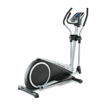
Elliptical exerciser
Hide thumbs
Also See for 395E:
- User manual (28 pages) ,
- Manual (28 pages) ,
- Manual del usuario (28 pages)
Table of Contents
Advertisement
Advertisement
Table of Contents

Related Manuals for ProForm 395E


Summary of Contents for ProForm 395E
- Page 1 Model No. 831.23953.3 Serial No. ELLIPTICAL EXERCISER Write the serial number in the space User's Manual above for reference. Serial Number Decal (under frame) • Assembly • Operation • Maintenance • Part List and Drawing Sears, Roebuck and Co. Noffman Estates, IL 60179...
- Page 2 TABLE OF CONTENTS WARNING DECAL PLACEMENT ............... IMPORTANT PRECAUTIONS ..............BEFORE YOU BEGIN ................ PART IDENTIFICATION CHART ..............ASSEMBLY ................HOW TO USE THE ELLIPTICAL .............. FCC INFORMATION ................ MAINTENANCE AND TROUBLESHOOTING ............ EXERCISE GUIDELINES ..............PART LIST ................EXPLODED DRAWING ..............ORDERING REPLACEMENT PARTS ...........
- Page 3 iMPORTANT PRECAUTIONS WARNING: To reduce the risk ofserious injury, read a , important precautions instructions in this manual and all warnings on your elliptical before using your elliptical. Sears assumes no responsibility for personal injury or property damage sustained by or through the use of this product.
- Page 4 BEFORE YOU BEGIN Thank you for selecting the revolutionary PROFORM _ manual. To help us assist you, note the product model 395 E elliptical. The 395 E elliptical provides an impres- number and serial number before contacting us. The model number and the location of the serial number sive selection of features designed to make your decal are shown on the front cover of this manual.
- Page 5 PART iDENTiFiCATiON CHART Use the drawings below to identify the small parts needed for assembly. The number in parentheses below each drawing is the key number of the part, from the PART LIST near the end of this manual. The number following the key number is the quantity needed for assembly.
- Page 6 ASSEMBLY Assembly requires two persons. • in addition to the included tool(s), assembly requires the following tool(s): Place all parts in a cleared area and remove the one Phillips screwdriver packing materials. Do not dispose of the packing materials until you finish all assembly steps. Assembly may be easier if you have your own set of wrenches.
- Page 7 Orient the Front Stabilizer (73) as indicated by the sticker. While a second person lifts the front of the Frame (1), attach the Front Stabilizer (73) to the Frame with two MIO x 85mm Screws (74). Orient the Upright (2) and the Shield Cover (37) as shown.
- Page 8 Tip: Avoid pinching the Main Wire (42). Slide the Upright (2) onto the Frame (1). Have a second person hold the Shield Cover (37) out of the way. Attach the Upright (2) with five M10 x 20mm Screws (79) and five M10 Split Washers (78). Tip: Start all the Screws, and then tighten them.
- Page 9 The Console (4) can use four D batteries (not included); alkaline batteries are recommended. Do not use old and new batteries together or alkaline, standard, and rechargeable batter- ies together, iMPORTANT: if the Console has Battery been exposed to cold temperatures, allow it Cover to warm to room temperature...
- Page 10 10. Orient the Front Console Cover (32) as shown. Attach the Rear Console Cover (81) around the Upright (2) by pressing the hooks on the Rear Console Cover into the tabs on the Front Console Cover (32). Attach the Front Console Cover (32) to the Upright (2) with two M4 x 16mm Screws (53).
- Page 11 12. Using a small plastic bag to keep your fingers clean, apply a generous amount of the included grease to the axle on the right side of the Upright (2). Slide the Right Upper Body Arm (9) onto the Upright (2). Attach the Right Upper Body Arm (9) with an M8 x 20mm Screw (80) and an M8 Washer (33).
- Page 12 14. Identify a Pivot Cover A (19), which has hooks, and a Pivot Cover B (22), which has tabs. Attach a Pivot Cover A (19) and a Pivot Cover B (22) around the Right Upper Body Arm (9) by pressing the hooks on the Pivot Cover A onto the tabs on the Pivot Cover B.
- Page 13 16. Orient the Front Upright Cover (16) as shown. Attach the Front Upright Cover (16) around the Upright (2) by pressing the hooks on the Front Upright Cover onto the tabs on the Rear Upright Cover (3). 17. Insert the Accessory Tray (5) into the Rear Upright Cover (3).
- Page 14 19. Identify the Right Pedal (13). Attach the Right Pedal (13) to the Right Pedal Arm (49) with three M10 x 45mm Screws (75) and three M10 Split Washers (78). Make sure to use the center hole and the two outer holes to attach the Right Pedal.
- Page 15 HOW TO USE THE ELLiPTiCAL HOW TO MOVE THE ELLiPTiCAL HOW TO EXERCISE ON THE ELLiPTiCAL Due to the size and weight of the elliptical, moving To mount the elliptical, hold the handlebars or the it requires two persons. Stand in front of the ellipti- upper body arms and step onto the pedal that is in the cal, hold the upright, and place one foot against one lowest position.
- Page 16 CONSOLE DIAGRAM FEATURES OF THE CONSOLE You can even connect your MP3 player or CD player to the console sound system and listen to your favorite The advanced console offers an array of features music or audio books while you exercise. designed to make your workouts more effective and enjoyable.
- Page 17 HOW TO USE THE MANUAL MODE Profile--When a workout is selected, this display mode will show a profile of the resistance settings Turn on the console. of the workout. Press any button or begin pedaling to turn on the Pulse--This display mode will show your heart rate console.
- Page 18 Measure your heart rate if desired. HOW TO USE A PRESET WORKOUT if there are sheets of Turn on the console. plastic on the metal Contacts contacts on the Press any button or begin pedaling to turn on the console. handgrip heart rate monitor, remove the...
- Page 19 Turn on the fan if desired. If the resistance level for the current segment is too high or too low, you can manually override the set- ting by pressing the Resistance buttons. However, See step 6 on page 18. when the current segment ends, the pedals will automatically adjust to the resistance level for the When you are finished exercising,...
- Page 20 MAINTENANCE AND TROUBLESHOOTING Inspect and tighten all parts of the elliptical regularly. Note: For clarity, the pedal disc is shown removed in Replace any worn parts immediately. the drawing below. To clean the elliptical, use a damp cloth and a small Next, locate the Reed Switch (58).
- Page 21 HOW TO ADJUST THE DRIVE BELT Loosen the Pivot Screw (71). Then, tighten the Drive Belt Adjustment Screw (72) until the Drive Belt (46) is If you can feel the pedals slip while you are pedaling, tight. even when the resistance is adjusted to the highest level, the drive belt may need to be adjusted.
- Page 22 EXERCISE GUiDELiNES Burning Fat--To burn fat effectively, you must exer- cise at a low intensity level for a sustained period of time. During the first few minutes of exercise, your body uses carbohydrate calories for energy. Only after the first few minutes of exercise does your body begin to use stored fat calories for energy.
- Page 23 SUGGESTED STRETCHES The correct form for several basic stretches is shown at the right. Move slowly as you stretch; never bounce. 1. Toe Touch Stretch Stand with your knees bent slightly and slowly bend forward from your hips. Allow your back and shoulders to relax as you reach down toward your toes as far as possible.
- Page 24 NOTES...
- Page 25 PART LIST Model No. 831.23953.3 Rll12B Key No. Qty. Description Key No. Qty. Description Frame M6 Washer Upright Left Shield Rear Upright Cover Right Shield Console Drive Belt Accessory Tray Leveling Foot Upper Body Leg Stabilizer Cap M4 x 12mm Self-tapping Screw Right Pedal Arm Left Upper Body Arm Wheel...
- Page 26 F" 80--_ r..O ,.,,.& I'%)
- Page 27 "U ",4 53 4...
- Page 28 Your Home For repair--in your home--of all major brand appliances, lawn and garden equipment, or heating and cooling systems, no matter made it, no matter sold For the replacement parts, accessories, and user's manuals that you need to do-it-yourself. For Sears professional installation of home appliances and items like garage...