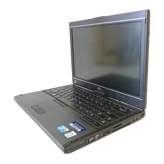
Dell Latitude XT2 Service Manual
Hide thumbs
Also See for Latitude XT2:
- User manual (138 pages) ,
- Setup manual (48 pages) ,
- Warnings and safety instructions (30 pages)
Table of Contents
Advertisement
Dell™ Latitude™ XT2 Service Manual
Tablet-PC
Features
Working on Your Tablet-PC
Adding and Replacing
Parts
Specifications
Diagnostics
System
BIOS
Notes, Cautions, and Warnings
NOTE:
A NOTE indicates important information that helps you make better use of your computer.
CAUTION:
A CAUTION indicates potential damage to hardware or loss of data if instructions are not followed.
WARNING:
A WARNING indicates a potential for property damage, personal injury, or death.
If you purchased a Dell™ n Series computer, any references in this document to Microsoft® Windows® operating systems are not applicable.
Information in this document is subject to change without notice.
© 2009 Dell Inc. All rights reserved.
Reproduction of this material in any manner whatsoever without the written permission of Dell Inc. is strictly forbidden.
Trademarks used in this text: Dell, the DELL logo, Latitude, TravelLite, Wi-Fi Catcher, and ExpressCharge, are trademarks of Dell Inc.; Intel, Pentium, Celeron a n d Core are registered
trademarks of Intel Corporation; Bluetooth is a registered trademark owned by Bluetooth SIG, Inc. and is used by Dell under license; TouchStrip is a trademark of Zvetco Biometrics,
LLC; Blu-ray Disc is a trademark of the Blu-ray Disc Association; Microsoft, Windows, Windows Server, MS-DOS, Aero, Windows Vista. and the Windows Vista start button are either
trademarks or registered trademarks of Microsoft Corporation in the United States and/or other countries.
Other trademarks and trade names may be used in this document to refer to either the entities claiming the marks and names or their products. Dell Inc. disclaims any
proprietary interest in trademarks and trade names other than its own.
Model PP12S
September 2009 Rev. A01
Advertisement
Table of Contents

Related Manuals for Dell Latitude XT2


Summary of Contents for Dell Latitude XT2
- Page 1 Reproduction of this material in any manner whatsoever without the written permission of Dell Inc. is strictly forbidden. Trademarks used in this text: Dell, the DELL logo, Latitude, TravelLite, Wi-Fi Catcher, and ExpressCharge, are trademarks of Dell Inc.; Intel, Pentium, Celeron a n d Core are registered trademarks of Intel Corporation;...
-
Page 2: Bios Screen Navigation Keystrokes
<F12> Menu Press <F12> when the Dell™ logo appears to initiate a one-time boot menu with a list of the valid boot devices for the system. Diagnostics and Enter Setup options are also included in this menu. The devices listed on the boot menu depend on the bootable devices in the system. This menu is useful when you are attempting to boot to a particular device or to bring up the diagnostics for the system. -
Page 3: Device Status Leds
If the computer is connected to an electrical outlet, the battery light operates as follows: Alternately blinking amber light and blue light — An unauthenticated or unsupported, non-Dell AC adapter is attached to your Tablet-PC. Alternately blinking amber light with steady blue light — Temporary battery failure with AC adapter present. - Page 4 same slot and test. Test the other slot with both modules. FLASH Memory is detected but has errors 3. Replace the memory 4. Replace the system board. 1. Reseat the modem. 2. Replace the modem. FLASH FLASH Modem Error 3. Replace the system board. 1.
-
Page 5: Digitizer Options Tab
Digitizer Options Tab Dell™ Latitude™ XT2 Service Manual The Digitizer Options tab is used for the following: Input mode selection Touch tuning Launching diagnostics Restoring default settings Input Mode The N-trig applet has 4 operating modes: Pen Only — In this mode, the stylus is the only device that can be used as the input device with the N-trig digitizer. Changing from Pen Only mode to any other mode is done by clicking with an active input device on the N-trig Applet icon in the system tray. - Page 6 Use this table to define the result codes. Digitizer Self Test Result Codes Code Test Error Details Symptoms Digitizer analog Digitizer is unable to initialize or read samples from analog processor. No pen or touch position is A-trigs connectivity processor fail reported.
- Page 7 Tablet-PC Features Dell™ Latitude™ XT2 Service Manual Tablet-PC Modes Tablet-PC Buttons Tablet-PC Interface Tablet-PC Settings Tablet-PC Pen Application Matrix ...
-
Page 8: Interaction Options Tab
Interaction Options Tab Dell™ Latitude™ XT2 Service Manual The Interaction Options tab controls the visual and sound effects that can modify the user experience while operating the system's various modes. Auto Mode Switching Graphical Indicator This section enables you to select a .gif file (image) to be displayed whenever an auto mode switching event is detected. You can select the event that will cause the graphical indicator to appear: Pen ®... -
Page 9: Application Matrix
Application Matrix Dell™ Latitude™ XT2 Service Manual The following matrix shows the gestures supported by the operating system and specific application software packages. Other applications may also respond to these gestures. Operating System Microsoft™ Windows Vista™ Microsoft Windows™ XP Application Family Application Name Pinch/Zoom Horizontal Scroll Vertical Scroll Pinch/Zoom Horizontal Scroll Vertical Scroll... - Page 10 Multi-Touch Gestures Feature Dell™ Latitude™ XT2 Service Manual Gestures Gestures are expressions made while touching the screen of your Tablet PC with two fingers. They are interpreted as user commands to the operating system or active application software. When the operating system recognizes a gesture, an icon confirming the gesture appears on the screen. This multi-touch update includes three gestures: a scroll gesture, a zoom gesture, and a two-finger double-tap gesture.
- Page 11 ...
-
Page 12: About Tab
About Tab Dell™ Latitude™ XT2 Service Manual The About tab is used to find information such as the driver version and firmware revision numbers. The firmware revision number can also be obtained by hovering your pointer over the N-trig Tablet Settings icon in the system tray. -
Page 13: Adding And Replacing Parts
Adding and Replacing Parts Dell™ Latitude™ XT2 User's Guide Main Battery Coin-Cell Battery Memory and Mini-Card Cover Grip Cover Memory Display Assembly Hard Drive Palm Rest Mini-Card Speaker System Board Internal Card With Bluetooth® Wireless Technology Heat Sink and Fan Assembly Hinge Cover Battery Latch Keyboard... -
Page 14: Calibrating The Pen
2. Click System ® Tablet Settings. 3. On the Dell Tablet Settings window, click Pen & Input then click Calibrate. 4. Follow the instructions on the screen. The calibration markers are displayed on the screen as plus signs (+). Tap the pen in the exact center of each of the calibration markers. -
Page 15: Specifications
Specifications Processors Audio System Information Display ExpressCard™ Keyboard SD™ Card Touch Pad Memory Battery Smart Card AC Adapter Ports and Connectors Fingerprint Reader Communications Physical Video Environmental NOTE: Offerings may vary by region. For more information regarding the configuration of your Tablet-PC, click Start (or Start in Windows XP)®... - Page 16 Interface speed 9600–115,200 bps EMV level Level 1 certified WHQL certification PC/SC Compatibility Compatible within a PKI environment Insert/eject cycles Certified for up to 100,000 cycles Ports and Connectors Audio microphone connector, stereo headphone/speakers connector IEEE 1394 4-pin serial connector E-dock Standard E-Dock connector for devices such as E- Dock advanced port replicators and expansion...
- Page 17 Maximum Resolutions 1280 x 800 at 262 K colors Operating angle 0° (closed) to 160° Refresh rate 60 Hz (40 Hz in All Day Battery Life (ADBL) mode) Viewing angles Horizontal 40/40° Vertical 15/30° Pixel pitch 0.204 Power consumption (panel with backlight, typical) 3.0 W (max) ...
- Page 18 Output current 3.3 A (maximum at 10ms pulse) 2.3 A (continuous) Output power 45 W or higher Rated output voltage 19.5 ±1.0 VDC Dimensions: Height 16 mm (0.63 inch) Width 63 mm (2.48 inches) Depth 88 mm (3.46 inches) Temperature range: Operating 0° to 40°C (32° to 104°F) ...
-
Page 19: Scroll Buttons
Each time you press and release the screen rotate button, the screen image rotates clockwise 90 degrees. QuickSet tablet settings button — Press this button to view and configure options for the Tablet-PC and the pen through Dell Control Point System Manager. -
Page 20: Windows Vista
Tablet-PC Interface Dell™ Latitude™ XT2 Service Manual Microsoft™ Windows Vista™ /XP Tablet-PC Interface Comparison Windows Vista Windows™ XP Windows Vista/XP Tablet-PC Interface Comparison Depending on the configuration you ordered, your Tablet-PC shipped with either the Windows Vista or Windows XP operating system. There are several differences in the Tablet PC-interfaces between the two. Listed below are the primary differences. -
Page 21: Pen Flicks
Working With Files You can open, delete, or move many files or folders at one time by selecting multiple items from a list. Using a tablet pen, hover over one item at a time and select the check box that appears to the left of each item. To turn check boxes on: 1. -
Page 22: Touch Usage
Touch Usage One of the key advantages of the Latitude XT2 Tablet PC is the ability to easily switch from pen input to touch input. When you use Touch Mode, a translucent image of a computer mouse, called the touch pointer, floats beneath your finger. The touch pointer has left and right mouse buttons that you can tap with your finger. -
Page 23: Tablet And Pen Settings
Lifting your finger from this point opens up the corresponding submenu. Tablet and Pen Settings Most of the settings for the tablet and pen are located in Control Panel under Tablet and Pen Settings. These are also accessed through Dell Control Point System Manager. -
Page 24: Notebook Mode
When you convert your Tablet-PC between notebook and tablet modes, the screen orientation of your Tablet-PC will automatically change according to the settings you have established in the Dell Control Point System Manager application or the Windows Vista Pen and Tablet settings application, most commonly from landscape (notebook mode) to portrait (tablet mode). -
Page 25: Installation
The N-trig Tablet Settings applet is built into the driver package. You can either install it directly from the ResourceCD or obtain the latest version from support.dell.com. Once the file has been extracted, an InstallShield Wizard will walk you through the process of installing the software. The appearance of the N-trig icon is an indication of a successful installation. -
Page 26: Removing The Memory And Mini-Card Cover
Replacing the Memory and Mini-Card Cover WARNING: Before working inside your Tablet-PC, read the safety information that shipped with your Tablet-PC. For additional safety best practices information, see the Regulatory Compliance Homepage at www.dell.com/regulatory_compliance. Removing the Memory and Mini-Card Cover 1. - Page 27 4. Tilt the cover towards the front of the Tablet-PC. 5. Lift the cover at an angle, and remove from the Tablet-PC. Replacing the Memory and Mini-Card Cover 1. Insert the tabs of the memory and mini-card cover into the slots of the base. 2.
- Page 28 4. Install the battery. See Replacing the Main Battery.
-
Page 29: Removing The Main Battery
Replacing the Main Battery WARNING: Before working inside your Tablet-PC, read the safety information that shipped with your Tablet-PC. For additional safety best practices information, see the Regulatory Compliance Homepage at www.dell.com/regulatory_compliance. Removing the Main Battery 1. Follow the procedures in Before Working Inside Your Tablet-P 2. - Page 30 3. Slide the battery out of the battery bay. 4. Remove the battery from the Tablet-PC.
-
Page 31: Replacing The Main Battery
Replacing the Main Battery 1. Slide the new battery into the battery bay. 2. Slide the battery until it locks into position. When properly seated, the battery is flush with the bottom edge of the computer and the battery-bay release latches are in the inward position as shown in Step 4 above. -
Page 32: Battery Latch
Dell™ Latitude™ XT2 Service Manual WARNING: Before working inside your Tablet-PC, read the safety information that shipped with your Tablet-PC. For additional safety best practices information, see the Regulatory Compliance Homepage at www.dell.com/regulatory_compliance. Removing the Battery Latch 1. Follow the procedures in Before Working Inside Your Tablet-P 2. - Page 33 15. Slide the latch assembly to the right. 16. Remove the right latch inside assembly from the bottom plastics. 17. Remove the right latch from the outside of the Tablet-PC.
- Page 34 18. Remove the screw securing the left latch assembly to the Tablet-PC. 18. Slide the inside latch assembly to the right and lift out of the bottom plastic.
- Page 35 19. Remove the left battery latch from the outside of the Tablet-PC.
- Page 37 Dell™ Latitude™ XT2 Service Manual WARNING: Before working inside your Tablet-PC, read the safety information that shipped with your Tablet-PC. For additional safety best practices information, see the Regulatory Compliance Homepage at www.dell.com/regulatory_compliance. Removing the BIOS Chip 1. Follow the procedures in Before Working Inside Your Tablet-P 2.
- Page 38 ...
-
Page 39: Removing The Internal Card With Bluetooth Wireless Technology
WARNING: Before working inside your Tablet-PC, read the safety information that shipped with your Tablet-PC. For additional safety best practices information, see the Regulatory Compliance Homepage at www.dell.com/regulatory_compliance. Removing the Internal Card With Bluetooth Wireless Technology 1. Follow the procedures in Before Working Inside Your Tablet-P 2. - Page 40 5. Disconnect the Bluetooth cable from the Bluetooth. 6. Remove the Bluetooth assembly from the Tablet-PC.
- Page 41 Replacing the Internal Card With Bluetooth Wireless Technology 1. Connect the Bluetooth cable to the new Bluetooth assembly. 2. Carefully slide the Bluetooth assembly into the bay. Note: Ensure that the Bluetooth cable does not disconnect from the Bluetooth assembly when sliding it into the bay. 3.
-
Page 42: Removing The Coin-Cell Battery
Replacing the Coin-Cell Battery WARNING: Before working inside your Tablet-PC, read the safety information that shipped with your Tablet-PC. For additional safety best practices information, see the Regulatory Compliance Homepage at www.dell.com/regulatory_compliance. Removing the Coin-Cell Battery 1. Follow the procedures in Before Working Inside Your Tablet-P 2. -
Page 43: Replacing The Coin-Cell Battery
Replacing the Coin-Cell Battery 1. Peel the backing from the new coin-cell battery. 2. Connect the coin-cell cable to the system board and press the coin-cell battery into place on the system board. See diagram in step 6 above for placement. - Page 44 Replacing the Grip Cover WARNING: Before working inside your Tablet-PC, read the safety information that shipped with your Tablet-PC. For additional safety best practices information, see the Regulatory Compliance Homepage at www.dell.com/regulatory_compliance. Removing the Grip Cover 1. Follow the procedures in Before Working Inside Your Tablet-P 2.
- Page 45 4. Slide the grip cover away from the Tablet-PC and remove. Replacing the Grip Cover 1. Slide the new grip cover onto the base of the Tablet-PC. 2. Attach the grip cover with the two grip cover screws. 3. Replace the battery. See Replacing the Main Battery.
-
Page 46: Removing The Hard Drive
Replacing the Hard Drive WARNING: Before working inside your Tablet-PC, read the safety information that shipped with your Tablet-PC. For additional safety best practices information, see the Regulatory Compliance Homepage at www.dell.com/regulatory_compliance. Removing the Hard Drive 1. Follow the procedures in Before Working Inside Your Tablet-P 2. - Page 47 4. Remove the hard drive bracket. 5. Slide the hard drive towards the edge of the Tablet-PC to disconnect from the system board.
- Page 48 6. Remove the hard drive from the Tablet-PC.
-
Page 49: Replacing The Hard Drive
Replacing the Hard Drive 1. Slide the new hard drive into position gently until the connector end fits into the system-board connector. 2. Secure the hard drive into place by replacing the hard drive bracket. Attach the bracket to the Tablet-PC with the four captive screws. 3. -
Page 50: Removing The Heat Sink And Fan Assembly
WARNING: Before working inside your Tablet-PC, read the safety information that shipped with your Tablet-PC. For additional safety best practices information, see the Regulatory Compliance Homepage at www.dell.com/regulatory_compliance. Removing the Heat Sink and Fan Assembly 1. Follow the procedures in Before Working Inside Your Tablet-P 2. - Page 51 16. Remove the top section of the heat sink assembly from the system board, then turn over the system board again. 17. Remove the bottom section of the heat sink assembly.
- Page 52 ...
-
Page 53: Removing The Keyboard
Replacing the Keyboard WARNING: Before working inside your Tablet-PC, read the safety information that shipped with your Tablet-PC. For additional safety best practices information, see the Regulatory Compliance Homepage at www.dell.com/regulatory_compliance. Removing the Keyboard 1. Follow the procedures in Before Working Inside Your Tablet-P 2. - Page 54 6. Release the zif connector on the touchpad connection. 7. Disconnect the touch pad cable.
- Page 55 8. Release the retaining clip on the keyboard connector. 9. Disconnect the keyboard cable from the system board.
- Page 56 10. Remove the keyboard from the Tablet-PC.
-
Page 57: Replacing The Keyboard
Replacing the Keyboard CAUTION: The key caps on the keyboard are fragile, easily dislodged, and time-consuming to replace. Exercise care when removing and handling the keyboard. 1. Holding the top of the keyboard slightly above the computer, connect the touchpad cable and the keyboard cable to the system board. 2. -
Page 58: Removing The Display Assembly
Dell™ Latitude™ XT2 Service Manual WARNING: Before working inside your Tablet-PC, read the safety information that shipped with your Tablet-PC. For additional safety best practices information, see the Regulatory Compliance Homepage at www.dell.com/regulatory_compliance. Removing the Display Assembly 1. Follow the procedures in Before Working Inside Your Tablet-P 2. - Page 59 7. From the top of the closed Tablet-PC, remove the two screws from the display assembly hinge grip. 8. From the inside of the Tablet-PC, disconnect the display assembly cable from the system board.
- Page 60 9. Unthread the antenna cables from the inside of the Tablet-PC. 10. Remove the five screws securing the display assembly to the Tablet-PC.
- Page 61 11. Lift the display assembly straight up to separate it from the Tablet-PC. 12. Remove the display assembly.
- Page 62 ...
-
Page 63: Removing The Hinge Cover
Before working inside your Tablet-PC, read the safety information that shipped with your Tablet-PC. For additional safety best practices information, see the Regulatory Compliance Homepage at www.dell.com/regulatory_compliance. CAUTION: To avoid electrostatic discharge, ground yourself by using a wrist grounding strap or by periodically touching a connector on the back panel of the computer. -
Page 64: Replacing The Hinge Cover
Replacing the Hinge Cover To replace the hinge cover, insert the left edge of the cover into the hinge cover slot and press from left to right until the cover snaps into place. -
Page 65: Removing A Memory Module
Replacing a Memory Module WARNING: Before working inside your Tablet-PC, read the safety information that shipped with your Tablet-PC. For additional safety best practices information, see the Regulatory Compliance Homepage at www.dell.com/regulatory_compliance. Removing a Memory Module 1. Follow the procedures in Before Working Inside Your Tablet-P 2. - Page 66 4. Remove the memory module from the Tablet-PC at an angle.
-
Page 67: Replacing A Memory Module
Replacing a Memory Module 1. Position the memory module into place by starting with the top side of the module and easing it down into place at an angle. 2. Ease the memory module down until it snaps into place between the retainer clips. 3. -
Page 68: Removing The Palm Rest
Dell™ Latitude™ XT2 Service Manual WARNING: Before working inside your Tablet-PC, read the safety information that shipped with your Tablet-PC. For additional safety best practices information, see the Regulatory Compliance Homepage at www.dell.com/regulatory_compliance. Removing the Palm Rest 1. Follow the procedures in Before Working Inside Your Tablet-P 2. - Page 69 8. Turn the Tablet-PC over and remove three screws securing the palm rest to the top of the Tablet-PC. 9. Remove the palm rest from the Tablet-PC.
- Page 70 ...
-
Page 71: Removing The Speaker
Dell™ Latitude™ XT2 Service Manual WARNING: Before working inside your Tablet-PC, read the safety information that shipped with your Tablet-PC. For additional safety best practices information, see the Regulatory Compliance Homepage at www.dell.com/regulatory_compliance. Removing the Speaker 1. Follow the procedures in Before Working Inside Your Tablet-P 2. - Page 72 15. Remove the speaker assembly from the Tablet-PC. ...
-
Page 73: Removing The System Board
Dell™ Latitude™ XT2 Service Manual WARNING: Before working inside your Tablet-PC, read the safety information that shipped with your Tablet-PC. For additional safety best practices information, see the Regulatory Compliance Homepage at www.dell.com/regulatory_compliance. Removing the System Board 1. Follow the procedures in Before Working Inside Your Tablet-P 2. - Page 74 15. Lift the retaining clip on the SATA cable. 16. Disconnect the SATA cable from the system board.
- Page 75 17. Lift the retaining clip on the wireless cable connector. 18. Disconnect the wireless cable connector from the system board.
- Page 76 19. Remove the one screw securing the system board to the bottom plastic. 20. Lift the system board up at an angle and remove from the Tablet-PC.
- Page 77 21. Disconnect the fan cable from the system board connector, then flip the system board over. 22. Loosen the four captive screws on the heat sink. 23. Remove the top section of the heat sink assembly from the system board, then turn the system board over again.
- Page 78 24. Remove the bottom section of the heat sink assembly. ...
-
Page 79: Removing The Mini-Card
Replacing the Mini-Card WARNING: Before working inside your Tablet-PC, read the safety information that shipped with your Tablet-PC. For additional safety best practices information, see the Regulatory Compliance Homepage at www.dell.com/regulatory_compliance. Removing the Mini-Card 1. Follow the procedures in Before Working Inside Your Tablet-P 2. - Page 80 5. Use your finger to gently pry the retaining clips back and release the mini-card. 6. Remove the mini-card from the Tablet-PC at an angle.
-
Page 81: Replacing The Mini-Card
Replacing the Mini-Card CAUTION: The connectors are keyed to ensure correct insertion. If you feel resistance, check the connectors on the card and on the system board, and realign the card. CAUTION: To avoid damage to the mini-card, ensure the cables are not under the card when you place the card. NOTE: The card slot will be marked by a WLAN silk-screen. - Page 82 NOTE: Ensure the cables are tucked into the cable channel. 5. Replace the memory and mini-card cover on the Tablet-PC. 6. Replace the battery (see Replacing the Main Battery).
- Page 83 Tablet-PC Modes Dell™ Latitude™ XT2 Service Manual User Modes Tablet Buttons Tablet-PC Interface Tablet Settings ...
-
Page 84: Before Working Inside Your Tablet-Pc
Before working inside your Tablet-PC, read the safety information that shipped with your Tablet-PC. For additional safety best practices information, see the Regulatory Compliance Homepage at www.dell.com/regulatory_compliance. CAUTION: Only a certified service technician should perform repairs on your Tablet-PC. Damage due to servicing that is not authorized by Dell is not covered by your warranty. CAUTION: To avoid electrostatic discharge, ground yourself by using a wrist grounding strap or by periodically touching an unpainted metal surface, such as a connector on the back of the computer. - Page 85 After you complete any replacement procedure, ensure you connect any external devices, cards, and cables before turning on your computer. CAUTION: To avoid damage to the Tablet-PC, use only the battery designed for this particular Dell computer. Do not use batteries designed for other Dell computers.