
Related Manuals for Gigabyte GA-870A-UD3


Summary of Contents for Gigabyte GA-870A-UD3
- Page 1 GA-870A-UD3 AM3 socket motherboard for ™ ™ AMD Phenom II processor/ AMD Athlon II processor User's Manual Rev. 3001 12ME-870AU3-3001R...
-
Page 3: Identifying Motherboard Revision
GIGABYTE's prior written permission. Documentation Classifications In order to assist in the use of this product, GIGABYTE provides the following types of documentations: For quick set-up of the product, read the Quick Installation Guide included with the product. -
Page 4: Table Of Contents
Table of Contents Box Contents ........................6 Optional Items .........................6 GA-870A-UD3 Motherboard Layout ................7 GA-870A-UD3 Motherboard Block Diagram ..............8 Chapter 1 Hardware Installation ..................9 Installation Precautions ..................9 1-2 Product Specifications ..................10 Installing the CPU and CPU Cooler ............... 13 1-3-1 Installing the CPU ....................13... - Page 5 SMART Recovery................... 72 Auto Green ..................... 73 Chapter 5 Appendix ......................75 5-1 Configuring SATA Hard Drive(s) ..............75 5-1-1 Configuring AMD SB850 SATA Controller .............75 5-1-2 Configuring GIGABYTE SATA2/JMicron JMB362 SATA Controller ......81 5-1-3 Making a SATA RAID/AHCI Driver Diskette ............87 5-1-4 Installing the SATA RAID/AHCI Driver and Operating System .......89 5-2 Configuring Audio Input and Output ...............
-
Page 6: Box Contents
Box Contents GA-870A-UD3 motherboard Motherboard driver disk User's Manual Quick Installation Guide One IDE cable Two SATA cables I/O Shield • The box contents above are for reference only and the actual items shall depend on the product package you obtain. -
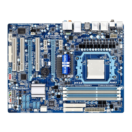
Page 7: Ga-870A-Ud3 Motherboard Layout
GA-870A-UD3 Motherboard Layout CPU_FAN KB_USB ATX_12V_2X4 RCA_SPDIF PWR_FAN Socket AM3 USB_1394_ESATA_2 USB_1394_ESATA_1 R_USB USB30_LAN Renesas D720200 GA-870A-UD3 JMicron JMB362 AUDIO F_AUDIO PCIEX1_1 AMD 870 Realtek PCIEX16 GIGABYTE RTL8111D/E SATA2 PCIEX1_2 GSATA2_7 GSATA2_6 SATA3_5 PCI1 CODEC AMD SB850 CLR_CMOS SYS_FAN2 SATA3_4... -
Page 8: Ga-870A-Ud3 Motherboard Block Diagram
GA-870A-UD3 Motherboard Block Diagram PCIe CLK CPU CLK+/- (200 MHz) (100 MHz) AM3 CPU DDR3 2000(O.C.)/1333/1066 MHz 1 PCI Express x16 Dual Channel Memory Hyper Transport 3.0 PCI Express x16 2 USB 3.0/2.0 2 SATA 3Gb/s PCIe CLK (100 MHz) -
Page 9: Chapter 1 Hardware Installation
Chapter 1 Hardware Installation Installation Precautions The motherboard contains numerous delicate electronic circuits and components which can become damaged as a result of electrostatic discharge (ESD). Prior to installation, carefully read the user's manual and follow these procedures: • Prior to installation, do not remove or break motherboard S/N (Serial Number) sticker or warranty sticker provided by your dealer. -
Page 10: Product Specifications
Dual channel memory architecture Support for DDR3 2000(O.C.)/1333/1066 MHz memory modules (Go to GIGABYTE's website for the latest supported memory speeds and memory modules.) Audio Realtek ALC892/889 codec High Definition Audio 2/4/5.1/7.1-channel Support for Dolby Home Theater ®... - Page 11 South Bridge: Up to 12 USB 2.0/1.1 ports (8 on the back panel, 4 via the USB brackets connected to the internal USB headers) Renesas D720200 chip: Up to 2 USB 3.0/2.0 ports on the back panel IEEE 1394 T.I.
- Page 12 BIOS 2 x 8 Mbit/16 Mbit flash Use of licensed AWARD BIOS Support for DualBIOS ™ PnP 1.0a, DMI 2.0, SM BIOS 2.4, ACPI 1.0b Unique Features Support for @BIOS Support for Q-Flash Support for Xpress BIOS Rescue Support for Download Center ...
-
Page 13: Installing The Cpu And Cpu Cooler
Read the following guidelines before you begin to install the CPU: • Make sure that the motherboard supports the CPU. (Go to GIGABYTE's website for the latest CPU support list.) • Always turn off the computer and unplug the power cord from the power outlet before installing the CPU to prevent hardware damage. - Page 14 B. Follow the steps below to correctly install the CPU into the motherboard CPU socket. • Before installing the CPU, make sure to turn off the computer and unplug the power cord from the power outlet to prevent damage to the CPU. • Do not force the CPU into the CPU socket. The CPU cannot fit in if oriented incorrectly. Adjust the CPU orientation if this occurs.
-
Page 15: Installing The Cpu Cooler
1-3-2 Installing the CPU Cooler Follow the steps below to correctly install the CPU cooler on the CPU. (The following procedure uses the GIGABYTE cooler as the example.) Step 1: Step 2: Place the CPU cooler on the CPU. Apply an even and thin layer of thermal grease on the surface of the installed CPU. -
Page 16: Installing The Memory
• Make sure that the motherboard supports the memory. It is recommended that memory of the same capacity, brand, speed, and chips be used. (Go to GIGABYTE's website for the latest supported memory speeds and memory modules.) • Always turn off the computer and unplug the power cord from the power outlet before installing the memory to prevent hardware damage. -
Page 17: Installing A Memory
1-4-2 Installing a Memory Before installing a memory module, make sure to turn off the computer and unplug the power cord from the power outlet to prevent damage to the memory module. DDR3 and DDR2 DIMMs are not compatible to each other or DDR DIMMs. Be sure to install DDR3 DIMMs on this motherboard. -
Page 18: Installing An Expansion Card
Installing an Expansion Card Read the following guidelines before you begin to install an expansion card: • Make sure the motherboard supports the expansion card. Carefully read the manual that came with your expansion card. • Always turn off the computer and unplug the power cord from the power outlet before installing an expansion card to prevent hardware damage. -
Page 19: Back Panel Connectors
Back Panel Connectors USB 2.0/1.1 Port The USB port supports the USB 2.0/1.1 specification. Use this port for USB devices such as a USB key- board/mouse, USB printer, USB flash drive and etc. PS/2 Keyboard or PS/2 Mouse Port Use this port to connect a PS/2 keyboard or mouse. Optical S/PDIF Out Connector This connector provides digital audio out to an external audio system that supports digital optical audio. Before using this feature, ensure that your audio system provides an optical digital audio in connector. - Page 20 USB 3.0/2.0 Port The USB 3.0 port supports the USB 3.0 specification and is compatible to the USB 2.0/1.1 specification. Use this port for USB devices such as a USB keyboard/mouse, USB printer, USB flash drive and etc. Center/Subwoofer Speaker Out Jack (Orange) Use this audio jack to connect center/subwoofer speakers in a 5.1/7.1-channel audio configuration. Rear Speaker Out Jack (Black) Use this audio jack to connect rear speakers in a 7.1-channel audio configuration. Side Speaker Out Jack (Gray) Use this audio jack to connect side speakers in a 4/5.1/7.1-channel audio configuration. Line In Jack (Blue) The default line in jack. Use this audio jack for line in devices such as an optical drive, walkman, etc. Line Out Jack (Green) The default line out jack.
-
Page 21: Internal Connectors
Internal Connectors ATX_12V_2X4 F_PANEL F_AUDIO CPU_FAN CD_IN SYS_FAN1/2 SPDIF_IN PWR_FAN SPDIF_OUT F_USB1/F_USB2 F_1394 SATA3_0/1/2/3/4/5 COMA GSATA2_6/7 CLR_CMOS Read the following guidelines before connecting external devices: • First make sure your devices are compliant with the connectors you wish to connect. • Before installing the devices, be sure to turn off the devices and your computer. - Page 22 1/2) ATX_12V_2X4/ATX (2x4 12V Power Connector and 2x12 Main Power Connector) With the use of the power connector, the power supply can supply enough stable power to all the com- ponents on the motherboard. Before connecting the power connector, first make sure the power supply is turned off and all devices are properly installed. The power connector possesses a foolproof design. Connect the power supply cable to the power connector in the correct orientation.
- Page 23 3/4/5) CPU_FAN/SYS_FAN1/SYS_FAN2/PWR_FAN (Fan Headers) The motherboard has a 4-pin CPU fan header (CPU_FAN), a 4-pin (SYS_FAN1) and a 3-pin (SYS_ FAN2) system fan headers, and a 3-pin power fan header (PWR_FAN). Most fan headers possess a foolproof insertion design. When connecting a fan cable, be sure to connect it in the correct orientation (the black connector wire is the ground wire).
- Page 24 7) IDE (IDE Connector) The IDE connector supports up to two IDE devices such as hard drives and optical drives. Before attach- ing the IDE cable, locate the foolproof groove on the connector. If you wish to connect two IDE devices, remember to set the jumpers and the cabling according to the role of the IDE devices (for example, master or slave). (For information about configuring master/slave settings for the IDE devices, read the instructions from the device manufacturers.)
-
Page 25: Bat Battery
9) GSATA2_6/7 (SATA 3Gb/s Connectors, Controlled by GIGABYTE SATA2) The SATA connectors conform to SATA 3Gb/s standard and are compatible with SATA 1.5Gb/s standard. Each SATA connector supports a single SATA device. The GIGABYTE SATA2 supports RAID 0 and RAID 1. Refer to Chapter 5, "Configuring SATA Hard Drive(s)," for instructions on configuring a RAID array. -
Page 26: F_Panel Front Panel Header
11) F_PANEL (Front Panel Header) Connect the power switch, reset switch, speaker, chassis intrusion switch/sensor and system status indicator on the chassis to this header according to the pin assignments below. Note the positive and negative pins before connecting the cables. Message/Power/ Power Speaker... -
Page 27: Front Panel Audio Header
12) F_AUDIO (Front Panel Audio Header) The front panel audio header supports Intel High Definition audio (HD) and AC'97 audio. You may connect your chassis front panel audio module to this header. Make sure the wire assignments of the module con- nector match the pin assignments of the motherboard header. Incorrect connection between the module connector and the motherboard header will make the device unable to work or even damage it. For HD Front Panel Audio: For AC'97 Front Panel Audio: Pin No. Definition... - Page 28 14) SPDIF_IN (S/PDIF In Header) This header supports digital S/PDIF In and can connect to an audio device that supports digital audio out via an optional S/PDIF In cable. For purchasing the optional S/PDIF In cable, please contact the local dealer.
-
Page 29: F_1394 Ieee 1394A Header
16) F_USB1/F_USB2 (USB Headers) The headers conform to USB 2.0/1.1 specification. Each USB header can provide two USB ports via an optional USB bracket. For purchasing the optional USB bracket, please contact the local dealer. Pin No. Definition Power (5V) Power (5V) USB DX- USB DY- USB DX+ USB DY+ No Pin When the system is in S4/S5 mode, only the USB ports routed to the F_USB1 header can sup- port the ON/OFF Charge function. - Page 30 18) COMA (Serial Port Header) The COM header can provide one serial port via an optional COM port cable. For purchasing the op- tional COM port cable, please contact the local dealer. Pin No. Definition NDCD- NSIN NSOUT DEBUG NDTR- PORT NDSR- NRTS- NCTS-...
-
Page 31: Clear Cmos Jumper
20) CLR_CMOS (Clearing CMOS Jumper) Use this jumper to clear the CMOS values (e.g. date information and BIOS configurations) and reset the CMOS values to factory defaults. To clear the CMOS values, place a jumper cap on the two pins to tem- porarily short the two pins or use a metal object like a screwdriver to touch the two pins for a few seconds. Open: Normal Short: Clear CMOS Values •... - Page 32 Hardware Installation - 32 -...
-
Page 33: Chapter 2 Bios Setup
To see more advanced BIOS Setup menu options, you can press <Ctrl> + <F1> in the main menu of the BIOS Setup program. To upgrade the BIOS, use either the GIGABYTE Q-Flash or @BIOS utility. Q-Flash allows the user to quickly and easily upgrade or back up BIOS without entering the operating •... -
Page 34: Startup Screen
A. The LOGO Screen (Default) Function Keys B. The POST Screen Award Modular BIOS v6.00PG Copyright (C) 1984-2010, Award Software, Inc. AMD 870 BIOS for GA-870A-UD3 D1 Motherboard Model BIOS Version Function Keys <DEL>: BIOS Setup <F9>: XpressRecovery2 <F12>: Boot Menu <End>: Qflash... -
Page 35: The Main Menu
The Main Menu Once you enter the BIOS Setup program, the Main Menu (as shown below) appears on the screen. Use ar- row keys to move among the items and press <Enter> to accept or enter a sub-menu. (Sample BIOS Version: D1) CMOS Setup Utility-Copyright (C) 1984-2010 Award Software MB Intelligent Tweaker(M.I.T.) Load Fail-Safe Defaults... -
Page 36: Integrated Peripherals
The Functions of the <F11> and <F12> keys (For the Main Menu Only) F11: Save CMOS to BIOS This function allows you to save the current BIOS settings to a profile. You can create up to 8 profiles (Profile 1-8) and name each profile. First enter the profile name (to erase the default profile name, use the SPACE key) and then press <Enter> to complete. F12: Load CMOS from BIOS If your system becomes unstable and you have loaded the BIOS default settings, you can use this function to load the BIOS settings from a profile created before, without the hassles of reconfiguring the BIOS settings. First select the profile you wish to load, then press <Enter> to complete. -
Page 37: Mb Intelligent Tweaker(M.i.t.)
MB Intelligent Tweaker(M.I.T.) CMOS Setup Utility-Copyright (C) 1984-2010 Award Software MB Intelligent Tweaker(M.I.T.) Item Help CPU Clock Ratio [Auto] 2800Mhz Menu Level CPU NorthBridge Freq. [Auto] 2000Mhz CPU Host Clock Control [Auto] x CPU Frequency(MHz) PCIE Clock(MHz) [Auto] PCIe Spread Spectrum [Disabled] HT Link Frequency [Auto]... - Page 38 PCIe Spread Spectrum Enables or disables PCIe Spread Spectrum. (Default: Disabled) HT Link Frequency Allows you to manually set the frequency for the HT Link between the CPU and chipset. Auto BIOS will automatically adjust the HT Link Frequency. (Default) x1~x10 Sets HT Link Frequency to x1~x10 (200 MHz~2.0 GHz).
- Page 39 RAS to CAS R/W Delay Options are: Auto (default), 5T~12T. Row Precharge Time Options are: Auto (default), 5T~12T. Minimum RAS Active Time Options are: Auto (default), 15T~30T. 1T/2T Command Timing Options are: Auto (default), 1T, 2T. TwTr Command Delay Options are: Auto (default), 4T~7T. Trfc0 for DIMM1 Options are: Auto (default), 90ns, 110ns, 160ns, 300ns, 350ns.
- Page 40 ******** System Voltage Optimized ******** System Voltage Control Determines whether to manually set the system voltages. Auto lets the BIOS automatically set the system voltages as required. Manual allows all voltage control items below to be configurable. (Default: Auto) DRAM Voltage Control Allows you to set the memory voltage. Normal Supplies the memory voltage as required.
-
Page 41: Standard Cmos Features
Standard CMOS Features CMOS Setup Utility-Copyright (C) 1984-2010 Award Software Standard CMOS Features Item Help Date (mm:dd:yy) Mon, Dec 20 2010 Menu Level Time (hh:mm:ss) 22:31:24 IDE Channel 0 Master [None] IDE Channel 0 Slave [None] IDE Channel 1 Master [None] ... - Page 42 Lets the BIOS automatically detect IDE/SATA devices during the POST. (Default) • Auto If no IDE/SATA devices are used, set this item to None so the system will skip • None the detection of the device during the POST for faster system startup. Access Mode Sets the hard drive access mode.
-
Page 43: Advanced Bios Features
Advanced BIOS Features CMOS Setup Utility-Copyright (C) 1984-2010 Award Software Advanced BIOS Features Item Help AMD C1E Support [Auto] (Note) Menu Level Virtualization [Disabled] AMD K8 Cool&Quiet control [Auto] CPU Unlock (Note) [Disabled] CPU core Control [Auto] x CPU core 0 Enabled x CPU core 1 Enabled... - Page 44 (Default: Disabled) Full Screen LOGO Show Allows you to determine whether to display the GIGABYTE Logo at system startup. Disabled displays normal POST message. (Default: Enabled) Backup BIOS Image to HDD Allows the system to copy the BIOS image file to the hard drive. If the system BIOS is corrupted, it will...
-
Page 45: Integrated Peripherals
Integrated Peripherals CMOS Setup Utility-Copyright (C) 1984-2010 Award Software Integrated Peripherals Item Help OnChip SATA Controller [Enabled] Menu Level OnChip SATA Type [Native IDE] x OnChip SATA Port4/5 Type x OnChip SATA RAID5 Support Enabled OnChip SATA3.0 Suuport [Enabled] x OnChip SATA Port as ESP Press Enter Onboard GSATA/IDE Ctrl [Enabled]... - Page 46 Port4/5 is set to as SATA Type. Enabled will speed up the hot plug detection of the connected SATA device. (Default: Disabled) Onboard GSATA/IDE Ctrl (GIGABYTE SATA2 Chip, GSATA2_6/7 Connectors) Enables or disables the SATA controller integrated in the GIGABYTE SATA2 chip. (Default: Enabled) Onboard GSATA/IDE Mode (GIGABYTE SATA2 Chip, GSATA2_6/7 Connectors) Allows you to decide whether to configure the SATA controller integrated in the GIGABYTE SATA2 chip to AHCI mode.
- Page 47 Onboard ESATA controller (JMicron JMB362 Chip, eSATA Connectors on the Back Panel) Enables or disables the SATA controller integrated in the JMicron JMB362 chip. (Default: Enabled) Onboard ESATA Mode (JMicron JMB362 Chip, eSATA Connectors on the Back Panel) Enables or disables RAID for the SATA controller integrated in the JMicron JMB362 chip or configures the SATA controller to AHCI mode. IDE Disables RAID for the SATA controller and configures the SATA controller to IDE mode.
- Page 48 When a Cable Problem Occurs... If a cable problem occurs on a specified pair of wires, the Status field will show Short and then length shown will be the approximate distance to the fault or short. Example: Part1-2 Status = Short / Length Explanation: A fault or short might occur at about 2m on Part 1-2. Note: Part 4-5 and Part 7-8 are not used in a 10/100 Mbps environment, so their Status fields will show Open, and the length shown is the approximate length of the attached LAN cable.
-
Page 49: Power Management Setup
Power Management Setup CMOS Setup Utility-Copyright (C) 1984-2010 Award Software Power Management Setup Item Help ACPI Suspend Type [S3(STR)] Menu Level Soft-Off by Power button [Instant-off] USB Wake Up from S3 [Enabled] Modem Ring Resume [Disabled] PME Event Wake Up [Enabled] HPET Support [Enabled]... - Page 50 HPET Support (Note) Enables or disables High Precision Event Timer (HPET) for Windows 7/Vista operating system. (Default: Enabled) Power On By Mouse Allows the system to be turned on by a PS/2 mouse wake-up event. Note: To use this function, you need an ATX power supply providing at least 1A on the +5VSB lead. Disabled Disables this function.
-
Page 51: Pc Health Status
PC Health Status CMOS Setup Utility-Copyright (C) 1984-2010 Award Software PC Health Status Item Help Hardware Thermal Control [Enabled] Menu Level Reset Case Open Status [Disabled] Case Opened Vcore 1.364V DDR3 1.5V 1.536V +3.3V 3.280V +12V 12.048V Current System Temperature Current CPU Temperature Current CPU FAN Speed 1962 RPM... - Page 52 Current Voltage(V) Vcore/DDR3 1.5V/+3.3V/+12V Displays the current system voltages. Current System/CPU Temperature Displays current system/CPU temperature. Current CPU/SYSTEM/POWER FAN Speed (RPM) Displays current CPU/system/power fan speed. CPU Warning Temperature Sets the warning threshold for CPU temperature. When CPU temperature exceeds the threshold, BIOS will emit warning sound.
-
Page 53: Load Fail-Safe Defaults
Load Fail-Safe Defaults CMOS Setup Utility-Copyright (C) 1984-2010 Award Software MB Intelligent Tweaker(M.I.T.) Load Fail-Safe Defaults Standard CMOS Features Load Optimized Defaults Advanced BIOS Features Set Supervisor Password Integrated Peripherals Set User Password Power Management Setup Save &... -
Page 54: Set Supervisor/User Password
2-11 Set Supervisor/User Password CMOS Setup Utility-Copyright (C) 1984-2010 Award Software MB Intelligent Tweaker(M.I.T.) Load Fail-Safe Defaults Standard CMOS Features Load Optimized Defaults Advanced BIOS Features Set Supervisor Password Integrated Peripherals Set User Password Power Management Setup Save &... -
Page 55: Save & Exit Setup
2-12 Save & Exit Setup CMOS Setup Utility-Copyright (C) 1984-2010 Award Software MB Intelligent Tweaker(M.I.T.) Load Fail-Safe Defaults Standard CMOS Features Load Optimized Defaults Save to CMOS and EXIT (Y/N)? Y Advanced BIOS Features Set Supervisor Password Integrated Peripherals Set User Password ... - Page 56 BIOS Setup - 56 -...
-
Page 57: Chapter 3 Drivers Installation
• After "Xpress Install" installs all of the drivers, a dialog box will appear asking whether to install new GIGABYTE utilities. Click Yes to automatically install the utilities. Or click No if you want to manually select the utilities to install on the Application Software page later. -
Page 58: Application Software
Application Software This page displays all the utilities and applications that GIGABYTE develops and some free software. You can click the Install button on the right of an item to install it. Technical Manuals This page provides GIGABYTE's application guides, content descriptions for this driver disk, and the mother- board manuals. -
Page 59: Contact
Contact For the detailed contact information of the GIGABYTE Taiwan headquarter or worldwide branch offices, click the URL on this page to link to the GIGABYTE website. System This page provides the basic system information. - 59 - Drivers Installation... -
Page 60: Download Center
The latest version of the BIOS, drivers, or applications will be displayed. New Utilities This page provides a quick link to GIGABYTE's lately developed utilities for users to install. You can click the Install button on the right of an item to install it. -
Page 61: Chapter 4 Unique Features
Chapter 4 Unique Features Xpress Recovery2 Xpress Recovery2 is a utility that allows you to quickly compress and back up your system data and perform restoration of it. Supporting NTFS, FAT32, and FAT16 file systems, Xpress Recovery2 can back up data on PATA and SATA hard drives and restore it. - Page 62 Step 3: Step 4: When partitioning your hard drive, make sure to After the operating system is installed, right-click leave unallocated space (10 GB or more is recom- the Computer icon on your desktop and select mended; actual size requirements vary, depending Manage.
- Page 63 D. Using the Restore Function in Xpress Recovery2 Select RESTORE to restore the backup to your hard drive in case the system breaks down. The RESTORE option will not be present if no backup is created before. E. Removing the Backup Step 1: Step 2: If you wish to remove the backup file, select...
-
Page 64: Bios Update Utilities
BIOS Update Utilities GIGABYTE motherboards provide two unique BIOS update tools, Q-Flash and @BIOS . GIGABYTE ™ ™ Q-Flash and @BIOS are easy-to-use and allow you to update the BIOS without the need to enter MS-DOS mode. Additionally, this motherboard features the DualBIOS design, which enhances protection for the ™... - Page 65 B. Updating the BIOS When updating the BIOS, choose the location where the BIOS file is saved. The following procedure as- sumes that you save the BIOS file to a USB flash drive. Step 1: 1. Insert the USB flash drive containing the BIOS file into the computer. In the main menu of Q-Flash, use the up or down arrow key to select Update BIOS from Drive and press <Enter>. •...
- Page 66 Step 4: Press <Esc> and then <Enter> to exit Q-Flash and reboot the system. As the system boots, you should see the new BIOS version is present on the POST screen. Step 5: During the POST, press <Delete> to enter BIOS Setup. Select Load Optimized Defaults and press <Enter> to load BIOS defaults.
-
Page 67: Updating The Bios With The @Bios Utility
BIOS or a system that is unable to start. Do not use the G.O.M. (GIGABYTE Online Management) function when using @BIOS. GIGABYTE product warranty does not cover any BIOS damage or system failure resulting from an inad- equate BIOS flashing. -
Page 68: Easytune 6
EasyTune 6 GIGABYTE's EasyTune 6 is a simple and easy-to-use interface that allows users to fine-tune their system settings or do overclock/overvoltage in Windows environment. The user-friendly EasyTune 6 interface also includes tabbed pages for CPU and memory information, letting users read their system-related information without the need to install additional software. The EasyTune 6 Interface... -
Page 69: Easy Energy Saver
The Easy Energy Saver Interface A. Meter Mode In Meter Mode, GIGABYTE Easy Energy Saver shows how much power they have saved in a set period of time. Meter Mode - Button Information Table Button Description Easy Energy Saver On/Off Switch (Default: Off) - Page 70 B. Total Mode In Total Mode, users are able to see how much total power savings they have accumulated in a set period of time since activating Easy Energy Saver for the first time (Note 3) Total Mode - Button Information Table Button Description Easy Energy Saver On/Off Switch (Default: Off) Dynamic CPU Frequency Function On/Off Switch (Default: Off) (Note 1) CPU Throttling Display...
-
Page 71: Q-Share
Q-Share, you are able to share your data with computers on the same network, making full use of Internet resources. Directions for using Q-Share After installing Q-Share from the motherboard driver disk, go to Start>All Programs>GIGABYTE>Q-Share. exe to launch the Q-Share tool. Find the Q-Share icon in the notification area and right-click on this icon to configure the data sharing settings. -
Page 72: Smart Recovery
SMART Recovery With SMART Recovery, users can quickly create backups of changed data files or copy files from a spe- (Note 1) cific backup on PATA and SATA hard drives (partitioned on NTFS file system) in Windows Vista. Instructions: In the main menu, click the Config button to open the Smart Recov- ery Preference dialog box. The Smart Recovery Preference dialog box: Button Function Enable Enables automatic daily backup (Note 2) Schedule Sets a daily backup schedule Capacity... -
Page 73: Auto Green
Auto Green Auto Green is an easy-to-use tool that provides users with simple options to enable system power savings via a Bluetooth cell phone. When the phone is out of the range of the computer's Bluetooth receiver, the sys- tem will enter the specified power saving mode. The Configuration dialog box: First, you have to set your Bluetooth cell phone as a portable key. - Page 74 Unique Features - 74 -...
-
Page 75: Chapter 5 Appendix
Chapter 5 Appendix Configuring SATA Hard Drive(s) To configure SATA hard drive(s), follow the steps below: A. Install SATA hard drive(s) in your computer. B. Configure SATA controller mode in BIOS Setup. C. Configure a RAID array in RAID BIOS. (Note 1) D. Make a floppy disk containing the SATA RAID/AHCI driver for Windows XP. (Note 2) E. Install the SATA RAID/AHCI driver and operating system. - Page 76 B. Configuring SATA controller mode in BIOS Setup Make sure to configure the SATA controller mode correctly in system BIOS Setup. Step 1: Turn on your computer and press <Delete> to enter BIOS Setup during the POST (Power-On Self-Test). Make sure OnChip SATA Controller is enabled. To enable RAID for the SATA3_0/1/2/3 connectors, set On- Chip SATA Type to RAID.
- Page 77 C. Configuring RAID set in RAID BIOS Enter the RAID BIOS setup utility to configure a RAID array. Skip this step and proceed with the installation of Windows operating system for a non-RAID configuration. Step 1: After the POST memory test begins and before the operating system boot begins, look for a message which says "Press <Ctrl-F> to enter RAID Option ROM Utility" (Figure 2). Press <Ctrl> + <F> to enter the RAID BIOS setup utility.
- Page 78 Option ROM Utility (c) 2009 Advanced Micro Devices, Inc. [ LD Define Menu ] LD No LD Name RAID Mode LD 1 Logical Drive 1 RAID 0 Stripe Block: 64 KB Fast Init: Gigabyte Boundary: Cache Mode: WriteThru [ Drives Assignments ] Port:ID Drive Model Capabilities Capacity (GB) Assignment 01:00 WDC WD800JD-22LSA0 SATA 3G 79.89...
- Page 79 In the following procedure, we'll create RAID 0 as an example. 1. Under the RAID Mode section, press the <SPACE> key to select RAID 0. 2. Set the Stripe Block size. 64 KB is the default. 3. Under the Drives Assignments section, press the up or down arrow key to highlight a drive. 4.
- Page 80 View Drive Assignments The View Drive Assignments option in the Main Menu displays whether the attached hard drives are as- signed to a disk array or are unassigned. Under the Assignment column, drives are labeled with their as- signed disk array or shown as Free if unassigned. Option ROM Utility (c) 2009 Advanced Micro Devices, Inc.
-
Page 81: Configuring Gigabyte Sata2/Jmicron Jmb362 Sata Controller
5-1-2 Configuring GIGABYTE SATA2/JMicron JMB362 SATA Controller A. Installing SATA hard drive(s) in your computer Attach one end of the SATA signal cable to the rear of the SATA hard drive and the other end to available SATA port on the motherboard. See the table below for the SATA controllers and their corresponding SATA ports. - Page 82 After the POST memory test begins and before the operating system boot begins, look for a message which says "Press <Ctrl-G> to enter RAID Setup Utility" (Figure 2). Press <Ctrl> + <G> to enter the RAID setup util- ity. GIGABYTE Technology Corp. PCI Express to SATAII Host Controller ROM v1.07.16G Copyright (C) 2005-2009 GIGABYTE Technology. HDD0...
- Page 83 In the main screen, press <Enter> on the Create RAID Disk Drive item. Then the Create New RAID screen appears (Figure 4). Gigabyte Technology Corp. RAID Setup Utility v1.07.16G [ Create New RAID ] [ Hard Disk Drive List ]...
- Page 84 4. Set Block Size (RAID 0 only): Under the Block item, use the up or down arrow key to select the stripe block size (Figure 6), ranging from 4 KB to 128 KB. Press <Enter>. Gigabyte Technology Corp. RAID Setup Utility v1.07.16G [ Create New RAID ]...
- Page 85 When finished, the new RAID array will be displayed in the RAID Disk Drive List block (Figure 8). Gigabyte Technology Corp. RAID Setup Utility v1.07.16G [ Main Menu ] [ Hard Disk Drive List ] Create RAID Disk Drive Model Name Capacity Type/Status Delete RAID Disk Drive HDD0: ST3120026AS 120 GB...
- Page 86 7. Save and Exit Setup: After configuring the RAID array, select the Save And Exit Setup item in the main screen to save your settings before exiting the RAID BIOS utility, then press <Y> (Figure 10). Gigabyte Technology Corp. RAID Setup Utility v1.07.16G [ Main Menu ] [ Hard Disk Drive List ]...
-
Page 87: Making A Sata Raid/Ahci Driver Diskette
3: At the A:\> prompt, type the following command. Press <Enter> after the command: • For the AMD SB850, type (Figure 1): (Note 1) A:\>copy d:\bootdrv\SB8xx\x86\*.* • For the GIGABYTE SATA2/JMicron JMB362, type (Figure 2): (Note 2) A:\>copy d:\bootdrv\gsata\32bit\*.* Figure 1 Figure 2 (Note 1) Type the driver directory based on the operating system to be installed. - Page 88 Figure 4, • For the AMD SB850, select 3) ATi AHCI/RAID Driver for XP for Windows XP operating system. • For the GIGABYTE SATA2/JMicron JMB362, select 1) GIGABYTE GSATA driver for 32bit system for Windows 32-bit operating system. Your system will then automatically copy the driver files to the floppy disk. Press any key to exit when finished.
-
Page 89: Installing The Sata Raid/Ahci Driver And Operating System
5-1-4 Installing the SATA RAID/AHCI Driver and Operating System With the SATA RAID/AHCI driver diskette and correct BIOS settings, you are ready to install Windows Vista/ XP onto your hard drive(s). The followings are examples of Windows XP and Vista installation. A. - Page 90 For the GIGABYTE SATA2/JMicron JMB362: Insert the floppy disk containing the SATA RAID/AHCI driver and press <S>. Then a controller menu similar to Figure 3 below will appear. Select RAID/AHCI Driver for GIGABYTE GBB36X Controller (x32) and press <Enter>. Windows Setup You have chosen to configure a SCSI Adapter for use with Windows, using a device support disk provided by an adapter manufacturer. Select the SCSI Adapter you want from the following list, or press ESC to return to the previous screen.
- Page 91 B. Installing Windows Vista The procedure below assumes that only one RAID array exists in your system. For the AMD SB850: Step 1: Restart your system to boot from the Windows Vista setup disk and perform standard OS installation steps. When a screen similar to that below appears (RAID hard drive will not be detected at this stage), select Load Driver (Figure 4).
- Page 92 Step 3: When a screen as shown in Figure 6 appears, select AMD AHCI Compatible RAID Controller and click Next. Figure 6 Step 4: After the driver is loaded, the RAID drive will appear. Select the RAID drive and then click Next to continue the OS installation (Figure 7).
- Page 93 For the GIGABYTE SATA2/JMicron JMB362: Step 1: Restart your system to boot from the Windows Vista setup disk and perform standard OS installation steps. When a screen similar to that below appears (RAID/AHCI hard drive(s) will not be detected at this stage), select Load Driver (Figure 8).
- Page 94 Step 3: When a screen as shown in Figure 10 appears, select GIGABYTE GBB36X Controller and click Next. Figure 10 Step 4: After the driver is loaded, select the RAID/AHCI drive(s) where you want to install the operating system and then click Next to continue the OS installation (Figure 11).
- Page 95 Rebuilding an Array: Rebuilding is the process of restoring data to a hard drive from other drives in the array. Rebuilding applies only to fault-tolerant arrays such as RAID 1, RAID 5, or RAID 10. To replace the old drive, make sure to use a new drive of equal or greater capacity.
- Page 96 Turn off your computer and replace the failed hard drive with a new one. Use either the RAID setup utility or the GIGABYTE RAID CONFIGURER utility in the operating system to perform the rebuild. • Rebuilding with the RAID setup utility Step 1: When the message "Press <Ctrl-G>...
- Page 97 • Rebuilding in the operating system Make sure the GIGABYTE SATA2/JMicron JMB362 SATA controller driver has been installed from the moth- erboard driver disk. Launch the GIGABYTE RAID CONFIGURER from All Programs in the Start menu. Step 2: When the Rebuilding RAID Wizard appears, click Next.
-
Page 98: Configuring Audio Input And Output
Configuring Audio Input and Output 5-2-1 Configuring 2/4/5.1/7.1-Channel Audio The motherboard provides six audio jacks on the back panel which support 2/4/5.1/7.1-channel audio. (Note) The picture to the right shows the default audio jack Center/Subwoofer Line In Speaker Out assignments. Rear Speaker Out Front Speaker Out The integrated HD (High Definition) audio provides... - Page 99 Step 2: Connect an audio device to an audio jack. The The cur- rent connected device is dialog box appears. Select the device according to the type of device you connect. Then click OK. Step 3: On the Speakers screen, click the Speaker Configura- tion tab.
-
Page 100: Configuring S/Pdif In/Out
5-2-2 Configuring S/PDIF In/Out A. S/PDIF In The S/PDIF In cable (optional) allows you to input digital audio signals to the computer for audio processing. S/PDIF In Cable Optical Coaxial S/PDIF In S/PDIF In 1. Installing the S/PDIF In Cable: Step 1: Step 2: First, attach the connector at the end of the cable... - Page 101 B. S/PDIF Out The S/PDIF Out jacks can transmit audio signals to an external decoder for decoding to get the best audio quality. 1. Connecting a S/PDIF Out Cable: S/PDIF Coaxial Cable S/PDIF Optical Cable Connect a S/PDIF coaxial cable or a S/PDIF optical cable (either one) to an external decoder for transmitting the S/PDIF digital audio signals.
-
Page 102: Enabling The Dolby Home Theater Function
5-2-3 Enabling the Dolby Home Theater Function Before Dolby Home Theater is enabled, you get only 2-channel playback output (from the front speakers) when playing 2-channel stereo sources. You must play 4-, 5.1-, or 7.1- chan- nel content to get 4-, 5.1-, or 7.1- channel audio effects. With Dolby Home Theater enabled, 2-channel stereo content will be transformed into multi-channel audio, creating a virtual sur- round sound environment (Note) -
Page 103: Configuring Microphone Recording
5-2-4 Configuring Microphone Recording Step 1: After installing the audio driver, the HD Audio Manager icon will appear in the notification area. Double-click the icon to access the HD Audio Manager. Step 2: Connect your microphone to the Mic in jack (pink) on the back panel or the Mic in jack (pink) on the front panel. Then configure the jack for microphone function- ality. - Page 104 Step 4: To raise the recording and playback volume for the microphone, click the Microphone Boost icon the right of the Recording Volume slider and set the Microphone Boost level. Step 5: After completing the settings above, click Start, point to All Programs, point to Accessories, and then click Sound Recorder to begin the sound recording.
-
Page 105: Using The Sound Recorder
Step 3: When the Stereo Mix item appears, right-click on this item and select Enable. Then set it as the default de- vice. Step 4: Now you can access the HD Audio Manager to config- ure Stereo Mix and use Sound Recorder to record the sound. -
Page 106: Troubleshooting
Troubleshooting 5-3-1 Frequently Asked Questions To read more FAQs for your motherboard, please go to the Support & Downloads\FAQ page on GIGABYTE's website. Q: In the BIOS Setup program, why are some BIOS options missing? A: Some advanced options are hidden in the BIOS Setup program. Press <Delete> to enter BIOS Setup during the POST. In the Main Menu, press <Ctrl>+<F1>... -
Page 107: Troubleshooting Procedure
5-3-2 Troubleshooting Procedure If you encounter any troubles during system startup, follow the troubleshooting procedure below to solve the problem. START Turn off the power. Remove all peripherals, connecting cables, and power cord etc. Make sure the motherboard does not short-circuit with the chassis or Isolate the short circuit. - Page 108 The power supply, CPU or When the computer is turned on, is the CPU cooler running? CPU socket might fail. The problem is verified and solved. The graphics card, expansion slot, or monitor Check if there is display on your monitor. might fail. The problem is verified and solved. Turn off the computer. Plug in the keyboard and mouse and restart the computer.
- Page 109 - 109 - Appendix...
- Page 110 Appendix - 110 -...
- Page 111 Web address: http://latam.giga-byte.com TEL: +86-24-83992901 • Giga-Byte SINGAPORE PTE. LTD. - Singapore FAX: +86-24-83992909 WEB address : http://www.gigabyte.sg • GIGABYTE TECHNOLOGY (INDIA) LIMITED - India • Thailand WEB address : http://www.gigabyte.in WEB address : http://th.giga-byte.com • Saudi Arabia • Vietnam WEB address : http://www.gigabyte.com.sa...
- Page 112 WEB address : http://www.gigabyte.com.gr WEB address : http://www.gigabyte.kz • Czech Republic You may go to the GIGABYTE website, select your language WEB address : http://www.gigabyte.cz in the language list on the top right corner of the website. • GIGABYTE Global Service System...