
Related Manuals for Gigabyte GA-8I915P Duo


Summary of Contents for Gigabyte GA-8I915P Duo
- Page 1 GA-8I915P Duo (Pro) Intel Pentium 4 LGA775 Processor Motherboard ® ® User's Manual Rev. 1303 12ME-8I915PUP-1303...
- Page 3 Gigabyte's prior written permission. Specifications and features are subject to change without prior notice. Product Manual Classification In order to assist in the use of this product, Gigabyte has categorized the user manual in the following: For quick installation, please refer to the "Hardware Installation Guide" included with the product.
-
Page 4: Table Of Contents
Table of Contents GA-8I915P Duo (Pro) Motherboard Layout ... 6 Block Diagram ... 7 Chapter 1 Hardware Installation ... 9 Considerations Prior to Installation ... 9 Feature Summary ... 10 Installation of the CPU and Heatsink ... 12 1-3-1 Installation of the CPU ... 12 1-3-2 Installation of the Heatsink ... - Page 5 Flash BIOS Method Introduction ... 57 4-1-3 Serial ATA BIOS Setting Utility Introduction 4-1-4 2 / 4 / 5.1 / 7.1 Channel Audio Function Introduction ... 75 Troubleshooting ... 81 Only for GA-8I915P Duo Pro..68 - 5 -...
-
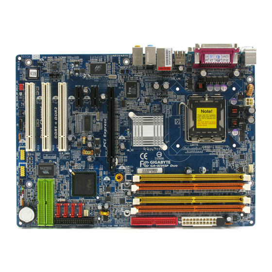
Page 6: Ga-8I915P Duo (Pro) Motherboard Layout
GA-8I915P Duo (Pro) Motherboard Layout KB_MS ATX_12V SPDIF_O SPDIF_I AUDIO1 Broadcom AUDIO2 5751 /5789 CD_IN AZALIA_FP Broadcom 5751/5789 CODEC Only for GA-8I915P Duo Pro. Only for GA-8I915P Duo. PWR_FAN LGA775 Intel 915P NB_FAN PCIE_16 Main PCIE_1 BIOS Backup PCIE_2 BIOS... -
Page 7: Block Diagram
3 PCI PCICLK (33MHz) (Note) To use a DDRII 600 memory module on the motherboard, you must install an 800MHz FSB processor and overclock in BIOS. Only for GA-8I915P Duo Pro. Only for GA-8I915P Duo. LGA775 Processor Host Interface Intel... - Page 8 - 8 -...
-
Page 9: Chapter 1 Hardware Installation
2. Damage as a result of violating the conditions recommended in the user manual. 3. Damage due to improper installation. 4. Damage due to use of uncertified components. 5. Damage due to use exceeding the permitted parameters. 6. Product determined to be an unofficial Gigabyte product. - 9 - Hardware Installation... -
Page 10: Feature Summary
2 RJ 45 port--LAN1 / LAN2 (Note) To use a DDRII 600 memory module on the motherboard, you must install an 800MHz FSB processor and overclock in BIOS. Only for GA-8I915P Duo Pro. Only for GA-8I915P Duo. GA-8I915P Duo (Pro) Motherboard... - Page 11 Use of licensed AWARD BIOS Supports Dual BIOS /Q-Flash/Multilanguage Additional Features Supports @BIOS Supports EasyTune Overclocking Over Voltage via BIOS (CPU/DDR/PCI-E) Over Clock via BIOS (CPU/DDR) Form Factor ATX form factor; 30.5cm x 24.4cm Only for GA-8I915P Duo Pro. - 11 - Hardware Installation...
-
Page 12: Installation Of The Cpu And Heatsink
Avoid twisting or bending motions that might cause damage to the CPU during installation.) GA-8I915P Duo (Pro) Motherboard Fig. 2 Remove the plastic covering on the CPU socket. -
Page 13: Installation Of The Heatsink
1-3-2 Installation of the Heatsink Fig.1 Please apply an even layer of heatsink paste on the surface of the installed CPU. Fig. 3 Place the heatsink atop the CPU and make sure the push pins aim to the pin hole on the motherboard.Pressing down the push pins diagonally. -
Page 14: Installation Of Memory
The motherboard supports DDR II & DDR memory modules, whereby BIOS will automatically detect memory capacity and specifications. Memory modules are designed so that they can be inserted only in one direction. The memory capacity used can differ with each slot. GA-8I915P Duo (Pro) Motherboard Notch DDR II Fig.1... - Page 15 GA-8I915P Duo (Pro) supports the Dual Channel Technology. After operating the Dual Channel Technology, the bandwidth of Memory Bus will add double up to 6.4GB/s(DDR) ; 8.5GB(DDRII) GA-8I915P Duo (Pro) includes 4 DIMM sockets, and each Channel has two DIMM sockets as following: Channel A : DDR 1...
-
Page 16: Installation Of Expansion Cards
Power on the computer, if necessary, setup BIOS utility of expansion card from BIOS. Install related driver from the operating system. Installing a PCI Express x 16 expansion card: GA-8I915P Duo (Pro) Motherboard Please carefully pull out the small white- drawable bar at the end of the PCI Express x 16 slot when you try to install/Uninstall the VGA card. -
Page 17: I/O Back Panel Introduction
Devices like CD-ROM, walkman etc. can be connected to Line In jack. Line Out (Front Speaker Out) Connect the stereo speakers, earphone or front surround channels to this connector. MIC In Microphone can be connected to MIC In jack. Only for GA-8I915P Duo Pro. - 17 - Hardware Installation... -
Page 18: Connectors Introduction
ATX_12V ATX (Power Connector) CPU_FAN SYS_FAN PWR_FAN NB_FAN IDE1 IDE2/IDE3 S_ATA0 / S_ATA1 / S_ATA2 / S_ATA3 Only for GA-8I915P Duo Pro. GA-8I915P Duo (Pro) Motherboard PWR_LED F_PANEL AZALIA_FP CD_IN F_USB1 / F_USB2 F1_1394 / F2_1394 CLR_CMOS - 18 -... - Page 19 1/2) ATX_12V/ATX (Power Connector) With the use of the power connector, the power supply can supply enough stable power to all the components on the motherboard. Before connecting the power connector, please make sure that all components and devices are properly installed. Align the power connector with its proper location on the motherboard and connect tightly.
- Page 20 Please remember to connect the power to the CPU fan to prevent CPU overheating and failure. 6) NB_FAN (Chip Fan Connector) If you installed wrong direction, the chip fan will not work. Sometimes will damage the chip fan. (Usually black cable is GND) GA-8I915P Duo (Pro) Motherboard CPU_FAN Pin No. Definition...
- Page 21 7) FDD (Floppy Connector) The FDD connector is used to connect the FDD cable while the other end of the cable connects to the FDD drive. The types of FDD drives supported are: 360KB, 720KB, 1.2MB, 1.44MB and 2.88MB. Please connect the red power connector wire to the pin1 position. 8/9) IDE1/IDE2/IDE3 (IDE Connector) An IDE device connects to the computer via an IDE connector.
- Page 22 11) PWR_LED PWR_LED is connect with the system power indicator to indicate whether the system is on/off. It will blink when the system enters suspend mode. GA-8I915P Duo (Pro) Motherboard Pin No. Definition Pin No.
-
Page 23: F_Panel (Front Panel Jumper)
12) F_PANEL (Front Panel Jumper) Please connect the power LED, PC peaker, reset switch and power switch etc of your chassis front panel to the F_PANEL connector according to the pin assignment below. HD (IDE Hard Disk Active LED) (Blue) SPEAK (Speaker Connector) (Amber) RES (Reset Switch) - Page 24 HD Audio is the default setting for this connector. To enable AC'97 Audio, from BIOS settings, set Front Panel Type under Integrated Peripherals to AC97. 14) CD_IN (CD IN) Connect CD-ROM or DVD-ROM audio out to the connector. GA-8I915P Duo (Pro) Motherboard HD Audio: AC'97 Audio: Pin No.
- Page 25 IEEE1394 cable, incorrect connection between the cable and connector will make the device unable to work or even damage it. For optional IEEE1394 cable, please contact your local dealer. Only for GA-8I915P Duo Pro. Pin No. Definition Power...
-
Page 26: Clear Cmos
18) CLR_CMOS (Clear CMOS) You may clear the CMOS data to its default values by this jumper. To clear CMOS, temporarily short 1-2 pin. Default doesn't include the "Shunter" to prevent from improper use this jumper. GA-8I915P Duo (Pro) Motherboard Pin No. Definition... - Page 27 19) BAT(Battery) Danger of explosion if battery is incorrectly replaced. Replace only with the same or equivalent type recommended by the manufacturer. Dispose of used batteries according to the manufacturer's instructions. If you want to erase CMOS... 1.Turn OFF the computer and unplug the power cord. 2.Remove the battery, wait for 30 second.
- Page 28 GA-8I915P Duo (Pro) Motherboard - 28 -...
-
Page 29: Chapter 2 Bios Setup
BIOS needs to be reset to its original settings. If you wish to upgrade to a new BIOS, either Gigabyte's Q-Flash or @BIOS utility can be used. Q-Flash allows the user to quickly and easily update or backup BIOS without entering the operating system. -
Page 30: The Main Menu (For Example: Bios Ver. : F5)
This setup page is select multi language. Load Fail-Safe Defaults Fail-Safe Defaults indicates the value of the system parameters which the system would be in safe configuration. Only for GA-8I915P Duo Pro. GA-8I915P Duo (Pro) Motherboard Select Language 1 Load Fail-Safe Defaults... - Page 31 Load Optimized Defaults Optimized Defaults indicates the value of the system parameters which the system would be in best performance configuration. Set Supervisor Password Change, set, or disable password. It allows you to limit access to the system and Setup, or just to Setup. Set User Password Change, set, or disable password.
-
Page 32: Standard Cmos Features
Write precomp Landing Zone Landing zone Sector Number of sectors If a hard disk has not been installed, select NONE and press <Enter>. Only for GA-8I915P Duo Pro. GA-8I915P Duo (Pro) Motherboard Standard CMOS Features Thu, Apr 29 2004 22:31:24... -
Page 33: Extended Memory
Drive A / Drive B The category identifies the types of floppy disk drive A or drive B that has been installed in the computer. None No floppy drive installed 360K, 5.25" 5.25 inch PC-type standard drive; 360K byte capacity. 1.2M, 5.25"... -
Page 34: Advanced Bios Features
Select your boot device priority by USB-HDD. Select your boot device priority by LAN. Disabled Select your boot device priority by Disabled. Only for GA-8I915P Duo Pro. (Note) This item will show up when you install a processor which supports this function. GA-8I915P Duo (Pro) Motherboard... - Page 35 Password Check Setup The system will boot but will not access to Setup page if the correct password is not entered at the prompt. (Default value) System The system will not boot and will not access to Setup page if the correct password is not entered at the prompt.
-
Page 36: Integrated Peripherals
RAID Select onboard Seria ATA function as RAID. (Default value) AHCI Support hotplug function under OS. WinXP,2000 only. Disabled Select onboard Seria ATA function as ATA. Only for GA-8I915P Duo Pro. GA-8I915P Duo (Pro) Motherboard Integrated Peripherals [Enabled] [RAID] Auto Ch.0 Master/Slave... - Page 37 AC97 Audio Panel to the AZALIA_FP connector, set this item to AC97. AC97 Set front audio panel type to AC97. HD Audio Set front audio panel type to HD Audio. (Default value) Only for GA-8I915P Duo Pro. - 37 - BIOS Setup...
- Page 38 This item allows you to determine which Infra Red(IR) function of Onboard I/O chip. ASKIR Set onboard I/O chip UART to ASKIR Mode. IrDA Set onboard I/O chip UART to IrDA Mode. (Default value) Only for GA-8I915P Duo Pro. GA-8I915P Duo (Pro) Motherboard - 38 -...
- Page 39 UR2 Duplex Mode This feature allows you to seclect IR mode. This function will available when "UART Mode Select" doesn't set at Normal. Half IR Function Duplex Half. (Default value) Full IR Function Duplex Full. Onboard Parallel port Disabled Disable onboard LPT port. 378/IRQ7 Enable onboard LPT port and address is 378/IRQ7.
-
Page 40: Power Management Setup
Time (hh: mm: ss) Alarm : Power On By Mouse Disabled Disable this function. (Default value) Double Click Double click on PS/2 mouse left button to power on the system. Only for GA-8I915P Duo Pro. GA-8I915P Duo (Pro) Motherboard Power Management Setup [S1(POS)] [Instant-off] [Enabled]... - Page 41 Power On By Keyboard Password Enter from 1 to 5 characters to set the Keyboard Power On Password. Disabled Disabled this function. (Default value) Keyboard 98 If your keyboard have "POWER Key" button, you can press the key to power on the system. KB Power ON Password When "Power On by Keyboard"...
-
Page 42: Pnp/Pci Configurations
PCI 1 IRQ Assignment Auto 3,4,5,7,9,10,11,12,14,15 PCI 2 IRQ Assignment Auto 3,4,5,7,9,10,11,12,14,15 PCI 3 IRQ Assignment Auto 3,4,5,7,9,10,11,12,14,15 Only for GA-8I915P Duo Pro. GA-8I915P Duo (Pro) Motherboard PnP/PCI Configurations [Auto] [Auto] [Auto] +/-/PU/PD: Value F10: Save ESC: Exit F6: Fail-Safe Default F7: Optimized Defaults Auto assign IRQ to PCI 1. -
Page 43: Pc Health Status
The speed of CPU fan will increase linearly depand on the temperature if the temperature is more than 41 degree and less than 65 degree. When the CPU temperature is lower than 40 degrees Celsius, CPU fan will be disable. Only for GA-8I915P Duo Pro. PC Health Status 4687 RPM [Disabled]... -
Page 44: Mb Intelligent Tweaker(M.i.t.)
CPU computing power to maximize system performance. Disabled Disable this function. (Default value) Cruise Set C.I.A.2 to Cruise. (Automatically increase CPU frequency(5%,7%) by CPU loading. Only for GA-8I915P Duo Pro. GA-8I915P Duo (Pro) Motherboard MB Intelligent Tweaker(M.I.T.) [15X] [Auto] [Disabled]... - Page 45 Sports Set C.I.A.2 to Sports. (Automatically increase CPU frequency(7%,9%) by CPU loading. Racing Set C.I.A.2 to Racing. (Automatically increase CPU frequency(9%,11%) by CPU loading. Turbo Set C.I.A.2 to Turbo. (Automatically increase CPU frequency(15%,17%) by CPU loading. Full Thrust Set C.I.A.2 to Full Thrust. (Automatically increase CPU frequency(17%,19%) by CPU loading.
-
Page 46: Select Language
ESC: Quit F8: Dual BIOS 1/Q-Flash Fail-Safe defaults contain the most appropriate values of the system parameters that allow minimum system performance. Only for GA-8I915P Duo Pro. GA-8I915P Duo (Pro) Motherboard Select Language 1 Load Fail-Safe Defaults Load Optimized Defaults... -
Page 47: Load Optimized Defaults
Setup Menu. If you select "Setup" at "Password Check" in Advance BIOS Features Menu, you will be prompted only when you try to enter Setup. Only for GA-8I915P Duo Pro. Select Language 1 Load Fail-Safe Defaults... -
Page 48: Save & Exit Setup
ESC: Quit F8: Dual BIOS 1/Q-Flash Type "Y" will quit the Setup Utility without saving to RTC CMOS. Type "N" will return to Setup Utility. Only for GA-8I915P Duo Pro. GA-8I915P Duo (Pro) Motherboard Select Language 1 Load Fail-Safe Defaults... -
Page 49: Chapter 3 Install Drivers
Chapter 3 Install Drivers Pictures below are shown in Windows XP. Insert the driver CD-title that came with your motherboard into your CD-ROM drive, the driver CD-title will auto start and show the installation guide. If not, please double click the CD-ROM device icon in "My computer", and execute the Run.exe. -
Page 50: Software Applications
Software Applications This page displays all the tools that Gigabyte developed and some free software, you can choose anyone you want and press "install" to install them. Driver CD Information This page lists the contents of software and drivers in this CD-title. -
Page 51: Hardware Information
Hardware Information This page lists all device you have for this motherboard. Contact Us Please see the last page for details. - 51 - Install Drivers... - Page 52 GA-8I915P Duo (Pro) Motherboard - 52 -...
-
Page 53: Chapter 4 Appendix
Motherboard Intelligent Tweaker (M.I.T.) allows user to access and change BIOS feature settings with relative speed and ease. Through GIGABYTE M.I.T. feature the user is no longer required to switch into different modes within BIOS setup in order to change system settings such as the CPU system bus, memory timings or to enabled Gigabyte's unique C.I.A. -
Page 54: Xpress Recovery Introduction
Once you have completed this step, subsequent access to Xpress Recovery can also function by pressing the F9 key during computer power on. Verifying DMI Pool Data Boot from CD: Xpress Recovery V1.0 (C) Copy Right 2003. GIGABYTE Technology CO. , Ltd. 1. Execute Backup Utility 2. Execute Restore Utility 3. Remove Backup Image 4. - Page 55 Press DEL to enter SETUP / Q-Flash, F9 For Xpress Recovery 08/16/2002-I845GE-6A69YG01C-00 Xpress Recovery V1.0 (C) Copy Right 2003. GIGABYTE Technology CO. , Ltd. If you have already entered Xpress Recovery by booting from the CD-ROM, you can enter Xpress Recovery in the future by pressing the F9 key.
- Page 56 If you wish to remove the need for password entry, please select "Set Password" and under "New Password/Confirm Password", make sure there is no entry and then press "Enter" to remove password requirement. 5. Exit and Restart: Exit and restart your computer. GA-8I915P Duo (Pro) Motherboard - 56 -...
-
Page 57: Flash Bios Method Introduction
Wide Range Protection Auto Recovery Halt On Error Keep DMI Data Copy Main ROM Data to Backup PgDn/PgUp: Modify Only for GA-8I915P Duo Pro. Load Fail-Safe Defaults Load Optimized Defaults Set Supervisor Password Set User Password Save & Exit Setup... - Page 58 The means that the Backup BIOS works normally and could automatically recover the Main BIOS. (This auto recovery utility is set by system automatically and can’ t be changed by user.) Load Default Settings Load dual BIOS default value. Save Settings to CMOS Save revised setting. GA-8I915P Duo (Pro) Motherboard - 58 -...
-
Page 59: Q-Flash Utility
Updating BIOS with Q-Flash Utility on Dual BIOS Motherboards. Some of Gigabyte motherboards are equipped with dual BIOS. In the BIOS menu of the motherboards supporting Q-Flash and Dual BIOS, the Q-Flash utility and Dual BIOS utility are combined in the same screen. - Page 60 Action bar: Contains the names of four actions needed to operate the Q-Flash/Dual BIOS utility. Pressing the buttons mentioned on your keyboards to perform these actions. GA-8I915P Duo (Pro) Motherboard Select Language Load Fail-Safe Defaults Load Optimized Defaults...
- Page 61 Using the Q-Flash utility: This section tells you how to update BIOS using the Q-Flash utility. As described in the "Before you begin" section above, you must prepare a floppy disk having the BIOS file for your motherboard and insert it to your computer.
- Page 62 Secondary Master : CREATIVEDVD-RM DVD1242E BC101 Secondary Slave : None Press DEL to enter SETUP / Dual BIOS / Q-Flash / F9 For Xpress Recovery 09/23/2003-i875P-6A79BG03C-00 GA-8I915P Duo (Pro) Motherboard Dual BIOS Utility Main Bios Disable Boot From Main Bios...
-
Page 63: Updating Bios With Q-Flash Utility On Single-Bios Motherboards
Press Y on your keyboard to save and exit. Part Two: Updating BIOS with Q-Flash Utility on Single-BIOS Motherboards. This part guides users of single-BIOS motherboards how to update BIOS using the Q-Flash CMOS Setup Utility-Copyright (C) 1984-2004 Award Software Standard CMOS Features Advanced BIOS Features... - Page 64 After BIOS file is read, you'll see a confirmation dialog box asking you "Are you sure to update BIOS?" Please do not take out the floppy disk when it begins flashing BIOS. GA-8I915P Duo (Pro) Motherboard Q-Flash Utility V1.30 Keep DMI Data...
- Page 65 Press Y button on your keyboard after you are sure to update BIOS. Then it will begin to update BIOS. The progress of updating BIOS will be shown at the same time. Flash Type/Size...SST 49LF002A >>>>>>>>>>>>>>>>>>>... Enter : Run Don't Turn Off Power or Reset System Press any keys to return to the Q-Flash menu when the BIOS updating procedure is completed.
-
Page 66: @Bios Utility
Please search for BIOS unzip file, downloading from internet or any other methods (such as: 8I915P Duo Pro.F1). Complete update process following the instruction. GA-8I915P Duo (Pro) Motherboard Utility Fig 2. Installation Complete and Run @BIOS Click Sart/ Programs/ GIGABYTE/@BIOS Fig 4. - Page 67 III. In method I, if the BIOS file you need cannot be found in @BIOSTM server, please go onto Gigabyte's web site for downloading and updating it according to method II. IV. Please note that any interruption during updating will cause system unbooted...
-
Page 68: Serial Ata Bios Setting Utility Introduction
Due to the fault tolerance, if any RAID 1 drive fails, data access will not be affected as long as there are other working drives in the array. Only for GA-8I915P Duo Pro. GA-8I915P Duo (Pro) Motherboard ICH6R chipset supports are RAID 0 and ®... - Page 69 Please follow the steps below to construct a complete RAID array: 1) Have ready your hard drives for RAID construction. Note: To achieve best performance, it is recommended that the hard drives used are of similar make and storage capacity. 2) Please attach the hard drive connectors to their appropriate location on the motherboard ie.
-
Page 70: Create Raid Volume
[hi]-Change [TAB]-Next There are two RAID levels: RAID0(Stripe) and RAID1(Mirror). After selecting the RAID level, press Enter to select Strip Size. GA-8I915P Duo (Pro) Motherboard [ CREATE VOLUME MENU ] Name : RAID_Volume0 RAID0(Stripe) - Page 71 The KB is a unit of Strip Size. You can set disk block size with this item. The disk block size can be set from 4KB to 128KB. After you set disk block size, press Enter to set disk Capacity. Intel(R) Application Accelerator RAID Option ROM v4.0.6180 Copyright(C) 2003-04 Intel Corporation.
- Page 72 WARNING : ALL DATA ON SELECTED DISKS WILL BE LOST. Are you sure you want to creat this volume? (Y/N) : Press "ENTER" to Create the specified volume [hi]-Change [TAB]-Next GA-8I915P Duo (Pro) Motherboard [ CREATE VOLUME MENU ] Name : RAID_Volume0 RAID0(Stripe)
-
Page 73: Delete Raid Volume
After the completion, you will see the detailed information about the RAID, such as RAID level, disk block size, disk name and disk capacity, etc. Intel(R) Application Accelerator RAID Option ROM v4.0.6180 Copyright(C) 2003-04 Intel Corporation. All Rights Reversed. RAID Volumes : Name RAID_Volume0 Physical Disks :... - Page 74 (Each time you add a new hard drive to a RAID array, the RAID driver will have to be installed under Windows once for that hard drive. After that, the driver will not have to be installed.) Note: In the menu list, Intel Application Accelerator 4.0 is Intel ICH6R chipset. GA-8I915P Duo (Pro) Motherboard - 74 -...
-
Page 75: / 5.1 / 7.1 Channel Audio Function Introduction
4-1-4 2 / 4 / 5.1 / 7.1 Channel Audio Function Introduction After installation of the audio driver, you'll find an icon in the system area. Double click the icon to se- lect the function. If the icon can not be found, go to the control panel from the system menu and double click the C-Media CPL icon. - Page 76 The function to manually modify speaker settings. GA-8I915P Duo (Pro) Motherboard The function to adjust speaker volume. - 76 - Line Out...
- Page 77 4 Channel Audio Setup STEP 1 : Connect the front speaker to "Front Speaker Out" and the surround speaker to "Surround speaker out". STEP 2: After installation of the audio driver, you'll find an icon in the system area. Double click the icon to select the function.
- Page 78 The function to manually modify speaker setting. GA-8I915P Duo (Pro) Motherboard The function to adjust speaker volume. - 78 - Front Speaker Out...
- Page 79 7.1 Channel Audio Setup STEP 1 : Connect the front speaker to "Front Speaker Out", the surround speaker to "Surround speaker out", and the center/subwoofer speaker to "Center/Subwoofer Speaker Out", and the back surround speaker to "Back surround speaker out". STEP 2: After installation of the audio driver, you find an icon in the system area.
- Page 80 "C-Media Azalia Front Panel" option will show up for you to use the multiple audio output function. Note:The function can be used only when you con- nect the audio device to front panel. GA-8I915P Duo (Pro) Motherboard - 80 -...
-
Page 81: Troubleshooting
Question 6: How do I disable onboard VGA card in order to add an external VGA card? Answer: Gigabyte motherboards will auto-detect the external VGA card after it is plugged in, so you don't need to change any setting manually to disable the onboard VGA. - Page 82 8 beeps Display memory read/write failure 9 beeps ROM checksum error 10 beeps CMOS shutdown register read/write error 11 beeps Cache memory bad GA-8I915P Duo (Pro) Motherboard g AWARD BIOS Beep Codes 1 short: System boots successfully 2 short: CMOS setting error...
- Page 83 - 83 - Appendix...
- Page 84 GA-8I915P Duo (Pro) Motherboard - 84 -...
- Page 85 - 85 - Appendix...
- Page 86 GA-8I915P Duo (Pro) Motherboard - 86 -...
- Page 87 TEL: +886 (2) 8912-4888 FAX: +886 (2) 8912-4003 Tech. Support : http://tw.giga-byte.com/TechSupport/ServiceCenter.htm Non-Tech. Support(Sales/Marketing) : http://ggts.gigabyte.com.tw/nontech.asp WEB address (English): http://www.gigabyte.com.tw WEB address (Chinese): http://chinese.giga-byte.com — U.S.A. G.B.T. INC. Address: 17358 Railroad St, City of Industry, CA 91748. TEL: +1 (626) 854-9338 FAX: +1 (626) 854-9339 Tech.
- Page 88 Chengdu TEL: +86-028-85236930 FAX: +86-028-85256822 Xian TEL: +86-029-85531943 FAX: +86-029-85539821 Shenyang TEL: +86-024-23960918 FAX: +86-024-23960918-809 GA-8I915P Duo (Pro) Motherboard — Australia GIGABYTE TECHNOLOGY PTY. LTD. Tech. Support : http://www.giga-byte.com.au/TechSupport/ServiceCenter.htm Non-Tech. Support(Sales/Marketing) : http://ggts.gigabyte.com.tw/nontech.asp WEB address : http://www.giga-byte.com.au — France GIGABYTE TECHNOLOGY FRANCES S.A.R.L.