Table of Contents
Advertisement
Service
Manual
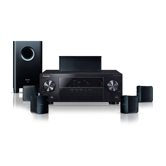
POWERED SUBWOOFER
HTP105/205-SW
PIONEER CORPORATION
PIONEER ELECTRONICS SERVICE, INC.
©
PIONEER CORPORATION 1999
CONTENTS
1. SAFETY INFORMATION ............................................. 2
2. DISASSEMBLY ............................................................ 3
5. PCB PARTS LIST ........................................................ 8
6. PANEL FACILITIES ...................................................... 9
7. SPECIFICATIONS ....................................................... 10
4-1, Meguro 1-Chome, Meguro-ku, Tokyo 153-8655, Japan
P.O.Box 1760, Long Beach, CA 90801-1760, U.S.A.
HTP105/205-SW
ORDER NO.
PET99019
1
Advertisement
Table of Contents

Related Manuals for Pioneer HTP-105


Summary of Contents for Pioneer HTP-105
-
Page 1: Table Of Contents
4. SCHEMATIC AND PCB CONNECTION DIAGRAMS .. 6 5. PCB PARTS LIST ............8 6. PANEL FACILITIES ............9 7. SPECIFICATIONS ............10 PIONEER CORPORATION 4-1, Meguro 1-Chome, Meguro-ku, Tokyo 153-8655, Japan PIONEER ELECTRONICS SERVICE, INC. P.O.Box 1760, Long Beach, CA 90801-1760, U.S.A. © PIONEER CORPORATION 1999... -
Page 2: Safety Information
PIONEER Earth (Using AC adapter ground Service Manual. A subscription to, or additional copies plug as required) of, PIONEER Service Manual may be obtained at a AC Leakage Test nominal charge from PIONEER. -
Page 3: Disassembly
HTP105/205-SW 2. DISASSEMBLY POWER AMP SECTION GRILLE SECTION • Remove the 8 screws from the power amplifier. • The grill is attached to the cabinet by its bosses applied • Remove the connector lead, etc. with adhesive. To detach it, pry it open by inserting a flat blade scewdriver between the cabinet and the grille. -
Page 4: Exterior Section
HTP105/205-SW 3.2 EXTERIOR SECTION Parts List Mark No. Description Parts No. Cabinet Enclosure 264388 Amplifier Assembly 264462 Grille Assembly 264353 Paper Port Tube 256946 Front Port Ring 254306 Rear Port Ring 254346 Label FTC Sticker 268182 UL-CUL Label 268197 Transducer 264719 Screw (for Amplifier and Trans) 221904... - Page 5 http://getMANUAL.com HTP105/205-SW 3.3 POWER AMP SECTION Parts List Mark No. Description Parts No. Mark No. Description Parts No. Panel Rear Assy 046981 2P Cord 044899 Power Amp PCB Section 047259 AC Cord 046947 Screw (3X10 BL) 075640 BRKT PCB C 077876 Screw (4X10 BL) 075659...
-
Page 6: Schematic And Pcb Connection Diagrams
HTP105/205-SW 4. SCHEMATIC AND PCB CONNTCTION DIAGRAMS NOTE FOR PCB DIAGRAMS NOTE FOR SCHEMATIC DIAGRAMS (Type 1A) 1. When ordering service parts, be sure to refer to 1. Partnumbers in PCB diagrams match those in the schematic diagrams. "PARTS LIST of EXPLODED VIEWS" or "PCB 2. - Page 7 HTP105/205-SW 4.1 CIRCUIT DIAGRAM...
-
Page 8: Pcb Parts List
HTP105/205-SW 5. PCB PARTS LIST NOTES: Parts marked by "NSP" are generally unavailable because they are not in our Master Spare Parts List. mark found on some component parts indicates the importance of the safety factor of the part. Therefore, when replacing, be sure to use parts of identical designation. -
Page 9: Panel Facilities
HTP105/205-SW 6. PANEL FACILITIES REAR SECTION 1 POWER indicator Illuminates RED when the power is being supplied. 2 Subwoofer LEVEL knob LINE LEVEL LEVEL Volume of subwoofer is adjusted with this knob. Turn this INPUT knob clockwise to raise the level. POWER ÷... -
Page 10: Specifications
HTP105/205-SW A floor, bass-reflext type, with a built-in amplifier having a PVC-sheet finishint with a wood pattern. 7. SPECIFICATIONS HTP105/205-SW Cabinet A floor, bass-reflext type, with a built-in amplifier having a PVC-sheet finishint with a wood pattern. Speaker 20 cm (8 inch) Continuous Average Power Output is 50 Watts* min, at 4 ohms from 30 Hertz to 200 Hertz with Power Amplifier no more than 1% total harmonic distortion. - Page 11 HTP105/205-SW NOTES...
- Page 12 HTP105/205-SW...