
Related Manuals for Vaillant ecoMAX pro 18E


Summary of Contents for Vaillant ecoMAX pro 18E
- Page 1 To be left with the user Instructions for Use, Installation and Servicing ecoMAX pro Wall hung condensing 18 E boilers for traditional open vented 28 E systems...
-
Page 2: Table Of Contents
Table of Contents ..........Page . -
Page 3: Contents Included With Ecomax Pro Boiler
List of Content 1 Introduction 2 1.1 Contents included with ecoMAX pro boiler Vaillant Ltd. support the Benchmark initiative. At the rear of this literature you will find a Ensure that all contents are included before commencing Benchmark gas boiler commissioning checklist. It is very important that this is completed correctly at the installation. -
Page 4: General Information
2.1 General Information 2. Directive 73/23/EEC on the harmonisation of the Laws Thank you for choosing a Vaillant boiler. The information of the Member States relating to electrical equipment given in this booklet will enable you to obtain the best designed for use within certain voltage limits. -
Page 5: Protection Against Freezing
Contact your installation/ servicing company if the fault persists. 2.17 Guarantee Vaillant provide a full parts and labour warranty for your 2.11 Boilers Installed in a Compartment or Cupboard appliance. If the boiler is fitted into a compartment or cupboard it The appliance must be installed by a suitably competent does not require ventilation openings. -
Page 6: Operating The Boiler
3 Operating the boiler 3.1 Sealed Central Heating Systems only 3.4 To Turn the Boiler Off CAUTION: A sealed water system must be filled and Normally the boiler will be turned off by the heating pressurised by a competent person. system controls. -
Page 7: General Information 4
The ecoMAX pro 28E, only, can be field adjusted for use without permission, in writing, from Vaillant. on LPG (propane G31). Any alteration that is not approved by Vaillant, could Where no British Standards exists, materials and invalidate the warranty and could also infringe the equipment should be fit for their purpose and of suitable current issue of the Statutory Requirements. -
Page 8: Boiler Specification
4 General information Boiler specification ecoMAX pro ecoMAX pro 18 E 28 E Units Maximum CH heat input (net) 18.9 28.6 CH heat output (80/60 °C) 5.0 - 18.3 5.3 - 28.2 CH heat output (50/30 °C) 5.3 - 20.0 5.7 - 30.6 SEDBUK Band SAP Seasonal Efficiency... -
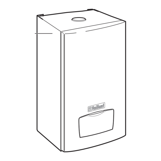
Page 9: Dimensions And Data Labels
General information 4 Fig 4.1 Fig 4.2 Instructions for Use, Installation and Servicing ecoMAX pro... -
Page 10: Electrical Supply
4 General information 4.5 Electrical Supply The boiler must be earthed. All system components shall be of an approved type and all wiring to current I.E.E. wiring regulations. External wiring must be correctly earthed, polarised and in accordance with the relevant standards. In GB this is BS 7671. -
Page 11: Boiler Location And Ventilation 5
Institute of Gas Engineers document IGE/UP/7/1998. If in doubt seek advice from the local gas undertaking or Vaillant. 5.4 Room Ventilation The boiler is room sealed, so when it is installed in a room or space, a permanent air vent is not required. -
Page 12: Water System
6 Water system 6.1 Draining Tap A draining tap must be provided at all the lowest points TABLE 2 of the system, which will allow the entire system and hot Model Minimum flow rate water system to be drained. Draining taps shall be to the current issue of BS 2879. ecoMAX pro 18 E 773.8 litres/hr ecoMAX pro 28 E... -
Page 13: Inhibitor
Vaillant VANTAGE unvented cylinders and adding inhibitor. Take care to ensure that all low points in MUST not be used in connection with these the system are fully drained. -
Page 14: Safety Valve
6 Water system 6.9.1 Safety Valve 6.9.3 Pressure Gauge A safety valve must be fitted to a sealed system. A pressure gauge with a set pointer and covering at least It shall be preset, non-adjustable with a lift pressure of 0 to 4 bar (0 to 60 lb/in2) shall be fitted permanently to 3-bar, incorporating seating of a resilient material, a test the system in a position where it can be seen when... -
Page 15: Flue 7
In certain weather conditions a plume of water vapour result in damage and injury. You will find a list may be visible from the flue terminal. Positions where of genuine flue pipes in the Vaillant installation this could be a nuisance should be avoided. manual for flue pipes. - Page 16 7 Flue 1) In addition, the terminal should not be nearer TERMINAL POSITION than 150mm to an opening in the building fabric A 1) Directly below an opening, above an opening formed for the purpose of accommodating a built-in element such as a window. or horizontal to an opening i.e.
-
Page 17: Installation Preparation 8
Installation preparation 8 Boiler fixing 9 Boiler fixing 8.1 Unpacking of Boiler Stand the boiler carton upright. 9.1 Fitting the boiler hanging bracket Cut and remove the securing straps and lift off the carton If previously removed, reposition the wall template over sleeve. -
Page 18: Gas, Water And Condensate Connections
10 Gas, Water and Condensate connections 10.1 Gas Connection Before connection check the supply of local gas. The gas supply can be connected from below, or through the wall at the rear of the boiler. See fig 10.1. and refer to section 4.3. -
Page 19: Electrical Connections 11
This appliance must be wired in accordance with these instructions. Any fault arising from incorrect wiring cannot be put right under the terms of the Vaillant guarantee. 11.1 Appliance, pump and external controls. ecoMAX pro boilers are fitted with a terminal box located at the base of the boiler into which all connections are made. -
Page 20: Commissioning
12 Commissioning Please ensure the “Benchmark” service record is Caution! completed and left with the user. Before operating the boiler check the data badge and ensure that the correct gas type Note! appliance has been installed. During commissioning the overheat thermostat may trip before air is completely removed from the system. -
Page 21: Initial Lighting
Commissioning 12 12.4 Initial Lighting 12.5 Testing - Gas The lighting procedure of the boiler is fully automated. The boiler is supplied ready adjusted and no further gas To prepare the boiler for initial lighting first ensure that all adjustments are necessary, however both the gas inlet external controls are not calling for heat. -
Page 22: User Controls And Options
12 Commissioning 12.7 User Controls and Options The mains/reset switch is used to restart the boiler after a fault condition has occurred, i.e. ignition failure. The user display (see section 3.3) allows the user to set the desired central heating temperature. 12.8 Temperature Display The boiler shows the operating temperature of the unit. -
Page 23: Natural Gas To Lpg Conversion (Ecomax Pro 28E Only)
Conversion 13 Natural Gas to LPG conversion (ecoMAX pro 28E - Press the ‘-‘ key and scroll through until ‘96’ (installer only) mode) is shown on the screen, then press the ‘mode’button again. The ecoMAX pro 28E is able to be field adjusted for use on LPG –... - Page 24 13 Conversion Appliance CO 2 content at nominal "A" throttle – load for LPG in vol. % "Pmax" rotate to increase ecoMAX pro 28E 10.5 % ± 0.2 % "B" offset adjustment "Pmin" rotate to increase Fig 13.4 - Again in screen ‘8’, Set the appliance fan speed/burner to minimum by pressing the ‘-‘...
-
Page 25: Servicing 14
Vaillant establish the combustion performance of the appliance. Any spare parts which might be required boiler. - Page 26 14 Servicing Overview of the inspection and maintenance tasks Activity Column Column 2 Check the air/ gas flue system and ensure it is not blocked, damaged and is fitted correctly. Measure the gas rate during operation (see table 5.1. inside section 5 commissioning part I). If the gas rate is lower than the minimum gas rate, follow the maintenance schedule in column 2.
- Page 27 Servicing 14 All routine servicing requirements can be achieved by the Should the flame show signs of lift, sooting or appear removal of the front panel, inner panel and chassis front yellow then it will be necessary to service the burner, only.
-
Page 28: Spark Electrode
14 Servicing 14.4 Spark Electrode Remove and discard the burner door seal and replace Disconnect the ignition lead and earth lead from the with new, see fig 14.7. igniter unit and two securing screws at the spark Removal of the burner is not necessary during a normal electrode. -
Page 29: Condensate Trap And Siphonic Drain
Servicing 14 14. 7 Condensate Trap and Syphonic Drain. The condense drain does not normally need removing during servicing. To flush the condense drain carefully pour water into the heat exchanger and check that water flows freely to drain. Refer to fig 14.10. If the condense drain is blocked. Remove the clips securing the flexible tubes to the adapter by twisting the clips slightly to disengage the clip jaws SECTION THROUGH... -
Page 30: Inner Casing Panel Seal Check
14 Servicing 14.8 Inner casing panel seal check • Check the air/flue gas system for leaks, check its Refer to fig 14.11. fastening Check the condition of the seal, replace as required. • Check for ignition and an even flame on the burner. To replace remove the old seal, thoroughly clean the •... -
Page 31: Combustion Analysis 15
Combustion analysis 15 Note! Press the ‘+‘ key and scroll through until ‘8’ is shown on The boiler is fitted with a combustion analysis the left of the screen, then press the ‘mode’ button again. test point. A suitable combustion analyser can be connected to this point to establish the combustion performance of the boiler. -
Page 32: Fault Finding
• A series of screens are then available for service may be necessary to repeat steps 3,4 and 5 to functions. An example is shown in fig 16.2 (screen 23 adjust the appliance fan speed/burner. ‘product code’ for the ecoMAX pro 18E). TESTING GAS Case Off Case On Burner CO2 (G20) 9.1+0.2-0.5... - Page 33 Fault finding 16 Description Comments Action Central heating maximum output Set minimum to maximum product output (kW) adjustable Flue system pressure loss No function adjustable Minimum temperature for Set minimum temperature adjustable Central Heating (22°, 28°, 38° or 50°C) Maximum temperature for Set maximum temperature adjustable Central Heating...
-
Page 34: Fault Memory
16 Fault finding 16.2 Fault Memory The fault memory stores details of the five most recent faults. To display the fault memory, proceed as follows; • With the interface in ‘normal’ mode, press and hold the ‘mode’ button ( ) for 10 seconds until a flashing ‘0’ appears. -
Page 35: Fault Finding (Wiring Diagram) 16
Fault finding (wiring diagram) 16 16.4 Fault Finding Fig. 16.3 Instructions for Use, Installation and Servicing ecoMAX pro... -
Page 36: Short Spare Parts
17 Short spare parts Key No. Part No. Description 190260 Fan assembly 090750 Spark electrode 091258 Igniter unit 053574 Gas control valve 101771 Heating flow & return NTC (2) 101191 Overheat stat 130837 Main PCB 256271 Mains/Reset Switch 130839 Main user display interface 050469 Burner - 18 E 050470... -
Page 37: Declaration Of Conformity 17
Declaration of Conformity 17 Instructions for Use, Installation and Servicing ecoMAX pro... - Page 38 Instructions for Use, Installation and Servicing ecoMAX pro...
- Page 39 Instructions for Use, Installation and Servicing ecoMAX pro...