
Related Manuals for UNI-T UT90A


Summary of Contents for UNI-T UT90A
-
Page 1: Table Of Contents
Model UT90A: OPERATING MANUAL Table of Contents Title Page Overview Unpacking Inspection Safety Information Rules For Safe Operation International Electrical Symbols The Meter Structure Rotary Switch Functional Buttons Display Symbols Measurement Operation DC Voltage Measurement AC Voltage Measurement DC Current Measurement... - Page 2 Model UT90A: OPERATING MANUAL...
-
Page 3: Overview
To avoid electric shock or personal injury, read the "Safety Information" and "Rules for Safe Operation" carefully before using the Meter. The Model UT90A (hereafter referred to as “the Meter”) is a 1999 counts 3 1/2 digits multimeter with stabilized functions, safe design, and reliable performance. -
Page 4: Unpacking Inspection
Model UT90A: OPERATING MANUAL Unpacking Inspection Open the package case and take out the Meter. Check the following items carefully to see any missing or damaged part: Item Description 1 piece English Operating Manual Test Lead 1 pair 9V Battery (NEDA 1604, 6F22 or 006P) -
Page 5: Safety Information
Model UT90A: OPERATING MANUAL Safety Information This Meter complies with standards IEC61010: in pollution degree 2, overvoltage category (CAT. II 1000V, CAT. III 600V) and double insulation. CAT.II: Local level, appliance, PORTABLE EQUIPMENT etc., with smaller transient overvoltages than CAT. III CAT.III: Distribution level, fixed installation, with smaller... -
Page 6: Rules For Safe Operation
Model UT90A: OPERATING MANUAL Rules For Safe Operation (1) Warning To avoid possible electric shock or personal injury, and to avoid possible damage to the Meter or to the equipment under test, adhere to the following rules: l Before using the Meter inspect the case. Do not use the Meter if it is damaged or the case (or part of the case) is removed. - Page 7 Model UT90A: OPERATING MANUAL Rules For Safe Operation (2) l When servicing the Meter, use only the same model number or identical electrical specifications replacement parts. l The internal circuit of the Meter shall not be altered at will to avoid damage of the Meter and any accident.
-
Page 8: International Electrical Symbols
Model UT90A: OPERATING MANUAL International Electrical Symbols AC (Alternating Current). DC (Direct Current). AC or DC. Grounding. Double Insulated. Deficiency of Built-In Battery. Continuity Test. Diode. Fuse. Warning. Refer to the Operating Manual. Conforms to Standards of European Union. -
Page 9: The Meter Structure
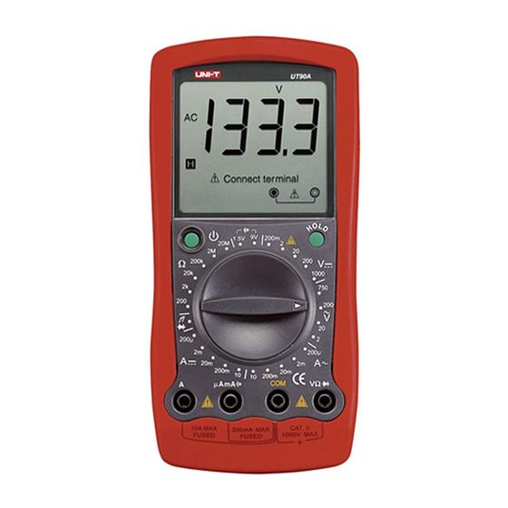
Model UT90A: OPERATING MANUAL The Meter Structure (see figure 1) ( figure 1) 1 LCD Display. 2 Hold Button. 3 Rotary Switch. 4 Input Terminals. 5 Power Button. - Page 10 Model UT90A: OPERATING MANUAL AC Current Measurement Range from 0.1µA to 10A µ...
-
Page 11: Functional Buttons
Model UT90A: OPERATING MANUAL Functional Buttons Below table indicated for information about the functional button operations. voltage measurement. Turn the power on and off. HOLD l Press HOLD once to enter hold mode. l Press HOLD again to exit hold mode and the present value is shown. -
Page 12: Display Symbols
Model UT90A: OPERATING MANUAL Display Symbols(1) (see figure 2) mVV k M AmAA ( figure 2) Symbol Meaning The battery is low. Warning: To avoid false readings, which could lead to possible electric shock or personal injury, replace the battery as soon as the battery indicator appears. - Page 13 Model UT90A: OPERATING MANUAL Display Symbols(2) (see figure 2) Symbol Meaning Ohm. The unit of resistance. kilohm.1 x 10 or 1000 ohms. ,k ,M Megaohm. 1 x 10 1,000,000 ohms. Volts. The unit of voltage. mV, V mV: Millivolt. 1 x 10 or 0.001 volts.
-
Page 14: Measurement Operation
Model UT90A: OPERATING MANUAL Measurement Operation(1) A.DC Voltage Measurement (see figure 3) black ( figure 3) Warning To avoid harms to you or damages to the Meter from electric shock, please do not attempt to measure voltages higher than 1000V DC/750V AC although readings may be obtained. - Page 15 Model UT90A: OPERATING MANUAL Measurement Operation(2) l The LCD displays “1” indicating the existing selected range is overloaded, it is required to select a higher range in order to obtain a correct reading. l In each range, the Meter has an input impedance of approx.
-
Page 16: Ac Voltage Measurement
Model UT90A: OPERATING MANUAL Measurement Operation(3) B.AC Voltage Measurement (see figure 3) black ( figure 3) Warning To avoid harms to you or damages to the Meter from electric shock, please do not attempt to measure voltages higher than 1000V DC/750V AC although readings may be obtained. -
Page 17: Dc Current Measurement
Model UT90A: OPERATING MANUAL Measurement Operation(4) l The LCD displays “1” indicating the existing selected range is overloaded, it is required to select a higher range in order to obtain a correct reading. l In each range, the Meter has an input impedance of approx. - Page 18 Model UT90A: OPERATING MANUAL Measurement Operation(5) The measurement ranges of DC current are: 200.0 A, 2.000mA, 20.00mA, 200.0mA and 10.00A. To measure current, do the following: 1. Turn off power to the circuit. Discharge all high- voltage capacitors. Insert the red test lead into the AmA or 10A terminal and the black test lead into the COM terminal.
-
Page 19: Ac Current Measurement
Model UT90A: OPERATING MANUAL Measurement Operation(6) D. AC Current Measurement (see figure 4) black ( figure 4) Warning Never attempt an in-circuit current measurement where the voltage between terminals and ground is greater than 60V. If the fuse burns out during measurement, the Meter may be damaged or the operator himself may be hurt. - Page 20 Model UT90A: OPERATING MANUAL Measurement Operation(7) E. Measuring Resistance (see figure 5) black ( figure 5) Warning To avoid damages to the Meter or to the devices under test, disconnect circuit power and discharge all the high-voltage capacitors before measuring...
-
Page 21: Resistance Measurement
Model UT90A: OPERATING MANUAL Measurement Operation(8) The resistance ranges are: 200.0 , 2.000k , 20.00k , 200.0k , 2.000M and 20.00M . To measure resistance, connect the Meter as follows: 1. Insert the red test lead into the V terminal and the black test lead into the COM terminal. -
Page 22: Testing Diodes & Continuity
Model UT90A: OPERATING MANUAL Measurement Operation(9) F.Testing Diodes & Continuity Warning To avoid possible damage to the Meter and to the device under test, disconnect circuit power and discharge all high-voltage capacitors before testing diodes and continuity. Testing Diodes (see figure 6) - Page 23 Model UT90A: OPERATING MANUAL Measurement Operation(10) Note l In a circuit, a good diode should still produce a forward voltage drop reading of 0.5V to 0.8V; however, the reverse voltage drop reading can vary depending on the resistance of other pathways between the probe tips.
-
Page 24: Battery Test
Model UT90A: OPERATING MANUAL Measurement Operation(11) To test for continuity, connect the Meter as below: 1. Insert the red test lead into the V terminal and the black test lead into the COM terminal. 2. Set the rotary switch to 3. - Page 25 Model UT90A: OPERATING MANUAL Measurement Operation(12) Warning To avoid damages to the built-In fuse and the Meter, measure the specified battery type and power supply only. To carry out battery test, connect the Meter as follows: 1. Insert the red test lead into the AmA terminal and the black test lead into the COM terminal.
-
Page 26: General Specifications
Model UT90A: OPERATING MANUAL General Specifications(1) l Maximum Voltage between any terminals and grounding: Refer to different range input protection voltage. Fuse Protection : 315mA, 250V, fast of A mA terminal type, 5x20mm : 10A, 250V, fast Fuse Protection type, 5x20mm... - Page 27 Model UT90A: OPERATING MANUAL General Specifications(2) l Safety/Compliances : IEC61010: CAT. II 1000V, CAT. III 600V overvoltage and double insulation standard. l Certification...
-
Page 28: Accuracy Specifications
Model UT90A: OPERATING MANUAL Accuracy Specification(1) Accuracy: (a% reading + b digits),guarantee for 1 year. Operating temperature:18 C~28 Relative humidity:<75%RH. Temperature coefficient: 0.1 x (specified accuracy) / 1 A. DC Voltage Overload Accuracy Range Resolution Protection 230VAC 200mV 0.1mV (0.5%+2) -
Page 29: Dc Current
Model UT90A: OPERATING MANUAL Accuracy Specification(2) C. DC Current Overload Accuracy Range Resolution Protection 0.1 A 200 A Fuse 315mA, 250V, fast type, (0.8%+2) 10 A 5x20mm 20mA 0.1mA 200mA Fuse 10A, (1.2%+5) 10mA 250V, fast type, 5x20mm Remarks: l At 10A Range:... -
Page 30: Resistance
Model UT90A: OPERATING MANUAL Accuracy Specification(3) E. Resistance Overload Accuracy Range Resolution Protection (0.8%+3) + short-circuit the input terminals 230V rms (0.8%+3) 200k (1.2%+5) F. Diodes & Continuity Test Range Resolution Overload Protection 230V rms Remarks: l At Range: Open circuit voltage approximate 3V. -
Page 31: Maintenance
Model UT90A: OPERATING MANUAL Maintenance(1) This section provides basic maintenance information including battery and fuse replacement instruction. Warning Do not attempt to repair or service your Meter unless you are qualified to do so and have the relevant calibration, performance test, and service information. -
Page 32: Replacing The Battery
Model UT90A: OPERATING MANUAL Maintenance(2) Warning To avoid electrical shock or arc blast, or personal injury or damage to the Meter, use specified fuses ONLY in accordance with the following procedure. To replace the Meter’s fuse: 1. Turn the Meter off and remove all connections from the terminals. - Page 33 Model UT90A: OPERATING MANUAL 3. Remove the 3 screws from the case bottom, and separate the case top from the case bottom. 4. Remove the battery from the battery connector. 5. Replace with a new 9V battery (NEDA1604, 6F22 or 006P).
- Page 34 Model UT90A: OPERATING MANUAL...
- Page 35 Model UT90A: OPERATING MANUAL...
- Page 36 Model UT90A: OPERATING MANUAL Copyright 2001 Uni-Trend International Limited. All rights reserved. Manufacturer: UNI-TREND TECHNOLOGY(DONG GUAN)LIMITED Address: Dong Fang Da Dao, Bei Shan Dong Fang Industrial Development District, Hu Men Town, Dong Guan City, Guang Dong Province, China Headquarters: Uni-Trend International Limited...