
Related Manuals for Campbell 21X


Summary of Contents for Campbell 21X
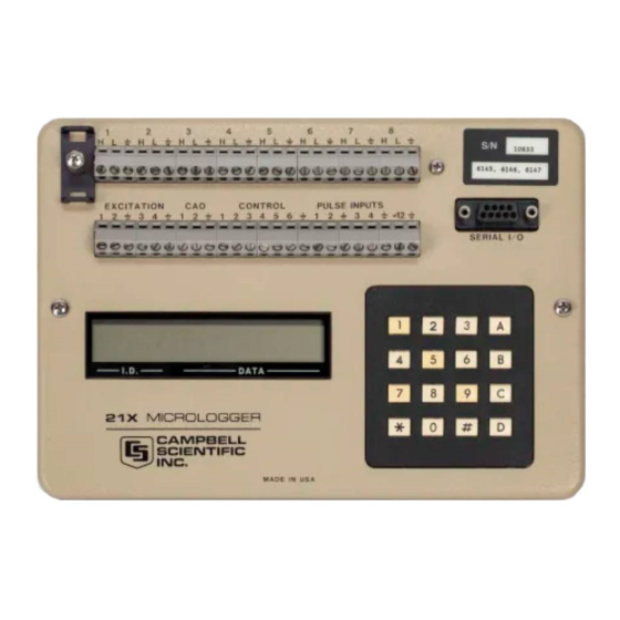
- Page 1 21X MICROLOGGER OPERATOR'S MANUAL REVISION: 8/95 sclENTlFlc, lNc. 1994, 1995 CAMPBELL CopynlcHT...
- Page 2 SCIENTIFIC, lNC.'s obligation under {thenrvise. Batteries have CAMPBELL unless specified or replacing (at CAMPBELL SCIENTIFIC, lNC.'s option) defective warranty is liririted repairing this products. The cugtomer shall assume all costs of removing, reinstalling, and shipping defective products S0lENT|FlC, lNC.
- Page 3 21X OPERATOR'S MANUAL TABLE OF CONTENTS PAGE WARRANW AND ASSISTANCE DETA1LS.... SELECTED OPERATING ..'....NOTES....'..CAUTIONARY OVERVIEW OV1. PHYSICAL DESCRIPTION Inputs OV1.1 .'..OV-2 Arlalog Outputs..OV1.2 ..'.'... OV-3 Switched Excitation Outputs OV1.3 OV-3 Continuous Analog ..OV1.4 OV-3 Control Ports...
-
Page 4: Table Of Contents
"8 and Option Cassette Tape .....4-4 ....Storage Module (SM192l716) ......4-6 Formats..Printer Output ..4-7 TELECOMMUNICATIONS Commands. Telecommunications ....5-1 21X..... Remote Programming .....5-3 PIN SERIAL INPUT/OUTPUT Description......6-1 Peripherals Enabling ....6-2 Peripherals....Transferto nterrupting Data Storage ...6-2 Peripherals. - Modem Telecommunications ....6-2... - Page 5 PROGRAMMING EXAMPLES PAGE REMENT PROGRAMMING EXAMPLES Pyranometer......7-1 Voltage Ll200S Silicon Supply ..7-1 with a Common External Power and Sensor Reference.......7-2 Temperatures Using 21X Probe ..7-3 Temperature Probe....7-3 Temperature and RH Output ..7-4 with Photochopper Ademometer Leads ....7-4 Tipping Bucket Rain Gauge with Long Bridge.
- Page 6 TABLE OF CONTENTS INSTALLATION INSTALLATION AND MAINTENANCE 14.1 14.2 14.3 Pane1s....'14.4 Solar ..21X.... 14.5 Direct Battery Connection to the ....Connections 14.6 Vehicle Power Supply ..Relays...,..of DigitalControl Ports for Switching 14.7 ....Grounding.. 14.8 ..14 Maintenance....
- Page 7 Commands (Sections 2.2.1 and 11\ for Program Control Instructions now available (Section The computations Point Format Floatirlrg 21X use floating point pedorfned the above PROMS includes floating point Revision 3 of arithnletic. CSI's 4 byte V high) V low,...
- Page 8 CAUTIONARY NOTES The sealed lead acid batteries Damage will occur the analog input 21XL are permanently damaged voltages excess of circuitry period. below 11.76 applied for a sustained Voltages discharged 2.5 Ahr capacitv will cause errors and rated at excess of storage.
- Page 9 3. I 21X Prompt Sheet capabilities. introduces concepts required to take advantage of 21X's Hands-on Overui$w This 21X will help the learning process, so don't programmin! examples OV4. in Section start Working with go ahead and you want just 21X and do them.
- Page 10 (Section etc. This control outputs, Figure OV1-2 shows the pin configuration as does NOT have the same 21X panel and the associated programming serial ports currently used on many instructions. personalcomputers. An SC32A is required to ANAIOG...
- Page 11 State rel{y coils (Section power 14.4). OV2.1 INTERNAL MEMORY 21X has 40,960 bytes of Random Access OV1.5 PULSE OOUNT INPUTS areas. Memory (RAM), divided into five four PULSE COUNT INPUTS measure five areas of RAM are: levelAC, or high frequency...
- Page 12 21X MICROLOGGER OVERVIEW INPUT/OUTPUT INSTRUCTIONS Sensor Specify the conversion of sensor signal to a value store data Input Storage. Programmable entries specify: measurement type number of channels measure input voltage range Control Input Storage Location sensor calibration constants used to...
- Page 13 21X MICROLOGGER OVER\NEW develop high level algorithms to - Final, processed values are used to Final process measurements prior to printer, tape, solid to Output stored for transfer (Section for retrieval via Processing state Module links. Values are stored OUTPUT PROCESSING INSTRUCTIONS...
- Page 14 21X MICROLOGGER OVERVIEW Table able Table Execute every x sec. Execute every y sec. Subroutines 0.0125<x<6553 <v<6553 ctions are executed nstru Table used if there is A subroutine is executed in the order sequentially need measure only when called from...
- Page 15 Output Processing Instructions to Enter the the exact action of a key ln some store processed data in FinalStorage. The the mode the 21X is in and depends the data are stored order which the mode the manual. described the order...
- Page 16 When Programs are entered into the 21X in one of example uses an instruction, find it four ways: Prompt Sheet and follow through the the parameters. Using the Prompt Sheet Keyed in using the 21X keyboard.
- Page 17 TURN ON THE POWER SWITCH AND this example measurements. temperaturel AS INDICATED PROCEED Display Shows (lD:Data) Explanation HELLO On power-up, the 21X displays "hello" while the memory. checks a few seconds delay after check. The result of the memory Each digit 11:111111 a memory socket on the CPU board.
- Page 18 Wait O1:21.423 The measurement will be updated every a new measurement is seconds when made. point 21X is measuring the temperature every 5 seconds and sending the value this Storage. to Input No data are being saved. nert have...
- Page 19 21X MICROLOGGER OVERVIEW Display Shows (lD:Data) Explanation 02:0000 the second Enter repetition and advance to which specifies the first lnput Storage parameter location to sample. O2:1 the panel lnput Storage location where temperature is stored. 04:P00 fourth instruction Enter location and advance to value is not entered into location.
- Page 20 21X MICROLOGGER OVERVIEW will be insefted that point the table, value then the new value Note that advance through and enter the parameters. untilA entered is keyed. The Instruction that was that point and instructions will be pushed down to...
- Page 21 Parameter For Example, the PC208 EDLOG similar to that used program. stored you have followed through sample program program in OV4.2, your 21X Parameter the Input Storage edited location to find the reference now has a 5 second execution interval and...
- Page 22 TC temp. 03:2 Location power-up year and day are initialized to the date 21X PROMs were assembled, the clock time. in the Mode (Section must to the current date and This is done 1.2).
- Page 23 02:0064 Exit *A, enter'0, Table :LOG compile commence logging data. OVs. 21X is rtow programmed to measure the DATA RETRIEVAL OPTIONS panel and temperatures every 5 seconds. There are several options for data storage and output: will be values Every hour tfrere retrieval.
- Page 24 21X MICROLOGGER OVERVIEW and exchanged for the one which this process for IBM PCIXTIATIPS-2's and retrieved so that data collection can compatibles. continue uninterrupted. Regardless of which method is used, Bring a storage device to the datalogger retrievalof data from the datalogger does NOT...
- Page 25 21X MICROLOGGER OVERVIEW DATA RETRIEVAL DATALOGGER €'g P5{) "3 RAOIO IRANSCEI\ER W,/ANTENNA & CABLE RADIO IRANSCEIVER VANTENNA & CAALE "":6'_.i coMPUTER RS-232 . ASn{CflRONOUS -J--...--...--J SERIAL CABLE coMuuNtcAlloNs PORT DATA REIREIVAL ARE NoE+ AODITIONAL METHOOS SATELUIE IRANSMISEON DUMP PRINTER DIRECT...
- Page 26 MICROLOGGER OVERVIEW OV6. SPECIFICATIONS oth€(tfl3€ speofied. unl$s tomparstrlta rsngc srsiatlt +SOoC vald folloriqg elecrical 3p€ctfica*mt TBANSIENT COT{DUCNVTTY RESISTANCE ANALOG INPUTS IIEASUREIIENTS uslng outrut connocoor'ls inDut ditterenria, CHANNELS: NUMBER OF llot) cooqE spark gaps connectod direcdy (0.04 ot tull scalo ACCUMCY: Eacfi dilleren0al channol can bo 0.035% singl$ended.
- Page 27 21X overruns the execution interval, finishes tables, table and waits for the next processing the inlerval. A third...
-
Page 28: Functional Modes
Table execution has priority over Table the PROMs were first released by Campbell Table 2 is being executed when it time to Scientific. To set the year, day,... -
Page 29: Compiling And Logging Data
Advance 1.3.2 DISPLAYING AND TOGGLING USER to previous location FLAGS then value, then A) lf D is keyed while the 21X displaying status of the user location value, the current current location and allow will be displayed the following format:... - Page 30 RESET TO ZERO. lnpuUOutput and Processing Instructions. The values stored in input locations may *6 Mode (Section the.0 The 21X should normally be left Mode displayed using the 1.3). data. when logging This Mode requires slightly...
- Page 31 The number of bytes O4:XXXX willtake for determines how long Final Storage in Program remaining willwrite to fill, at which point new data over old. memory (978 bytes total). will ERASE Entering 978 ALL MEMORY and put the the initial 21X through...
- Page 32 21X will block keyboard access to the the program tables have been determine *1,*2, *3, *4, Modes. Activated security altered. on power-up, the...
-
Page 33: Mode
ASCII). Commands Module or 2, and the *D ModQ. When *D is keyed, the 21X will can be executed via the only commands that telecommunications (Section display "13:00". will use the baud commands and 2, the 21X TABLE 1.8-1. - Page 34 SCAN RATE TABLE 1.8-4. Example Program Listing From *D Command LOAD PROGRAM FROM ASCII FILE the 21X to load a serial Command 2 sets MODE ASCII program. The format the same as sent SCAN RATE (Table 1.8.4). in response to command...
- Page 35 ^D^D can be sent to tell the 21X to entry so the buffer into the editor and reset the load signature. the complete file has been sent controlcodes which...
-
Page 36: Internal Data Storage
INTERNAL DATA STORAGE SECTION array. of 118 output For example, AREAS, OUTPUT FINAL 2.1-2 indicates that the Figure 18th D MEMORY POINTERS ARRAYS, the Output Flag instruction Table that portion of memory where high. Final stored. Data must be final, data TABLE PROGRAM... - Page 37 Then, during the next execution of High resolution data 4 byte format is a Instruction 96, the 21X outputs all the data with a maximum significant digits and between the PPTR and the DSP and updates...
-
Page 38: Displaying Stored Data On Keyboard/Display - *7 Mode
INTERNAL DATA STORAGE SECTION the low resolution format 0.0000305. A description of Campbell first (left floating point format may found reduced significant digits when the Scientific's greater (Table 2.2-2). Thus, the description the J and most) digit 7 or lelecommunications commands... -
Page 39: Instruction Set Basics
INSTRUCTION SET BASICS SECTION 21X are divided into 4 types: lnput/Output (l/O), Processing, program used Control. l/O are used make measurements Output and Program lnstructions in input locations or to initiate analog or digital pott output. Processing store the lnput Storage locations and place the... -
Page 40: Voltage Range And Overrange
Select Voltages greater than greater than or equal to the full scale output of damage the 21X. 3.5-1. lnput Voltage TABLE Ranges and Codes Range Code Full Scale Range Resolution"... -
Page 41: Control
Output Interval is not an even may be minutes (24 hours), the last automatically set low al 21X. divisor Flags 144O table. the day will be less than the the program output interval... -
Page 42: Program Control Logical
SECTION BASICS INSTRUCTION SET high. flag is used to restrict sampling This PROGRAM CONTROL LOGICAL for averages, totals, maxima, minima, etc., to CONSTRUCTIONS times when certain criteria met. flag automatically set low the beginning Most the Program Control lnstructions have program table. - Page 43 THEN DO command 30 is only when the used. BOTH TRUE the above instructions is used without lf one the corresponding END, the 21X will display program. error 22 when compiling Error (e5) without being displayed if END is used...
-
Page 44: Instruction Memory And Execution Time
INSTRUCTION MEMORY AND the subroutine. EXECUTION TIME Subroutine calls as nesting with count The standard 21X has 978 bytes of program instructions. They have a separate the above the programs entered memory available fbr *3 program *2, and nesting limit of seven (lnstruction 85, Section tables. - Page 45 SECTION INSTRUCTION BASTCS TABLE 3.9-2. Processing Instruction Memory and Execution Times = No. Reps. MEMORY INTER. PROG. INPUT LOC. BYTES (ms) EXECUTION TIME LOC. Z=Z+1 Z=X+Y ZaX+F Z+X-Y ZaX*Y ZJX*F Z+XN zlsoRr(x) 12.O zllN(x) z+EXP(x) Z+1/X Z+ABS(X) Z+FRAC(X) Z+lNT(X) Z+X MOD 13.3 Z4XY z+SrN(x)
- Page 46 SECTION SET BASICS INSTRUCTION 3.9-3. Output Instruction TABLE Memory and Execution Times Reps. = No. MEMORY INSTRUCTION (ms) EXECUTION TIME FINAL INTER. PROG. FLAG FLAG HIGH LOC. VALUES1 BYTES 2+9R (2,3, WIND VECTOR Options 00, 01, 02 + 17.5R Options 10,11,12 + 30R 70 SAMPLE...
-
Page 47: Error Codes
Compile errbrs are errors be reported to Campbell bug and should the program is keyed which are dqtected once 21X keeps track of the number of Scientific. time (*0, *6, or *B and compiled for the first occurred. The to 99) that E08 has times enterefl). -
Page 48: External Storage Peripherals
96 When 5M716 Storage Module tellwhether or not 5M192 21X will not send data if the Storage these Storage Modules, used data to one send connected (Section 4.4.2). Module is Enter Instruction 96 to enable the on-line... - Page 49 '19,296 days. divided by 491 39.3 Therefore, (e.9., "10" means tape would have to the 21X visited every 39 days enabled, printer disabled) to retrieve data, because write-over would begin 02:XX Baud Rate Code the 40th day. Output Enable Codes...
-
Page 50: Entering A
Instruction 96 or the enabled When on-linb, the 21X dumps data to tape *4 Mode, entering *9 will stop On-line printing Storage locations. blocks of 51P Final Residual be re-enabled if no keyboard entries are... -
Page 51: Cassette Tape
(window 2) changed while The Model RC35 Cassette Tape Recorder or will be set to its previous value when the TPTR equivalent can be left attached to the 21X for exited. Mode Changing the program and data recording or continuous on-line... - Page 52 SECTION EXTERNAT 21X has only necessary interface POWER SUPPLY special software for transferring programs via 21X's irjternal power supply will power the tape (Appendix ng periods of data transfer, but will recorder durf to play, advance, or back-up NOT be avaflable...
-
Page 53: Storage Module (Sm192L716)
The File Mark separates For example, DSP localion. you retrieve data from one 21X, disconnect the Storage Module and connect second 21X, The File Mark allows the operator to distinguish a File Mark is placed data. -
Page 54: Printer Output Formats
Ii RETURN, LINE FEED [''i'3^frFi^%, 05-0.100 07+0.000 05+2203. 04+0.000 +0101. 02+0011. I 06+2.0410 08+0.0000 09-0.001 11+6999. 10+.00001 12+99999. lllll-- REn RN, LINE FEED CARRTAGE -MAx DATA DATA DATA LO RE$ DATA output ,,GURE 4.5-1. Example of 21X Printable ASCII Format... -
Page 55: Telecommunications
TELECOMMUNICATIONS SECTION computer to retrieve data directly from Final Storage and may be allows realtime. Any user communication with 21X and monitor sensor readings in used 21X keyboard is through a computer or terminal instead of 21X that use of... - Page 56 21X via the return a other modem interface (Section 6.5). SC32A or Commands Telecommunications The 21X sends ASCII data with 8 data bits, Table. The the following Data Storage parity, plus one start bit and one stop bit.
-
Page 57: Remote Programming Of The 21X
:SSIC [YR:DAY:HR: assumed; colons means DAY:HR:MM:SS. the time string, HR:MM:SS ^,r|" time is unaltered. 21X returns year, Julian day, the C lf only entered, Checksum: Y:xx Dxxxx Txx:xx:xx Cxxxx hr:min:sec, and the MPTR is advanced to the next start of array. - Page 58 State, use "6 (Section Remote Keyboard step back and forth between the willshow The 21X display "LOG" when Telecommunications Command State and the executed via telecommunications. lt will not Remote Keyboard State. indicate active tables (enter "0 via the keyboard and the display will show the tables).
-
Page 59: Pin Serial Input/Output
(0V) logic are received on pin spacing (5V) standard high Enable: Raised by Modem ASCll, asynchronous 21X after the ring line has data bits, no parity, start been raised. stop bit, 300, 1200, bit, 76,800 baud (user 9600, selectable). -
Page 60: Peripherals
21X. When a modem raises the Ring line, the 21X line. responds by raising the ME 21X must Modem Enable (ME), pin 5, is raised to enable be sent... - Page 61 21X's ring line when it receives raises the frpm the computer or terminal, and characters PIN = 25-pin connector number conveds the 21X's logic levels (0V logic low, 5V function name ABR = Abbreviation for the logic high) td RS232 logic levels. terminalto...
- Page 62 The ASCII standard defines an alphabet the parity of the character correct. make consisting different characters where 21X ignores the eighth bit of that character each character corresponds to a number, letter, receives, and transmits the eighth bit as a bina symbol, or control code.
- Page 63 IF NOTHING HAPPENS terminal is sending or receiving characters, 21X is connected via the SC32A interface there is simple way to verify Set the duplex terminalior computer and * is not received full.
-
Page 64: Rement Programming Examples
Storage locations used the beginning of instructions dala. lt is unlikely that an application and 21X configuration exactly duplicates that assumed store the MEANTTO BE USED VERBATIM; SENSOR THESE EXAMPLES... -
Page 65: Reference
Typical current drain for a number thermocouple When meteris 300mA. When making measurements, are made at some distance from the 21X, it the 21X draws about 60mA. voltage Since to use a reference junction box often better equal to current... -
Page 66: Temperature Probe
TEMPERATURE AND RH PROBE temperatureF in Locations 2-6. excites and measures Instruction portion PROGRAM the Campbell Scientific 207 and Relative Humidity Probe. This Temperature a previously measured Temp 107 Probe instruction relies on temperatu temperature compensation... -
Page 67: Output
0.254 is used. 0.01632 m/s/rpm x 6 rpm/Hz x XHz + 0.2 m/s CONNECTIONS 0.0979 mls/Hz x XHz + 0.2 m/s There are times when the 21X is not able to the pulse counters at the exact time reset programmed. interval... - Page 68 However, neither resistance is likely found by connecting the correct multiplier circuit used to Figure 7.9-1 diagrams the entering lnstruction with a PRT to the 21X and PRT. The 10 kohm resistor allows then placed in an measure The PRT multiplier...
- Page 69 SECTION MEASUREMENT PROGRAMMING EXAMPLES fixed ohm resistor must thermally the example in Section 7.9, the excitation stable. lts precision is not important because voltage calculated the maximum exact resistance is incorporated, along with possible, yet allow the +50mV measurement that the PRT, into the calibrated multiplier.
- Page 70 MEASUREMENT PROGRAMMING EXAMPLES SECTION R" X'/(1-X') PROGRAM Where Wire Half Bridge )U1000 R3/(R2+R3) 50 mV slow Range value R"/Rs, lN Chan Thus, to obtain the calculating Instruction all reps w/EXchan for the temperature Excite OoC) the multiplier and offset used in lnstruction mV Excitation 430q respectively.
- Page 71 SECTION MEASUREMENT PROGRAMMING EXAMPLES The relationship between temperature and PRT and using lnstruction with a multiplier resistance one. a slightly nonlinear Instruction and an offset of 0, noting the readings ("6 computes this relationship for a DIN standard with water above the sensor and with PRT where the nominaltemperature coefficient...
- Page 72 O.4o/o temperature. Assume that degree C change ADJUSTABLE the load cell and the 21X lays the cable between COUNTER BALANCE the soil surface and undergoes a 25oC fluctuation. the resistance diurnal temperature the maximum temperature, then at...
-
Page 73: Wire Full Bridge
sEcTtoN MEASUREMENT PROGRAMMING EXAMPLES that it requires an extra differentialchannel counterbalance ounterbalance is readjusted and the offset and the added expense cable. wire :calculated to provide a continuous record this recalculated case, the benefits are worth the exp€nse. the water re water budget. -
Page 74: Block
7)12by changing Parameter Locations this example, the 21X is used to measure the lnstruction temperature of 5 Campbell Scientific 101 Probes (used with the CR21). 4, Excite, Instruction Delay, and Measure, is used because... - Page 75 0.147974 (units.01sec) Delay -2.18755E-4 2000 mV Excitation 2.19046E-7 1341E-10 Mult .001 2.33651E-14 Offset willonly The 21X allow significant digits to Polynomial the decimal point right or left to be entered Reps the keyboard. The polynomialcannot from X Loc .03: applied exactly as given the 101 manual.
- Page 76 MEASUREMENT PROGRAMMING EXAMPLES SECTION This measufement sequence should not be to me{sure temperature on the used probe. temperatur{ and The longer excitation/intpgration time could cause polarization df the RH element, shifting calibration. this example are the same The connectfons for for Example 7.5, where instruction 11 is used to measure hree...
-
Page 77: Probessing And Program Control Examples
AND PROGRAM CONTROL EXAMPLES PROCESSING Program Control intended illustrate the use of Processing and examples are of Output Processing lnstructions to lnput and the capability to direct results flags, Storage. as important as some of the techniques employed, for example: specific]examples may not be lnput Storage is used in the Running Average and Hainfall lntensity Directin|... -
Page 78: Intensity
SECTION PROCESSING AND PROGRAM CONTROL EXAMPLES Block Move time No. of Values minutes into Source Loc Temo i-8 First minute interval Source Step 0 (output) Set high Flag First Destin. Loc [:Temp i-9 Destination Step Set Active Storage Area Input Storage Area Array lD or location Set high Flag 0 (output) -
Page 79: Multiplexer
The port clocking the AM416 is pulsed. connected TCs and moisture blocks lf X<=>F are measured. X Loc 1Smin 21X sets the port controlling AM416 reset low. Soil moisture measurements are converted Then to block resistances. Set Active Storage Area... - Page 80 SECTION PROCESSING AND PROGRAM CONTROL EXAMPLES AM41 6 n;v- SETS 1_16 iCLK ----J/ iCOvt SETS 1_16 icov 8.3.1. 4M416 Thermocouple'and Soil Moisture Block Measurements FIGURE PROGRAM MULTIPLEXING EXAMPLE AC Half Bridge THERMOCOUPLES AND SOIL MOISTURE BLOCK 500 mV fast Range lN Chan Table 1 Programs Excite...
-
Page 81: Spm-Ao4 Analog Output Multiplexer To Strip Chart
AND PROGRAM CONTROL EXAMPLES' SECTION PROCESSING execution interval, but some longer Table by the interval. Mode Memory Allocation temperature (type Input Locations this example 02: 641 Intermediate Locations thermocouple) is measured every 0.5 seconds and the average output every 30 seconds. SUB 1 MINUTE OUTPUT INTERVAL Input Location Assignments: SYNCHED TO REAL TIME... - Page 82 Mult data. The weather SDM-AO4 may be used with Offset to provide an additional four continuous the 21X charts. The analog outputs for strip output Temp 107 Probe values this example are wind speed, wind direction,...
- Page 83 X Loc 0-540 WD be used to change a 0-360 degree algorithm you have 0-540 pot, input to 21X since the Wind Vector be used Then Do willwork with this output.) Instruction, Flag degrees to the 0-540 degrees,...
- Page 84 Input Storage locations tor the along with gives the 21X multiplier and offset. processed results. TABLE 8.7-1. Example Sensor Description and 21X Multiplier and Offset DESCRIPTION SYMBOL CALIB MULT SENSOR MEAS TYPE Wind prop Horiz.
- Page 85 AND PROGHAM CONTROL EXAMPLES SECTION PROCESSING TABLE 8.7-2. Example Outputs and lnput Storage Locations LEVEL OUTPUTS COVARIANCES LOC CORRELATIONS LOC VARIANCES LOC cR(wl,ul) cv(wl,u1) v(w1) M(w1) cR(w1,v1) cv(w1,v1) v(u1) M(u1) v(v1) M(v1) CV(W1,Tal) M(Tal) V(Tal) CV(W1 M(e1) V(e1) LEVEL 2 OUTPUTS VARIANCES LOC COVARIANCES LOC MEANS LOC...
- Page 86 SECTION PROCESSING AND PROGRAM CONTROL EXAMPLES Table 1 Programs WeUDry Bulb Temp Sec. Execution Interval Pressure Loc Dry Bulb Temp Loc Ta2 Panel Temperature Wet Bulb Temp Loc Tw2 [:Tw2 Loc [:PANL TEMP] Volt (SE) time Reps minutes into a 5000 mV slow Range minute interval...
- Page 87 8.8.1. interval and beginning of the atthe signat be determined by intervalcan endof the last to generate data The 21X was that 21X program flable looking two superimposed sine wave representing data". the "originaltime series generated and the 1.25H2 (amplitude_= signals, 1.25H2 signalbegan and ended at27O...
- Page 88 AND PROGRAM CONTROL EXAMPLES PROCESSING SECTION and 1.25H2 Signal 8.8-1. and lmaginary Results 0.25 TABLE FFT Real FFT Ii FFT Ri BIN # 0.02303 0.01036 0.009766 -0.00206 0.019532 0.029298 -0.00009 -0.00086 o.214852 0.0036 0.01096 0.224618 -o.c6277 -0.19328 o.234384 0.19439 0.59858 a.24415 -0.21391' -o.65827',...
- Page 89 AND PROGRAM CONTROL EXAMPLES PROCESSING SECTION Results Power SPectra TABLE Signal 1.25 Hz ZLoc:. 1025 FFT PSi 1.0859 ZLoc: 1026 0.214852 o.49212 o.224618 of Loop Beginning 84.'t52 o.234384 Delay o.24415 811.01 Loop Count 1024 980.79' 0.253916 162.4 0.263682 Z=SlN(X) 1.4764 o.273448 X Loc 1025...
- Page 90 Memory Allocation 01:1030 lnput Locations lntermediate Locations 8.8.2 EXAMPLE WITH BIN AVERAGING was used to generate data simulating The 21X from an ocean buoy with four wave data superimposed sine wave signals, 0.1, 0.125, O.2Hz. The 2048 generated samples 0.14, 0.t.t2...
- Page 91 AND PROGRAM CONTROL EXAMPTES SECTION PROCESSING Bin Averaging Results from Simulated Ocean Buoy Wave Data 8.8-4. FFT-o.1 FREQUENCY FFT-o.1 FREQUENCY 0.0507 0.00195 0.05265 0.0039 0.0546 0.00585 0.05655 0.0078 0.0585 0.00975 o.06045 0.0117 0.0624 0.01365 0.06435 0.0156 0.0663 0.01755 0.06825 0.0195 0.0702 0.02145 0.07215...
- Page 92 SECTION AND PROGRAM CONTROL EXAMPLES PROCESSING When flag 2 is set the FFT is computed and the Polynomial are sent to Final Storage. results X Loc lf Flag Loc: F(X) Then '87: FFT (OSX-2) Log(base 2) of Samples Power Spectra/Taper Log(base 2) Bins First Sample Loc...
- Page 93 AND PROGRAM CONTROL EXAII'IPLES PROCESSING SECTION Z=X MOD X Loc ZLoc: z=stN(x) X Loc ZLoc: Array (A.loc Scaling Loc: Start ZLoc'. of Loop Beginning Delay Loop Count Z=X+Y X Loc Y Loc ZLoc: Z=X*F X Loc ZLoc: 2841- P95l 21:. Table Mode Memory Allocation...
- Page 94 Both the high and low ranges and 5Oo/o ltheir frequency 2550 Hz and maximum input 21X's ground inputs mustlbe within of the the 16 bit option a maximum of 250 kHz. Commpn Mode Range in Section (see 13.2).
- Page 95 SECTION INPUT/OUTPUT INSTRUCTIONS count is incremented when the input 21X processor transfers Every 0.1 seconds, the voltage changes from below volts 8 bit pulse counters into the values volts. The above 3.5 maximum input accumulators (maximum count 65,535) voltage is volts.
- Page 96 INPUT/OUTPUT INSTRUCTIONS SECTION DELAY, AND MEASURE *** EXCITE, anywhere one second too short long. Pulses are not lost during almost twice so totalized values are correct FUNCTION wind speed but pulse information such as This instruction is used to apply an excitation value.
- Page 97 SECTION INPUT/OUTPUT INSTRUCTIONS PARAM. DATA The measurement sequence to apply an TYPE NUMBER DESCRIPTION voltage, excitation make two voltage measurements on two adjacent single-ended Repetitions channels, the first the reference resistor and Range code the second the voltage sensing wire from sensor (Figure 13.5-1), Input channel number for...
-
Page 98: Example 7.16
FUNCTION This instruction applies 4 VAC excitation wire full bridge (Figure 13.5- When used as to Campbell Scientific's Model voltage are made so that the conrtections Thermistor Probe, makes fast, single-ended the voltage drop across the full... - Page 99 RELATIVE HUMIDITY PROBE measurement Input location for first FUNCTION measurement This instruction applies 3 VAC excitation Multiplier across Campbell Scientific's Model 207 Offset Temperature and RH Probe, makes fast altered: single-ended measurement across series Input locations each the 150mV range, calculates the...
- Page 100 INPUT/OUTPUT INSTRUCTIONS SECTION TABLE 9-3. Thermocouple Type Codes Normal Measurement Tvpe Code Thermocouple (copper TC input from A5B40 isolation constantan) (use V range) E (chromel constantan) -99999 (chromel- common mode out of alumel) Output (lnst. J (iron only) constantan) Voltage and Temperature Ranges for Thermocouples if Reference Junction is 9-4i 20oC TABLE...
- Page 101 SECTION INPUT/OUTPUT INSTRUCTIONS **" TEMPERATURE OF INPUT PANEL the same as the signatures given Mode. Recording the signature allows of any program change FUNCTION or ROM failure. This instruction measures the temperature PARAM. the input panel. degrees Celsius DATA TYPE NUMBER DESCRIPTION PARAM.
- Page 102 INPUT/OUTPUT INSTRUCTIONS SECTION voltage ranges are practical (range and greater DELAY EXCITATION WITH codes 13-15). FUNCTON from excitation Excitation always supplied This instruction is used in conjunction with voltage in millivolts mfasuring a channel The excitation response timed others outputs. entered in Parameter excitation is not excitation using...
- Page 103 2 SM192 or number of scans made on the channels being SM716 Solid State Storage Modules (SM) at measured (the 21X multiplies the number 76.9K baud (parameter 4, Destination Option 1000). The entered measurements from C=2).
-
Page 104: Input/Output
Instruction 23 rsUTelecommu location table. the multiplier and raw data) determined by the first offset The 21X will not respond to attempts to enter calibration. fixed value determined by the telecommunications while Burst rements is a measu lected. - Page 105 SECTION INPUT/OUTPUT INSTRUCTIONS when done Table to read the timer will store instruction measuring. the elapsed time since the timer was reset Trigger option Table Trigger immediately Elapsed time tracked 0.1 second Trigger above integer. increments but displayed as an limit (high) time example, a 20 second elapsed...
- Page 106 INPUT/OUTPUT INSTRUCTIONS SECTION *lnput configuration; The SWSA addressed by the datalogger, allowing multiple SWSA's to be connected to one channels 8,7,6,5 *lnput configuration; datalogger. addresses are available. channels 4,3,2,1 **Function; channels 8,7,6,5 lf more channels are requested than exist in one **Function;...
- Page 107 SECTION INPUT/OUTPUT INSTRUCTIONS the SW8A does not respond, -99999 will SDM-CD16 loaded into input locations. Modules which do not respond when addressed the datalogger The SDM-CD16 Control Port Expansion wired or addressed incorrectly. Verify digitalcontrol ports with drivers. Each that the address specified in Parameter port controlled by a datalogger...
- Page 108 PROCESSING INSTRUCTIONS SECTION 33 X+Y facilitate qross referencing, parameter pre keyed to the values given on descriptions SHEET. the PROMPT These values are FUNCTION to the value defined as fdllows: Add the value in lnput location location Y and place the result in location = User sflecified input location number PAR.
- Page 109 Y and place the result in location Input location of for EXP(X) Division by will cause the result to be set to Dest. input location the maximum 21X number (+99999 positive, altered: Input locations 99999 negative). 42 l/X PAR. DATA TYPE...
- Page 110 SECTION PROCESSING INSTRUCTIONS *** 43 ABS(X) **' PAR. DATA NO. TYPE DESCRIPTION FUNCTION Input location of value in location Take the abbolute value divisor placelthe result in location Fixed X and X MOD Dest. input location for PAR. DATAI altered: Input locations TYPEi DESCRIPTION ;1Y ***...
- Page 111 SECTION PROCESSING INSTRUCTIONS Parameter cannot be entered as an indexed PAR. DATA NO. TYPE location within a loop (lnstruction 87). To use DESCRIPTION Instruction a loop, enter Parameter within fixed location and follow 49 with Instruction Swath lswA 31 (Move Data).
- Page 112 -.00486 *** 55 POLYNOMIAL **i sTH ORDER the SVPW derived by lnstruction where This relationship derived by.Campbell FUNCTION from the equations for the SVPW and polynomialof the form. Scientific Evaluate a Slh order the SVPI given in Lowe's paper. X+C2X2+C3X3a94X449515 F(X)=9919 PAR.
- Page 113 IPRESSURE] 02: 4 Input location no. of dry-bulb temp. Rf[)V(1-X)], where X the value derived rEMP.l standard 21X Bridge Measurement Programs 03: 4 lnput location no. wet-bulb (with appropriate multiplier and otfset, Section temp. TEMP.] 13.5) and represents...
- Page 114 After the IEEE, Vol. 66, No. Harris, Proceedings of this location will contain the first January 1978. taper is used, the 21X When the spectral bin or bin average by multiplying the results by applies correction result.
- Page 115 '128 when it sampled at frequency Hzlor 1024 samples, the frequency NOTE: The 21X has 1 lntermediate that is not available for use Location 1024< fi < 128 * " 1024 by Processing or Output Instructions...
- Page 116 (seconds). arctan (l;/R;) When the FFT results are expressed terms of calculatelthe magnitude and phase the 21X's the power spectra, a multiplier of will cause first compute the real and allthe very nearly must the average of...
- Page 117 SECTION PROCESSING INSTRUCTIONS For example, given that the power spectra result APS'=(X PS;+O.5(PSn4_4y2+PSn4*ed),ln shows that the energy peak of a signal falls where from nA-(A/2-1) to nA+(A/2-1) goes bin 32 when it sampled at frequency Hzlor 1024 samples and that the bin averaging table illustrates how The following...
- Page 118 Number of correlations desired Number The instruction does not conform to the 21X's samples Number of input types. four instructfon Data located in Input averaging period Storage is processed, and...
- Page 119 SECTION PROCESSING INSTRUCTIONS TABLE 10-2. Maximum Number of Outputs and Output Order for K lnput Values. (The output order flows from left to right and from top to boftom) INPUTS: )<2 MAX NO. OUTPUTS OUTPUTS (2nd) (3rd) (Kth) TYPE (1st) (4th) Means M(X1)
- Page 120 Overrun output. The rate which The occurrence of desired fina (see Section 2.1 of 21X Operator's Manual) can be made, the input values noted by decimal points on either side MODE). This the omission in LOG results in...
- Page 121 INTERMEDIATE STORAGE REOUIREMENTS measurement instruction to another. The number of Intermediate locations will ln many situations, the 21X must perform depend upon the number of input values and measurement and processing tasks in addition outputs desired: to those associated with the CV/CR Instruction.
- Page 122 OUTPUT PROCESSING INSTRUCTIONS of horizontal wind WIND VECTOR Standard deviation calculated as fluctuations from sub-intervals follows: FUNCTION 6p processes the primary variables Instruction either polar ...+1 oo*)2)/MJ1/2 and direction from o(o)=[((oo1 )2+(c@2)2 (wind speedland direction) or orthogonal (fixed propellers) sensors. lt East and uses the standard deviation over the...
- Page 123 @;)/N Standard deviation wind direction, o(@u). 1Jn=(XS;Cos @;)/N calculated using This standard deviation the case of orthogonal sensors: Campbell Scientific's wind speed weighted algorithm. us=(XUei)/N Un=(tUn,)/N the Resultant mean horizontalwind is not recommended for straight- direction Resultant mean wind direction,...
- Page 124 SECTION 11. OUTPUT PROCESSING INSTRUCTIONS ** 71 which selected by entering the AVERAGE information, for Parameter appropriate code FUNCTION PAR. DATA This instructibn stores the average value over NO. TYPE the given oulput interualfor each input location DESCRIPTION specified. Repetitions Time of maximum (optional) PAR.
-
Page 125: Measurements
OUTPUT PROCESSING INSTRUCTIONS SECTION 11. (defined as the bin select value) within the user's option, the histogram may particular subrange total specified range. open. closed or The open form includes count the bin associated with each values below the lower range limit the first subrange is incremented whenever the value allvalues... - Page 126 19xx is Qutput MAXIMUM SAMPLE ON 20xx. will be output as The 21X 85, otherwis€ OR MINIMUM 2085. the year will require a PROM update year outpqt along with a 2 option day or...
- Page 127 SECTION 11. OUTPUT PROCESSING INSTRUCTIONS The output flag must be set each time The amplitude change between bins Instruction 80 is used. Instruction 80 must the upper limit of the smallest amplitude directly follow the instruction that sets the output 50/5 Cycles with an amplitude, A, less...
- Page 128 SECTION 11. OUTPUT PROCESSING INSTRUCTIONS *** 82 TIME More than ofre Rainflow Histogram can STANDARD DEVIATION calculated u$ing the Repetitions parameter. The of inpirt data, the size the mean and swath FUNCTION the low and high limits of the standard deviation (STD DEV) of amplitude difnensions, Calculate the input...
- Page 129 PROGRAM CONTROL INSTRUCTIONS 95, END. Allsubroutines must Instruction 12-1. Description Flag Table 3 (Subroutine Table). When placed a Program subroutine called by command Output Flag Flag Control Instruction, the subroutine is execuled, User Flags Flag then program flow continues with the instruction ntermediate Processing Disable Flag following that which called the subroutine.
- Page 130 21X delays next execution the input location is indexed, the interval and makes the second pass through the from all input locations are added to the values loop.
- Page 131 PROGRAM CONTROL INSTRUCTIONS SECTION the vapor Loop Example: Block The user hour averages TABLE Data 12.3. wet- and dry-bulb pressure lated from the Transform psychrometers. One of 5 measurement is also pressure Beginning of Loop for pse vapor pressure available Delay calculation.
-
Page 132: Time
sEcTtoN PROGRAM CONTROL INSTRUCTIONS lf X<=>F X COMPARED TO X Loc DAY >= FUNCTION This instruction compares two input locations Exit Loop true and, the result true, executes the specified Command. The comparison codes are given Table 12-5. Beginning of Loop PAR. - Page 133 Case instruction true, the V{ow<0.8 V). V; -0.5 This option Vchigh<Sr5 executed and at the next Instruction 83 21X PROMS released after July only exists With jumps to End Instruction 95 execution (OSX-{.1 3 and greater).
- Page 134 96 is used instead to activate the TELECOMMUNICATIONS tape, Storage Module, or serial port output. using Program Control Instructions to allow 97 is used to have the 21X initiate Instruction of Instruction 96 only execution certain times, telecommunications in response to certain the user can control when the output active.
- Page 135 DC112 Modem (Hayes compatible correct response is not received within the When commands) is specified, the following specified in Parameter the 21X will time commands are sent to the modem before the rtake calls. will repeat the continue...
- Page 136 SECTION PROGRAM CONTROL INSTRUCTIONS *** 98 CHARACTER *** SEND Instruction 98 is used to send character to printer. single parameter sets the baud and gives the decimal equivalent rate parity). character (sent as 8 bits, no example, to send the ASCII character control at 9600 baud, 2018 would be entered This instruction can be used to...
-
Page 137: 21X Measurements
(e.9., series of measurements Before making a 333pV). The resolution of 1/15,000 x 5V = prescribed by an lnput Instruction, the 21X one part in 7500. single-ende( measurement calibration measurement. The makes a calibration accomplished by measuring two... - Page 138 Measurement Sequence laboratory instrument (both plugged into AC power and referencing ground to outlet ground), to run a ground wire between the 21X Because a single-ended measurement it"is best circuitry. 21X ground, any difference...
- Page 139 THE EF ECT OF SENSOR LEAD 13.3 THE SIGNAL SETTLING LENGTH TIME analog input switched into the Whenever an 21X measurdment circuitry prior to making finite amount of time measuremedt, to stabilize at correct required for signal the signal settles which value.
- Page 140 Figure 13.3-4 a representation the resistance from the 21X input through this capacitance, Cn, usually specified as external paths back to the 21X. Figure 13.3-2 pfd/ft. C* the sum...
- Page 141 PVC cable jackets are permissible jackets don't contribute to the lead since the capacitance because the jacket is outside the shield. Campbell Scientific uses only polyethylene and polypropylene insulated sensors (see Table 13.3-2) conductors since these materials have negligible dielectric absorption.
- Page 142 L=500 3600 2700 13.3-6. Resistive Half Bridge FIGURE Table 13.3-3 show that significant The values Connected to Single-Ended 21X Input error occurs at large direction values for leads feet. excess of 500 Instruction 4, Excite, the peak transient is linearly related...
- Page 143 0.1-1 5000 8641 1000 't-222 0-90 o24A 8771 constants are for 1000 foot lead lengths and include 3.3nfd 21X input capacitance. Estimated time Measured peak transients for 1000 foot lead lengths corresponding excitation, 13.3.4 SUMMAFY SETTLING ERRORS FOR transients because...
- Page 144 2000 feet is permitted for the Model corresponding to the error over the range 227 betore approaching the drive limitation. shown. TABLE 13.3-6. Maximum Lead Length vs. Error for Campbell Scientific Resistive Sensors Sensor Maximum Model# Error ve(pv) Range Length(ft.)
- Page 145 Scientifip 0.6oC 2OoC, 1.5oC piltails the lead 40oC. The error can be avoided by directly, the effect of the pigtails on the 21X end the signal must be resistanfe, maintaining considefed. Figure 13.3-9 shows extended leads because does not the bridge completion resistor,...
- Page 146 Thermistor Connected to YSf #44032 reference temperature. Showing: A) Large source resistance, source resistance at point B) large The 21X determines thermocouple C) configuration optimized for input settling temperatures using the following sequence. the reference junction First, the temperature SHIELD the reference junction measured.
- Page 147 21X from equilibrium at WITH 21X PANEL temperature of approximately 20oC. ambient After.100 minutes the gradient between the 21X parfeltemperature is measured with a temperature was still 15oC. batteries and air thermistor Fenwal Electronics UUT51 temperature in time rate of change...
- Page 148 VOLTAGE MEASUREMENT range. environmental other words, the junction, at reference is relatively close to OoC, The accuracy of a 21X voltage measurement temperature being measured, so the 0.1% (0.05% specified as 40oC) of full error (the product of the temperature absolute...
- Page 149 21X with voltage measured on an operating range, so there is error temperature due to environmental appropriate problem when the 21X is used as the reference few hundredths rements the voltage is a junction. junction boxes, External reference of a degree.
- Page 150 0.06"C. The temperature by is 25oC grade thermocouple wire to the thermocouples indicating 25.3oC, and the terminal that being used for measurement, and the 21X thermocouple connected cooler O.3oC the reference junction. panel used as than RTD.
- Page 151 MEASUREMENTS bridge measurements as well as supplying excitation to circuitry requiring differential are 6 bridge measurement instructions There measurements. This instruction does not software. the standard 21X Figure included reverse excitation. A the excitation before 13.5-1 the circuits that would typically be...
- Page 152 21X MEASUREMENTS SECTION RESULT INSTR. DIAGRAM DESCRIPTION DC HALF BRIDGE ENTERED WITH USER Rs+Rr SETTLING TIME BRIDGE HALF = =-= ALTERNATES EXCITATION K5*f(1 POLARITY FOR DEPOLARIZATION (f-3 WIRE tooo looo FULL BRIDGE Rr +Rz 2V2- WIRE v_-=- Vx-v1 HALF BRIDGE...
- Page 153 21X MEASUREMENTS SECTION for lead Wire Compensates Half Bridge wire resistance, assuming resistance same in both wires. Two single-ended measurements at each excitation polarity. Ratiometric output. Makes a ditferential Differential without Measurement measurement with Excitation reversing excitation 123456 polarity or switching...
- Page 154 SECTION 21X MEASUREMENTS TABLE 13.5-2. Calculating Resistance Values from Bridge Measurement Result Instr. lnstr. Muttiplier and Offset X=Vx(Rs/(R"+R1)) Mult. 1A/"; ofs. = R" '1-X/Vx Mult. Mult. 1A/"; ofs. = I rf -- Mult. 1/Rs tv)t(1-x/vx))/Rs X=Rr/(R"+R1) Mult. ofs. = R"=Rt- '1-X mult.
- Page 155 DC component from the excitation to return to 21X ground, path for affecting the measurement. can be lepresented by the model diagramme{ in Figure 13.6-2.
- Page 156 2"x5.5", outside dimensions are 21X). only, not thE 14"x1 18"x13.5"x8.13" (with brackets); weight is 11.16 lbs. TABLE 14.2-1. Typical Current Drain for Common 21X Peripherals Typical Current Drain (mA) Quiescent Active Peripheral RC35 Cassette Watt Radio 1350 PSO-VHF...
- Page 157 Typicalcurrent battery. voltages in excess of Input 21X peripherals are given for common Table 14.2-1 may damage the 21X and/or power supply. A transzorb provides transient protection by limiting voltage at approximately 20V. 14.3-1. Battery Pack and FIGURE Panel 14-2...
- Page 158 SECTION INSTALLATION AND MAINTENANCE 14.3.2 21XL LEAD ACID BATTERY 14.9 POWER 21X PqWER SUPPLIES SUPPLY 21X is {vailable with both alkaline batteries '12Y,2.5 21XL includes amp-hour lead (21XL). The (21X) and lepd acid batteries transformer (20V DC), and acid battery,...
-
Page 159: Direct Battery Connection To The
21X's TABLE 14.4-1. MSX5 Solar Panel MSX10 batteries are also pulled down causing an E08 Specifications started. -
Page 160: Grounding
600V. roughly 400 to be powerpd draws in excess of 75 mA at tempefature (limit of the 2N2907A room A modem/phone line connected to the 21X provides another path for transients to enter and 14-5... -
Page 161: Maintenance
When connecting an external battery to the 14.8.2 EFFECT OF GROUNDING ON 21X, use care to avoid shorting the +12V and MEASUREMENTS: COMMON MODE RANGE ground from the battery. common mode range voltage range, relative to the... - Page 162 Remove the obtalned. the aluminum cover plate screws hblding plate. Lay the 21X, cover remQve 21X's program, step 2, so that Change the panel a padded flat surface with dolrvn, Instruction 4, parameter 6 reads -4000 to cards and exposed as shown...
- Page 163 SECTION INSTALLATION AND MAINTENANCE 21X battery base and unplug Remove the shown at Location P10 on Figure 14.10-2. 21X. the battery from the Remove the four Connect the ground lead to any one of the screws holding the aluminum cover plate...
- Page 164 INSTALLATION AND MAINTENANCE SECTION *ffiqgffiililH F$ffik ffift; F-T8f--lfTt ffil rll:ll trg?'rrlirq lF.1i."J @ *o?++tffi+ffiHHFnffi @firFff,qD:7fl.-lu.l-11ff,-.' $ftffi$ftffift H[HHH[d,liJ o€ i< ll;l a> :l16l r*-1 ffffi$'THmHHHH I Es l. -,3. . 'F-ir-i-ili .t- .r '61' ffd-:fiil r-lg.gilJ [-H-i.!l-ij .t.r ,rcuRE cPU Board 14.1o-2.21x 14-9...
-
Page 165: Glossary
TIME: that actually Input Storage EXECUTIO$ The time the *6 Mode. thb 21X to execute an instruction or from takes group instructions. lf the execution time NUMBER: a pro$ram table exceeds the table's INSTRUCTION LOCATION... - Page 166 21X instructions, parameters are numbers intermediate calculations necessary for codes which are entered when operations, such as averages or standard programming the 21X to specify exactly deviations. Intermediate storage is not what the instruction Once the accessible to user.
- Page 167 THROUGHFUT: throughput rate a measurement can be made, rate at which engineering units, and the reading scaled tq Storage. 21X has the stored Final to]scan sensors at a rate exceeding ability thro{ghput rate (see SAMPLE RATE). priftary factor...
- Page 168 H4OIU and a hardware this is used. countries where 50 ls available for software. lf option When purchasing a new 21X, the user may select of 3 combinations of options are listed shipped. The differences between the default (OSX0) will be specified,...
-
Page 169: Binary Telecommunications
WITH BINARY terminated. The remaining bits are reserved. Description was set then "c" is lf the 2nd MSB in "b" loc.]F 21X sends, BINARY DUMP [no. port toggle byte, otherwise "c,d,...,n" are Storage Format (binary, Final each byte binary values each... -
Page 170: Format
J command, Final Storage represents Port 8, and so on to the least data in Campbell Scientific's binary format significant bit which represents Port1. requested by the J command, and terminating 00 HEX and two signature each input location requested bytes. - Page 171 Largest possible number without F|NAL STORAGE FORMAT is 7167, byte data fprmatted as either 2 byte LO but CAMPBELL SCIENTIFIC oi 4 values. The Resolution byte Hl Resolution delines the largest allowable range first two byteb of an output array contain code as 6999.
-
Page 172: Generation Of Signature
99.998% probability of detecting change Save the old high byte for later use. data or its sequence. The 21X calculates the signature using each transmitted byte except 2 byte signature itself. calculating the... - Page 173 BINARY TELECOMMUNICATIONS APPENDIX Sr(n) S1(n+1)= So(n) tpmporary byte by shifting the old Form sign{ture byte one bit to the left and which results from the carry bit adding opefation. A "shift left" is identicalto a shift bit resulting lgnore any carry multiply $y hdd.
-
Page 174: Ascii Table
ASCII TABLE APPENDIX American Standard Code for lnformation lnterchange Decimal Values and Characters (x3.4-1e68) Dec. Dec. Dec. Char. Char. Char. Dec. Ghar. CONTROL SPACE OONTROL A CONTROL CONTROL OONTROL qoNTRoL & QONTROL Qorurnol o GONTROL Oorurnol CONTROL CONTROL CONTROL CONTROL CONTROL CONTROL CONTROL... -
Page 175: Changing Ram Or Prom Chips
The new chip should be the unlikely event that a RAM chip free. chip allowable. the 21X can detect the bad chip during its the same the notched end installed with fails, direction as the other chips, to the right side of 1.5). -
Page 176: Changing Prom
Afterchanging PROMS, reassemble the 21X the power- power. Confirm that turn older 21X has iumpers at locations M15, check indicates that all PROMS and RAM E-l). and W27 (Figure With 8K RAM W2O, the *B jumpered good. - Page 177 APFENDIX DOCUMENTATION FOR SPECIAL SOFTWARE...
- Page 178 *D TAPE UPLOAD AND DOWNLOAD (Command The C20, with the format FUNCTION "ll, Decode" position, will read switches This library qption adds additional*D mode file. The PC201 will file read that allow datalogger programs to commands TAPE.COM program is run and the File Data loaded from cassette tape.
-
Page 179: Tables
Data Retrieval Sections in ..FUNCTIONAL MODES Mode Time Parameters in *5 ..,..'..' SQquence 1.2-1 Commands *6 Mode '.'.'.'..'.'. 1.3-1 21X......Allocation in Standard Mpmory 1.5-1 Data... D{scription of *A Mode ..'.. 1.5-2 Data... *B Mode ... D$scription of 1.6-1... - Page 180 1000 Foot Lengths Three Belden Lead Wires Scientific..Used by Campbell ....13.3-5 Summary of Input Settling Data for Campbell Scientific Resistive Sensors......Sensors 13.3-6 Maximum Lead Length vs. Error for Campbell Scientific Resistive ..13.3-7 Source Resistances and Signal Levels for YSI #44032 Thermistor Configurations Shown Wire..
- Page 181 14-1 14.2-1 ical ......14-3 icatAlkaline Battery Service and Temperature 14.3-1 Specifications ..'.'....". 14-3 12 LA Battery and AC Transformer 14.3-2 PanelSpecifications....and MSX10 Solar '.'-.-.-.'..'.14'4 14.4-1 21X PROM SIGNATURES AND SOFTWARE OPTIONS APPENDIX Signatures ..'.8-1 21X PROM LT.3...
- Page 182 Then/Else Execution 3.8-2 Construction ..'..3-5 LogicalAND Construction... 3.8-3 .-..'.'..'..3-5 LopicalOR EXTdRNAL STORAGE PERIPHERALS Format..4.5-1 E$mple of ASCII Output 21X Printable '.'.4-7 SERIAL INPUT/OUTPUT PIT| 6.1-1 Connector....'.'..6-1 9 Fin ....6.5-1 ..'.'..6-4 the ASCII Character Trqnsmitting UREMENT PROGRAMMING EXAMPLES L1200S..
-
Page 183: List Of Figures
LIST OF FIGURES 21X MEASUREMENTS 13.1-1 13.2-1 13.3-1 13.3-2 13.3.3 13.3-4 13.3-5 13.3-6 13.3-7 13.3-8 13.3-9 13.4-1 13.4-2 13.5-1 13.5-2 13.6-1 13.6-2 INSTALLATION AND MAINTENANCE 14.3-1 14.6-1 14.7-1 14.7-2 14.10-1 14.10-2 APPENDIX CHANGING RAM OR PROM CHIPS Memory Sockets on CPU Board... - Page 184 TNDEX * Modes, Average - flnstruction 711 11-1 Modes 1,(l example OV-l3 Programming 1O-2 running Probe Computing example 7-11 Probe finstruction exampfes 7-2,7-12 Battery power options ov-3 cells Alkaline 14-2 Probe finstruction 207 Relative Humidity External 14-4 Prograffiing example pack Lead acid 14-3 227 Soil Moibture Block...
-
Page 185: Fast Fourier
21X INDEX Clock (DPTR) Display Pointer CPU card circuitry calibration 14-7 Mode) Displaying/setting Clock ("5 Setting/displaying time ("5 Mode) Divide Programming example OV-14 flnstruction 381 10-2 protection CM6/CM10 Tripod grounding 14-6 X Mod 10-3 flnstruction Common mode range 13-2, 14-6... - Page 186 21X INDEX data Telecommunications flnstruction 801 11-5 nitiate Redirec{ing 12-6 exa{nple [lnstruction m{mory Input Storage Ring Altering Flags Changing size toggling Displayi(rg and Dalatormat 2-2 Disable Interme{iate Processing Definition OV-3 toggling (.6 Mode) Manually OV-10 Displaying Mode), Example Output with *0,...
- Page 187 Memory and execution Allocation Overranging analog inputs power-up Automatic RAM check on interval Overrunning execution Changing RAM or PROM chips E-l 21X OV-l Overview of Description of areas OV-3 Erasing Pointers Minimize 11-3 Parameter flnstruction Minus sign (-) & (--), Entering...
- Page 188 TNDEX RealTime 11-4 lnstructions Program 12-1 finstruction ov-5 example OV-13 Programming junction Compensation 13-10 parameter code 12-1 Reference Relays, Using digital ports for switching 14-5 Logical Probe,207 RH Probe times Relative Humidity execution Memory flnstruction 121 7-3, 9-6 meinory Program State Allocation Remote Keyboard...
-
Page 189: Wire Half
Programming Temperature from Platinum R.T.D. Spatial Maximum 10-3 flnstruction Minimum flnstruction flnstruction Spatial 501 10-4 example Programming 21X OV-l8 Specifications of Temperature from thermocouples, see Root Square 10-2 finstruction Thermocouple temperatu Slandard and Weighted Value Histogram Panel flnstruction Temperature of Input... - Page 190 Ranges/codes and overrange detection 3-2,9-1 WVector .rction 11-1 Watchdog WDT-VP 1&5 tion 11-3 Wind speed Vector finstruction Wind 11-1 example 21X's Wiring panel; Diagram of OV-2 " 10-2 flnstruction example Progranming 361 10-2 flnstruDtion 10-l flnstruction 10-1 ftnstruction 10-1 flnstruotion...