Table of Contents
Advertisement
Single Package Vertical Air Conditioning System
9-18K
L-B Suffi x, R410A Models
V(E, H)A09K25L-*
V(E, H)A12K25L-*
V(E, H)A18K25L-*
V(E, H)A24K25L-*
V(E, H)A24K75L-*
VPK-ServMan-L (4-11)
A
Series
(Electronic Controls)
V(E, H)A09K34L-*
V(E, H)A12K34L-*
V(E, H)A18K34L-*
V(E, H)A24K34L-*
V(E, H)A24K10L-*
24K
V(E, H)A09K50L-*
V(E, H)A12K50L-*
V(E, H)A18K50L-*
V(E, H)A24K50L-*
*Last Character May Vary
Advertisement
Table of Contents
Troubleshooting

Related Manuals for Friedrich VERT-I-PAK R410A


Summary of Contents for Friedrich VERT-I-PAK R410A
- Page 1 Single Package Vertical Air Conditioning System 9-18K L-B Suffi x, R410A Models V(E, H)A09K25L-* V(E, H)A09K34L-* V(E, H)A12K25L-* V(E, H)A12K34L-* V(E, H)A18K25L-* V(E, H)A18K34L-* V(E, H)A24K25L-* V(E, H)A24K34L-* V(E, H)A24K75L-* V(E, H)A24K10L-* VPK-ServMan-L (4-11) Series (Electronic Controls) V(E, H)A09K50L-* V(E, H)A12K50L-* V(E, H)A18K50L-* V(E, H)A24K50L-* *Last Character May Vary...
-
Page 2: Table Of Contents
Important Safety Information ... Introduction ... Vert-I-Pak Model Number Identifi cation Guide ... Serial Number Identifi cation Guide ... Electrical Requirements ... Chassis Specifi cations ... Cooling Performance Data ... Extended Cooling Performance ... Electronic Control Features ... Electronic Control Sequence of Operation ... Low Voltage Interface Connections ... -
Page 3: Important Safety Information
IMPORTANT SAFETY INFORMATION The information contained in this manual is intended for use by a qualifi ed service technician who is familiar with the safety procedures required for installation and repair, and who is equipped with the proper tools and test instruments required to service this product. - Page 4 Never operate the A/C unit with wet hands. • Use air conditioner on a single dedicated circuit within the specifi ed amperage rating. • Use on a properly grounded electrical circuit only.
-
Page 5: Introduction
Failure to follow these instructions can result in fi re and minor to serious property damage. • WATER DAMAGE HAZARDS: Improper installation maintenance, or servicing of the air conditioner unit, or not following the above • Safety Warnings can result in water damage to personal items or property. -
Page 6: Vert-I-Pak Model Number Identifi Cation Guide
MODEL NUMBER SERIES V=Vertical Series E=Cooling with or without electric heat H=Heat Pump DESIGN SERIES A = 32" and 47" Cabinet NOMINAL CAPACITY A-Series (Btu/h) 09 = 9,000 12 = 12,000 18 = 18,000 24 = 24,000 VOLTAGE K = 208/230V-1Ph-60Hz VPAK Serial Number Identification Guide SERIAL NUMBER AK = 2010... -
Page 7: Electrical Requirements
ELECTRICAL REQUIREMENTS WARNING ELECTRIC SHOCK HAZARD Turn off electric power before service or instal- lation. All electrical connnections and wiring MUST be installed by a qualified electrician and conform to the National Electrical Code and all local codes which have jurisdiction. Failure to do so can result in personal injury and/or death. -
Page 8: Chassis Specifi Cations
For VPAK Cool with Electric Heat 24K Electrical Data Heater Watts 2500/2050 3400/2780 Voltage Heating BTU/h 8500/7000 11600/9500 17000/13900 25598/20939 34130/27918 Heating Current (Amps) 10.9/9.9 14.8/13.4 Minimum Circuit Ampacity 17.2/15.9 22.1/20.3 Branch Circuit Fuse (Amps) LRA - Compressor (Amps) 34.8 34.8 Cooling Current (Amps) 10.0/10.4... -
Page 9: Cooling Performance Data
Cooling Performance Data ELECTRICAL RATINGS SERVICE DATA Cooling¹ Voltage Amps Supply Air VEA09K**RTL 230/208 VEA12K**RTL 230/208 VEA18K**RTL 230/208 VEA24K**RTL 230/208 10.0 VHA09K**RTL 230/208 VHA12K**RTL 230/208 VHA18K**RTL 230/208 VHA24K**RTL 230/208 10.6 ¹Test Conditions: 80º F, Room Air Temperature with 50% Relative Humidity, and 95º F, Outdoor Air Temperature with 40% Relative Humidity **Denotes Heater KW - Numbers Vary Extended Cooling Performance Data VEA - EXTENDED COOLING PERFORMANCE... -
Page 10: Electronic Control Features
ELECTRONIC CONTROL BOARD FEATURES The new Friedrich Vert-I-Pak has state of the art features to improve guest comfort and conserve energy. Through the use of specifi cally designed control software, Friedrich has accomplished what other Manufacturer’s have only attempted – a quiet, dependable, affordable and easy to use Vert-I-Pak. -
Page 11: Electronic Control Sequence Of Operation
Note: Unit is operated by a wired remote wall t-stat which is connected to an electronic control board at the VPAK unit. (Compressor Heat) Heat / Cool Units set point of the t-stat Heat Mode in Cool with Electric Heat Units When the t-stat is in the Heat Mode, if the indoor ambient temperature is below the heat set point, the fan turns on 5 seconds prior then the electric heat will turn on. - Page 12 Compressor Lock Out Time The lockout feature ensures that the compressor is de-energized for a period of time. The timer varies randomly from 180 to 240 seconds The compressor lockout is initiated every time the compressor is “off” due to: (1) Satisfying the T-stat temperature set point (2) Changing mode to fan only or heat (3) Turning the unit off...
-
Page 13: Low Voltage Interface Connections
Call for heating 24V Power from Electronic Control to Wall Remote Wall Thermostat All Friedrich Vert-I-Pak units are factory configured to be controlled by using a single stage heat/cool remote wired wall mounted thermostat. Thermostat Selection Friedrich recommends the use of the Friedrich RT4 and RT6. These thermostats are single stage heat/cool, manual changeover. -
Page 14: Service
Remote Wall Thermostat Location The thermostat should not be mounted where it may be affected by drafts, discharge air from registers (hot or cold), or heat radiated from the sun appliances, windows etc.. The thermostat should be located about 5 Ft. above the floor in an area of average temperature, with good air circulation. -
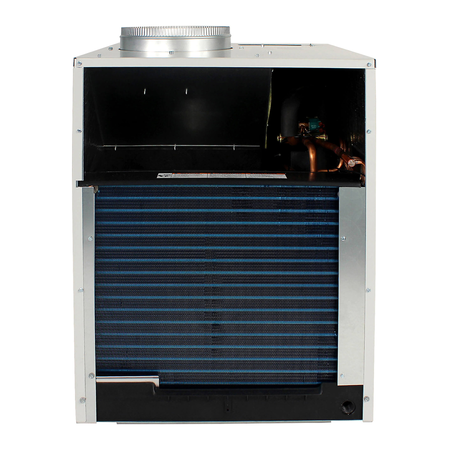
Page 15: Vpak 9-18 Btu Units Components Identifi Cation
COMPONENTS IDENTIFICATION Nameplate Air Discharge Ground Air Intake Front Side Right Side VPAK 9-18K BTU UNITS Blower Wheel and Heater in here 10” Duct Collar Condenser Heater Diagnostic Touch Pad Pullout Disconnect Compressor Blower/Fan Motor Capacitor Fresh Air Vent Evaporator Coil Condenser Coil Thermistor... -
Page 16: Vpak 9-18 Btu Units Components Identifi Cation
VPAK 24K BTU UNITS COMPONENTS IDENTIFICATION Air Intake Front Side Condenser Air Discharge Left and Back Sides Electric Control Panel 10” Duct Collar Return Air Filter Electronic Control Board Nameplate Fresh Air Door Lever Pull Out Disconnect Blower Wheel Compartment Evaporator Coil Thermistor Evaporator Coil... -
Page 17: Error Codes And Alarm Status
Error Codes and Alarm Status Unit Control Panel The display shown below has four digits. The left two digits indicate the error code # ( 1 to 24 ), The On/Off icons above these two digits indicate the currents state of the error code. The right two digits show the history count (up to 99) of the associated error code. -
Page 18: Components Testing
COMPONENTS TESTING Testing the Diagnostic Service Module Testing the Electronic Control Board WARNING ELECTRIC SHOCK HAZARD Turn off electric power before service or installation. Extreme care must be used, if it becomes necessary to work on equipment with power applied. Failure to do so could result in serious injury or death. -
Page 19: Electronic Control Board Components Identifi Cation
ELECTRONIC CONTROL BOARD COMPONENTS IDENTIFICATION AND TESTING (Continued) (See wiring diagrams pages 41-46) Front FP F2 F1 D2 D1 C GH GL B Y W R Low Voltage Interface Connection 1. Test for power at L1 and L2 for 208/230 VAC. (Ensure the transformer voltage selector switch is set for 230 VAC) 2. -
Page 20: Components Testing (Continued)
COMPONENTS TESTING (Continued) BLOWER / FAN MOTOR A single phase permanent split capacitor motor is used to drive the evaporator blower and condenser fan. A self-resetting overload is located inside the motor to protect against high temperature and high amperage conditions. WARNING ELECTRIC SHOCK HAZARD Disconnect power to the unit before... - Page 21 COMPONENTS TESTING (Continued) HEATER ELEMENTS AND LIMIT SWITCHES’ SPECIFICATIONS All heat pumps and electric heat models are equipped with a heating element and a limit switch (bimetal ther- mostat). The limit is in series with the element and will interrupt the power at a designed temperature. Should the blower motor fail, filter become clogged or air- flow be restricted etc., the high limit switch will open and interrupt the power to the heater before reaching an un-...
-
Page 22: External Static Pressure
External Static Pressure External Static Pressure can best be defi ned as the pressure difference (drop) between the Positive Pressure (discharge) and the Negative Pressure (intake) sides of the blower. External Static Pressure is developed by the blower as a result of resistance to airfl... -
Page 23: Fresh Air Door
Correct CFM (if needed): Chart B – Correction Multipli Explanation of charts Chart A is the nominal dry coil VERT-I-PAK CFMs. Chart B is the correction factors beyond nominal conditions. 1 ½ TON SYSTEM ( 18,000 Btu) Operating on high speed @ 230 volts with dry coil measured external static pressure .10 Air Flow = 450 CFM In the same SYSTEM used in the previous example but... -
Page 24: Refrigerant Sequence Of Operation
REFRIGERATION SEQUENCE OF OPERATION A good understanding of the basic operation of the refrigeration system is essential for the service technician. Without this understanding, accurate troubleshooting of refrigeration system problems will be more diffi cult and time consuming, if not (in some cases) entirely impossible. The refrigeration system uses four basic principles (laws) in its operation they are as follows: 1. -
Page 25: Sealed Refrigeration System Repairs
SEALED REFRIGERATION SYSTEM REPAIRS ANY SEALED SYSTEM REPAIRS TO COOL-ONLY MODELS REQUIRE THE INSTALLATION OF A LIQUID LINE DRIER. ALSO, ANY SEALED SYSTEM REPAIRS TO HEAT PUMP MODELS REQUIRE THE INSTALLATION OF A SUCTION LINE DRIER. EQUIPMENT REQUIRED: 1. Voltmeter 2. -
Page 26: Method Of Charging
Method Of Charging / Repairs The acceptable method for charging the RAC system is the Weighed in Charge Method. The weighed in charge method is applicable to all units. It is the preferred method to use, as it is the most accurate. The weighed in method should always be used whenever a charge is removed from a unit such as for a leak repair, compressor replacement, or when there is no refrigerant... -
Page 27: Overcharged Refrigerant Systems
After the unit has run 10 to 15 minutes, check the gauge pressures. Gauges connected to system with an undercharge will have low head pressures and substantially low suction pressures. Overcharged Refrigerant Systems Compressor amps will be near normal or higher. Noncondensables can also cause these symptoms. -
Page 28: Capillary Tube Systems/Check Valve
HERMETIC COMPONENTS CHECK WARNING BURN HAZARD Proper safety procedures must be followed, and proper protective clothing must be worn when working with a torch. Failure to follow these procedures could result in moderate or serious injury. METERING DEVICE Capillary Tube Systems All units are equipped with capillary tube metering devices. -
Page 29: Reversing Valve Description/Operation
REVERSING VALVE DESCRIPTION/OPERATION WARNING ELECTRIC SHOCK HAZARD Disconnect power to the unit before servicing. Failure to follow this warning could result in serious injury or death. The Reversing Valve controls the direction of refrigerant fl ow to the indoor and outdoor coils. It consists of a pressure- operated, main valve and a pilot valve actuated by a solenoid plunger. -
Page 30: Reversing Valve
When sluggish or stuck in the mid-position, part of the discharge gas from the compressor is directed back to the suction side, resulting in excessively high suction pressure. Should the valve fail to shift from coooling to heating, block the air fl ow through the outdoor coil and allow the discharge pressure to build in the system. -
Page 31: Compressor Checks
6. Protect new valve body from heat while brazing with plastic heat sink (Thermo Trap) or wrap valve body with wet rag. Fit all lines into new valve and braze lines into new valve. WARNING EXPLOSION HAZARD The use of nitrogen requires a pressure regulator. -
Page 32: External Overload
WARNING BURN HAZARD Certain unit components operate at temperatures hot enough to cause burns. Proper safety procedures must be followed, and proper protective clothing must be worn. Failure to follow this warning could result in moderate to serious injury. External Overload VPAK 9, 12, 18 K Btus With power off, remove the leads from compressor termi- nals. -
Page 33: Compressor Replacement
COMPRESSOR REPLACEMENT Recommended procedure for compressor replacement WARNING RISK OF ELECTRIC SHOCK Unplug and/or disconnect all electrical power to the unit before performing inspections, maintenances or service. Failure to do so could result in electric shock, serious injury or death. Be certain to perform all necessary electrical and refrigeration tests to be sure the compressor is actually defective before replacing. -
Page 34: Routine Maintenance
SPECIAL PROCEDURE IN THE CASE OF MOTOR COMPRESSOR BURNOUT WARNING ELECTRIC SHOCK HAZARD Turn off electric power before service or installation. Failure to do so may result in personal injury, or death. WARNING HIGH PRESSURE HAZARD Sealed Refrigeration System contains refrigerant and oil under high pressure. -
Page 35: Unit Performance Test Data Sheet
ROOM AIR CONDITIONER UNIT PERFORMANCE TEST DATA SHEET JOB NAME________________________________ TECHS NAME____________________________________ DATE: _______________ MODEL:_______________ SERIAL:________________ HOW IS ALL OF THE INSTALLATION? IS THE UNIT INSTALLED 2 3/8” INTO THE PLENUM? IS T H E F R E S H/E XA US T A IR V E N T OP E N ? ‘H’... -
Page 36: Thermistor Resistance Values
THERMISTORS’ RESISTANCE VALUES (This Table Applies to All Thermistors) FAHRENHEIT... -
Page 37: Troubleshooting Charts
ELECTRICAL TROUBLESHOOTING CHART - COOLING 9K BTU, 12K BTU, & 18K BTU SCENARIO 2 Compressor runs but Blower/Fan doesn't Compressor doesn't 24V at t-stat and defective control wiring control wiring? Problems indicated Is Line Voltage present at Motor Leads? Check Capacitor, is Replace Capacitor Capacitor Good? problem indicated. - Page 38 ELECTRICAL TROUBLESHOOTING CHART - COOLING Compressor and outdoor Indoor blower runs but fan motor run but indoor outdoor fan motor and blower does not run compressor do not run Defective t-stat 24V at t-stat and 24V at t-stat and defective control wiring control wiring? control wiring? or transformer...
-
Page 39: Electrical Troubleshooting Chart
ELECTRICAL TROUBLESHOOTING CHART Is Line Voltage Present at Solenoid Valve? Is the Solenoid Coil Good? Reversing Valve Stuck Replace Reversing Valve HEAT PUMP HEAT PUMP MODE SYSTEM COOLS WHEN HEATING IS DESIRED. Replace Solenoid Coil Is Selector Switch set for Heat? -
Page 40: Troubleshooting Charts
TROUBLESHOOTING CHART - COOLING REFRIGERANT SYSTEM DIAGNOSIS COOLING PROBLEM PROBLEM LOW SUCTION PRESSURE HIGH SUCTION PRESSURE Low Load Conditions High Load Conditions Low Air Flow Across High Air Flow Across Indoor Coil Refrigerant System Reversing Valve not Restriction Undercharged Moisture in System Defective Compressor TROUBLESHOOTING CHART - HEATING (HEAT PUMP) REFRIGERANT SYSTEM DIAGNOSIS HEATING... -
Page 41: Remote Wall Thermostat Wiring Diagrams
REMOTE WALL THERMOSTAT WIRING DIAGRAMS RT6 - Two Speeds Fan T-Stat - Field Provided -- -- -- Field Wiring LEGEND FOR AT WIRING HARNESS 24 VAC Power From Unit Common Terminal Call for Low Fan Call for High Fan Reversing Valve - Con gurable Cool mode, active reversing valve Heat mode, active reversing valve for VPAK heat pump unit Coil for Cooling... -
Page 42: Electrical And Thermostat Wiring Diagrams
COOL WITH ELECTRIC HEAT ELECTRICAL & THERMOSTAT WIRING DIAGRAM VEA 09/12/18 with 2.5 KW, 3.4 KW or 5KW ELECTRIC HEAT... - Page 43 HEAT PUMP WITH ELECTRIC HEAT ELECTRICAL & THERMOSTAT WIRING DIAGRAM VHA 09/12/18 with 2.5 KW, 3.4 KW or 5KW ELECTRIC HEAT BLACK...
- Page 44 COOL WITH ELECTRIC HEAT ELECTRICAL & THERMOSTAT WIRING DIAGRAM VEA 24 with 2.5 KW, 3.4 KW or 5KW ELECTRIC HEAT...
- Page 45 COOL WITH ELECTRIC HEAT ELECTRICAL & THERMOSTAT WIRING DIAGRAM VEA 24 with 7.5 KW and 10 KW ELECTRIC HEAT...
- Page 46 HEAT PUMP WITH ELECTRIC HEAT ELECTRICAL & THERMOSTAT WIRING DIAGRAM VHA 24 with 2.5 KW, 3.4 KW or 5KW ELECTRIC HEAT BLUE BLACK BLACK BLACK BLACK WHITE...
-
Page 47: Electrical And Thermostat Wiring Diagrams
HEAT PUMP WITH ELECTRIC HEAT ELECTRICAL & THERMOSTAT WIRING DIAGRAM VHA 24 with 7.5 KW and 10KW ELECTRIC HEAT BLUE BLACK BLACK BLACK BLACK WHITE... -
Page 48: Accessories
Accessories MODEL WALL PLENUM Two-part sleeve that telescopes in and out from 5 exterior wall penetration. VPAWP1-8 DIMENSIONS: 30 CUTOUT DIMENSIONS: 30 VPAWP1-14 Same as VPAWP1-8, but telescopes 8 to 14 as required. ARCHITECTURAL LOUVER Extruded aluminum louver that attaches to the outdoor section of the wall plenum. VPAL2 DIMENSIONS: 31 Same as VPAL2 but can be ordered in a special color to... -
Page 49: Warranty
Friedrich Air Conditioning Company - International Division. Any defective part to be replaced must be made available to FRIEDRICH in exchange for the replacement part. Reasonable proof must be presented to establish the date of install, otherwise the beginning date of this certificate will be considered to be our shipment date plus sixty days. - Page 50 2011 VPAK 9K-18K BTU/h Models...
-
Page 51: Vpak 9-18K Parts
2011 VPAK 9K-18K BTU/h Models... - Page 52 2011 VPAK 9K-18K BTU/h Models...
- Page 53 2011 VPAK 9K-18K BTU/h Models...
- Page 54 9K-18K BTU/h Models Part Number Part Descrip on 80074936 COMPRESSOR KIT 80074939 COMPRESSOR KIT 80074938 COMPRESSOR KIT 80074937 COMPRESSOR KIT 80077146 COMPRESSOR KIT 80023703 BASEPAN VPAK 80023702 BASEPAN VPAK 60179904 CONDENSATE DRAIN VALVE 01389903 TUBE CAP (Cooling) 03760473 TUBE CAP (Cooling) 01389915 TUBE CAP (Cooling) 01389985...
-
Page 55: Vpak 24K Parts
2011 VPAK 24K BTU/h Models... - Page 56 2011 VPAK 24K BTU/h Models...
- Page 57 2011 VPAK 24K BTU/h Models...
- Page 58 2011 VPAK 24K BTU/h Models...
- Page 59 24K BTU/h Models Part Number Part Descrip on 80077118 COMPRESSOR KIT 80103450 COIL, EVAPORATOR 80101261 COIL, CONDENSER 80101260 COIL, CONDENSER 61834800 STRAINER .312 COIL 61834801 STRAINER .375 COIL 03760548 TUBE CAP (Cooling) 03760507 TUBE CAP (Hea ng) 25076005 VALVE CHECK 60542007 FAN PLASTIC 16"...
-
Page 60: Technical Support/Contact Info
CUSTOMER SATISFACTION and QUALITY ASSURANCE Friedrich is a conscientious manufacturer, concerned about customer satisfaction, product quality, and controlling warranty costs. As an Authorized Service Provider you play a vital role in these areas. By adhering to the policies and procedures you provide us with vital information on each warranty repair you complete. - Page 61 FRIEDRICH AIR CONDITIONING CO. 10001 Reunion Place, Ste. 500, San Antonio, TX 78216 P 210-546-0500 | F 210-546-0731 www.friedrich.com Printed in the U.S.A. VPK-ServMan-L (4-11)