Audio Technica AT-MX341a SmartMixer Installation And Operation Manual
Four-channel automatic microphone mixer
Hide thumbs
Also See for AT-MX341a SmartMixer:
- Installation and operation manual (12 pages) ,
- Specifications (2 pages)

Related Manuals for Audio Technica AT-MX341a SmartMixer

Summary of Contents for Audio Technica AT-MX341a SmartMixer
- Page 1 AT-MX341a SmartMixer ® Four-channel Automatic Microphone Mixer Installation and Operation...
-
Page 2: Table Of Contents
Contents Introduction ........................3 ® ? ....................... 3 What is the SmartMixer Features ............................. 3 Front Panel ..........................4 Rear Panel ..........................5 Installation and Setup ....................6 Priority Microphones and Lockout Bus ................. 6 Preamplifier Gain ........................7 Output Gain ..........................7 Phantom Power ........................ -
Page 3: Introduction
SmartMixer application. However, all inputs and the output may be individually switched internally to achieve any combination of mic- and line-level input/output. See page 7 for details. What is the SmartMixer? The AT-MX341a SmartMixer ® Automatic Microphone Mixer is a microprocessor controlled, automatic switching, four-channel microphone mixer. -
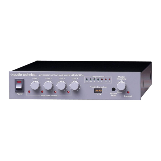
Page 4: Front Panel
AT-MX341a Front Panel 1. Power switch. 2. Power “on” indicator. 3. Input Gain controls. Adjust inputs for microphone sensitivities and/or operating conditions. 4. Selected Channel LED indicators. Indicate which channels are “on” or “active.” 5. Output Level LED meter. Indicates RMS output level of the mixer. “Zero” (0) level is factory calibrated for an output of +4 dBm into 600 ohms (Master Level control fully clockwise). -
Page 5: Rear Panel
AT-MX341a Rear Panel 1. Power input. Requires 12 volts AC or 15-18 volts DC, either polarity; 150 mA minimum. 2. Link In /Out. Provides for daisy-chaining of multiple mixers when more than four microphones are used. 3. Control Voltage Out. Provides 0 to +4 VDC (active high) to trigger external devices such as speaker switching, camera switching and indicator lights. -
Page 6: Installation And Setup
Installation and Setup AT-MX341a SmartMixer setup tips: 1. Turn Master Threshold control to minimum threshold, immediately clockwise of the “Manual” setting. 2. Set all Priority DIP switches to “down” position. 3. Turn all four microphone Gain controls fully counter-clockwise. 4. Connect the AC adapter to the mixer and plug in to outlet. -
Page 7: Preamplifier Gain
Mode 2…All Priority Pre-select switches Down In this mode, only one mic at a time can be “on.” The lockout bus shuts down all other mics until the first speaker pauses. As soon as the controlling microphone goes silent, the lockout bus goes inactive and any other mic can come on. -
Page 8: Output Level Led Meter
Output Level LED Meter Rear Panel The Output Level LED meter is factory set to indicate RMS output. Should peak output indication be desired, simply unplug the unit, remove the top cover and change the setting of the switch designated on the circuit board by “SW16”... -
Page 9: Control Voltage Out
Control Voltage Out When a microphone channel turns “on,” as indicated by a Selected Channel LED on the front panel, the channel’s associated Control Voltage Out goes “high” (+4 VDC). This signal can be used to light indicator lamps, switch speaker zones on and off, select video cameras, etc. The control voltage should not be connected directly to an inductive load such as a relay coil, as damage to the mixer may result. -
Page 10: Daisy-Chaining Mixers
Daisy-chaining Mixers When more than four microphones are needed, it is possible to daisy-chain multiple SmartMixers together through the Link In/Out connectors on the backs of the units (Fig. 2). Connect Mixer #1 Link Out jack to Mixer #2 Link In jack, etc. Mixer #1 output contains only audio from the first four microphones;... -
Page 11: Specifications
Specifications † Input Impedance 4,000 ohms ......Line 30,000 ohms ......Output Impedance Line 200 ohms... -
Page 12: Warranty
One-Year Limited Warranty Audio-Technica brand products purchased in the U.S.A. are warranted for one year from date of purchase by Audio-Technica U.S., Inc. (A.T.U.S.) to be free of defects in materials and workmanship. In event of such defect, product will be repaired promptly without charge or, at our option, replaced with a new product of equal or superior value if delivered to A.T.U.S.