Advertisement
Quick Links
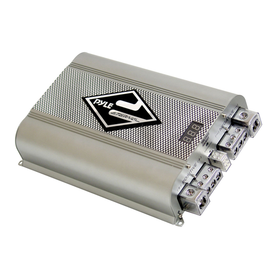
Model: PLCAPE500
50F Hybrid Super Cap (carbon and eletronic capacitor)
With Blue Digital Voltage Display
Capacitance ............................................. 50,000,000 micro farad (50
Farad)
Working Voltage ........................................... 16DC
Surge Voltage ................................................ 18DC
E.S.R. (Equivalent Series Resistance)------ 0.0015 ohm @120hz/ 25°C
Capacitance Tolerance------------------------ ± 10%
a)
3 digits hi-end blue light display DC voltage meter that can measure
0.1 DCV range.
b) Reverse pole connecting PCB buzz warning function. If the capacitor is
connected incorrectly by reversing the positive and negative wires
during the installation process the PCB will issue a 45 second noise to
warn you.
c)
Hi-end platinum plated 100% brass solid parts and chrome plated metal
cover
d) Over voltage limit and low battery voltage limit warning. When the
system voltage peeks over 17.5 DCV or LESS than 10 DCV. The
buzzer on the PCB will issue an audible noise warning.
e)
Multiple small capacitance capacitors linked to provide the lowest
inner E.S.R. and largest moment discharge power.
DETAILED FEATURES:
1
Advertisement

Related Manuals for Pyle PLCAPE500


Summary of Contents for Pyle PLCAPE500
- Page 1 Model: PLCAPE500 50F Hybrid Super Cap (carbon and eletronic capacitor) With Blue Digital Voltage Display Capacitance .........……..50,000,000 micro farad (50 Farad) Working Voltage .......…….….. 16DC Surge Voltage ........……… 18DC E.S.R. (Equivalent Series Resistance)------ 0.0015 ohm @120hz/ 25°C Capacitance Tolerance------------------------ ± 10% 3 digits hi-end blue light display DC voltage meter that can measure 0.1 DCV range.
- Page 2 You must first attach the mounting tabs to the capacitor before mounting it. Use the supplied hardware shown in the picture to the right. Notice the small mounting screw hole in the capacitor chassis.
- Page 3 CHARGING THE CAPACITOR AND WIRING: The capacitor must be charged before connecting the Power and Ground cables to the capacitor. Failure to charge the capacitor will result in a large spark generated from the rapid inflow of current. To Charge the capacitor: 1.
- Page 4 To Discharge the capacitor: With battery power disconnected, place the light bulb or resistor across the capacitor’s positive and negative terminals until light goes out or for three minutes if using a resistor. ! ! ! !
- Page 5 " " " " One Year Warranty from the date of purchase. ## ## ## ##...