Advertisement
Quick Links
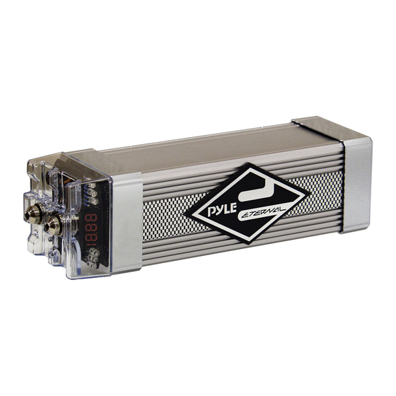
Model: PLCAPE30
3 FARAD DIGITAL CAPACITOR WITH RED DISPLAY )
Capacitance .................................................... 1,200,000 micro farad
Working Voltage ........................................... 21DC
Surge Voltage ................................................ 24DC
E. S. R. (Equivalent Series Resistance) .......... 0.0012 ohm @ 120hz/25
Capacitance Tolerance ............................. ±10%
We recommend at least 1 Farad of capacitance per 500 watts of amplifier output. This is a
general rule of thumb and may be adjusted up or down depending on the efficiency and design of the
amplifiers being used. There is no harm in having more than enough capacitance.
DETAILED FEATURES:
a) 4 digital 8 RED display voltage meter that can measure 0.01 DCV range.
b) Blue Light PCB
c) Over voltage limit and low battery voltage limit warning. When the system voltage peeks over
17.5 DCV or LESS than 10 DCV. The buzzer on the PCB will issue an audible noise warning.
d) Reverse pole connecting PCB buzz warning function. If the capacitor is connected incorrectly
by reversing the positive and negative wires during the installation process the PCB will issue
a 45 second noise to warn you.
e) Lowest E. S. R. 24 DCV foil with maximum moment discharge power in lowest E.S.R..
f) Hi-end chrome/black chrome/satin nickel plated finish solid capacitor casing.
Advertisement

Related Manuals for Pyle PLCAPE30


Summary of Contents for Pyle PLCAPE30
- Page 1 Model: PLCAPE30 3 FARAD DIGITAL CAPACITOR WITH RED DISPLAY ) Capacitance ...……... 1,200,000 micro farad Working Voltage ...…….….. 21DC Surge Voltage ...……… 24DC E. S. R. (Equivalent Series Resistance) ..…….. 0.0012 ohm @ 120hz/25 Capacitance Tolerance …………………..…… ±10% We recommend at least 1 Farad of capacitance per 500 watts of amplifier output. This is a general rule of thumb and may be adjusted up or down depending on the efficiency and design of the amplifiers being used.
- Page 2 To Charge the capacitor: 1. Make your connections from the Capacitor positive and negative output terminals to the amplifier(s) positive and negative terminals. Do not over-tighten the bolts on the Capacitor! Caution: Stripped terminals are not covered under the capacitor’s warranty. 2.
- Page 3 DISCHARGING THE CAPACITOR: WHEN YOU WANT TO MOVE THE CAPACITOR FROM THE ORIGINAL INSTALLED CAR AUDIO SYSTEM. YOU MUST FIRST DISCHARGE THE CAPACITOR USING THIS PROCESS BEFORE REMOVING THE CAPACITOR FROM THE CAR AUDIO SYSTEM. To Discharge the capacitor: With the battery power disconnected, place the light bulb or resistor across the capacitor’s positive and negative terminals until the light goes out or for three minutes if using a resistor.
- Page 4 Multiple Capacitor Wiring Diagram One Year WARRANTY APPLIES ONLY TO THE PRODUCTS SOLD TO CONSUMERS BY AUTHORIZED DEALERS IN THE UNITED STATES OF AMERICA OR ITS POSSESSIONS. OUTSIDE OF THE USA, ONLY THAT COUNTRY’S DISTRIBUTOR COVERS PRODUCTS PURCHASED BY CONSUMERS FROM OVERSEA AUTHORIZED DEALER.