
Related Manuals for Honeywell PCR-300


Summary of Contents for Honeywell PCR-300
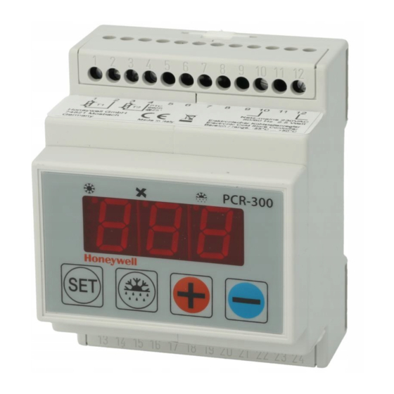
- Page 1 PCR-300 PCR-300 RC Installation and Operating Instructions Electronic refrigeration control...
-
Page 2: Table Of Contents
TABLE OF CONTENTS 11 Unpacking the unit and conditions of use 12 General instructions 13 Use and function 3.1 Use for the purpose intended 3.2 Function 14 Safety 4.1 Sources of danger 4.2 Safety precautions 15 Installation and commissioning 5.1 Mechanical installation 5.2 Electrical installation 5.3 Setting the DIP switch for the emergency setpoint and clock back-up battery... -
Page 3: Unpacking The Unit And Conditions Of Use
1 Unpacking the unit and conditions of use Before and when unpacking the unit, make a visual inspection to identify any possible damage which may have occurred during transportation. Please look for loose parts, dents, scratches, etc. Report any damage immediately to the freight company. (Please see “Conditions if damage has occurred”.) In other cases, the latest edition of the “General conditions for the supply of goods and services”... -
Page 4: Function
Alarm output. Defrosting is initiated via programmable intervals of time, max. 24/day. The PCR-300 RC is provided with a real-time clock with a back-up battery for defrost control. A maximum of six times per day can be programmed. -
Page 5: Safety Precautions
Never expose the unit to excessive heat, dust and vibrations. Avoid knocks and pressure loads. If the housing is damaged, there is a risk of an electric shock causing death or injury. If the unit cannot be operated without the risk of danger, it must be taken out of service and precautions taken so that it cannot be switched on again unintentionally. -
Page 6: Electrical Installation
a) housing with 2 mounting tabs: open out the lateral mounting tabs; clip the unit on the 35 mm rail and press tabs in again. b) housings with 1 mounting tab: put housing on the upper 35 mm rail. Clip the unit on the 35 mm rail, lower tab clips on the rail automatically. - Page 7 Terminal: Description: 1 - 2 = Cold store sensor 3 - 4 = Evaporator sensor 10 - 12 Mains = Power supply 13 - 15 = Compressor contactor (cooling) 17 - 18 = Evaporator fan (contactor) 20 - 21 Alarm = Remote alarm indicator; indicator lamp or contactor (with RC-element) 23 - 24 = Defrost heating...
-
Page 8: Clock Back-Up Battery
Setpoint value at –18 °C for emergency operation. Advisable for deepfreezers. For PCR-300 RC only: The back-up battery must be switched on when the controller is started up so that the real-time clock keeps operating if there is a power failure. -
Page 9: Operating Of The Controller
Note: It takes approximately 24 hours for the battery to achieve its full back-up capacity. The battery will provide cover for a power failure of approximately 1 month. 6 Operation of the controller Front view of controller: 6.1 Switching on the operating voltage The controller is started by means of a control switch provided by the customer. -
Page 10: Key Functions
Three spot indicators show the switching status of the relays during operation: Pos. 1: On : Compressor relay on. Off: Compressor relay off. Flashes: Compressor start-up delay E05 active. Pos. 2: On : Evaporator fan relay on. Off: Evaporator fan relay off. Pos. -
Page 11: Adjusting The Cold Store Temperature
Press and hold down the keys at the same time for approx. 5 seconds (E01 appears in the display for PCR-300 and E00 for PCR-300RC) Setting: Press and hold down the key. Adjust the setpoint value to the desired figure using the key. -
Page 12: Manual Defrost
If the set temperature difference E03 is negative, an alarm is given if it is too cold in the refrigerated area, e.g. E03 = –10 K, cold store setpoint = –18 °C alarm at –28 °C in refrigerated area. If the set temperature difference E03 is positive, the alarm is given if it is too warm in the refrigerated area, e.g. -
Page 13: Programming
Access to the second programming level: Press and hold down the keys at the same time for approx. 5 seconds (Display: E01 for PCR-300, E00 for PCR-300RC). key to select parameters. Setting: Press and hold down the key. Adjust the setpoint value to the desired figure using the key. - Page 14 The time is entered in increments of 10 minutes in each case . Important: The times must be entered in ascending order. Alarm temperature difference –50 K to + 50 K 20 K Delay time – Alarm 0 to 99 mins. 10 mins.
-
Page 15: Sensor Calibration (Parameters E15 And E16)
Sensor calibration T1 –5 to +5 K (cold store) Sensor calibration T2 –5 to +5 K (evaporator) Operation of 0 = Relay de-energizes compressor relay 1 = Relay is perma- if cold store sensor T1 nently engergized is defective 2 = Alternately ener- gized/de-ener- gized according to time set in E18... -
Page 16: Maintenance
8 Maintenance The controller does not require any maintenance. It does not have any fuses so, if brief voltage spikes occur, the refrigeration system will not stop operating for a prolonged period. Once the disturbance has passed, the controller will automatically start up again. Cleaning the housing: Only a dry anti-static cloth may be used to wipe clean all plastic parts. -
Page 17: Problem Solving
Clearing alarm: Press the key. All alarm messages, with the exception of AL2, are also reset by switching off the operating voltage. AL2 can only be reset using key. 10 Problem solving Fault Cause Remedy Evaporator fan does not Evaporator Refit switch on during sensor T2 has... -
Page 18: Technical Data
Storage temperature –20 °C to +80 °C Data back-up Non-volatile memory (EEPROM) Clock: Back-up battery, approx. 1 month power reserve (PCR-300 RC only) Emergency setpoint DIP switch under display cover selection (off = +4 °C / on = –18 °C) Sensor type –... - Page 19 IEC 730-1 (1986) ed 1 Automatic electronic controls Full technical documentation is available. Operating instructions for the device are provided. Mosbach, March 22 , 1999 Honeywell Flica Honeywell AG Hardhofweg D-74821 Mosbach i.V. Dr. Osthues R + D / Production Manager...
- Page 20 Division of Honeywell Technologies Sàrl, Hardhofweg • 74821 Mosbach / Germany Ecublens, Route du Bois 37, Switzerland Phone: +49 (0) 62 61 / 81-475 by its autorised representative Honeywell GmbH Fax: +49 (0) 62 61 / 81-461 E-Mail: Cooling.Mosbach@honeywell.com www.honeywell-cooling.com...