
Related Manuals for AMX Optima SD


Summary of Contents for AMX Optima SD
- Page 1 Instruction Manual Optima SD Distribution Matrix A u t o P a t c h M a t r i x S w i t c h e r s R e l e a s e : 4 / 2 1 / 2 0 0 9...
-
Page 2: Amx Limited Warranty And Disclaimer
Products repaired under this policy will carry a ninety (90) day warranty on material and labor. • AMX will notify the AMX Authorized Partner with the cost of repair, if cost is greater than the Standard Repair Fee, within five (5) days of receipt. -
Page 3: Software License And Warranty Agreement
LICENSE GRANT. AMX grants to Licensee the non-exclusive right to use the AMX Software in the manner described in this License. The AMX Software is licensed, not sold. This license does not grant Licensee the right to create derivative works of the AMX Software. -
Page 4: Table Of Contents
Product Notes ......................... 7 Front View ..........................8 Rear View ..........................9 Power Receptacle & Specifications..................10 Optima SD Specifications ...................... 12 Configuration Information & Control Options ............... 12 Installation & Setup ...................15 Site Recommendations ......................15 General Hazard Precautions ....................15 Unpacking.......................... - Page 5 Using BCS to Access System Diagnostic Information............. 64 Splash Screen Examples ......................65 Appendix C – Replacing I/O Boards ..............67 Removing I/O Boards......................68 Replacing I/O Boards ......................71 Updating the System Configuration ..................74 Optima SD Instruction Manual...
-
Page 6: Esd Warning
Grounding straps, conductive smocks, and conductive work mats are specifically designed for this purpose. Anyone performing field maintenance on AMX AutoPatch equipment should use an appropriate ESD field service kit complete with at least a dissipative work mat with a ground cord and a UL listed adjustable wrist strap with another ground cord. -
Page 7: Important Safety Information & Instructions
There are no user serviceable parts inside an AMX AutoPatch product; service should only be done by qualified personnel. If you see smoke or smell a strange odor coming from your AMX AutoPatch product, turn it off immediately and call technical support. -
Page 8: Information Et Directives De Sécurité Importantes
Placez uniquement des fusibles de calibre exact dans les boîtiers. Veillez à ce que la prise de courant soit proche de l’appareil et facile d’accès. Veillez à ce que votre appareil AMX AutoPatch soit installé sur une surface stable ou qu’il y soit fermement maintenu. -
Page 9: Notices
AMX. Copyright protection claimed extends to AMX hardware and software and includes all forms and matters copyrightable material and information now allowed by statutory or judicial law or herein after granted, including without limitation, material generated from the software programs which are displayed on the screen such as icons, screen display looks, etc. - Page 10 Warning: The icon to the left indicates text that warns readers against actions or conditions that could cause potential injury to themselves. Caution: The icon to the left indicates text that cautions readers against actions that could cause potential injury to the product or the possibility of serious inconvenience. Optima SD Instruction Manual...
- Page 11 Notices Optima SD Instruction Manual...
-
Page 12: Overview & General Specifications
For information, see the “APWeb Expansion Board” chapter (see page 45). Product Notes An Optima SD system is normally sold as a stand-alone product; however, it can be linked as part of a larger system, including any other AMX AutoPatch products that are XNNet compatible. All Optima SD systems have an integral control panel and can be controlled from a variety of other sources (see page 13). -
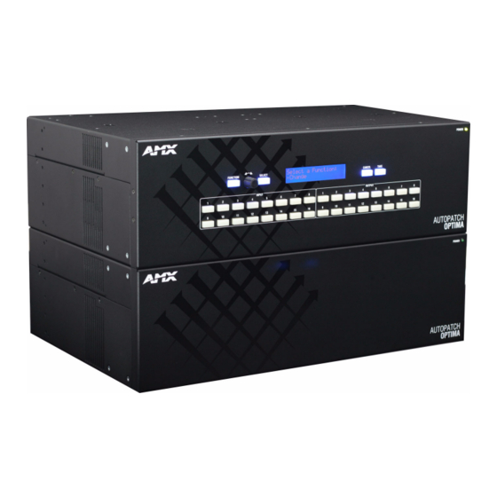
Page 13: Front View
Note: Features and specifications described in this document are subject to change without notice. Front View The enclosure is the structural basis of Optima SD systems. All Optima SD systems have an integral CP-15 Control Panel for controlling the system’s switches and system attributes. The control panel can also be used for system verification, redundant control, and troubleshooting. -
Page 14: Rear View
Output connectors Input connectors Power receptacle FIG. 2 Rear view 16x16 RGBHV+Stereo Optima SD system (RGB enclosure linked to HV with stereo enclosure) Rear View Components CPU/Control board Power receptacle and specifications Input/output boards (number of connectors will vary depending on the system’s configuration) -
Page 15: Power Receptacle & Specifications
FIG. 3 CPU/Control board in Optima SD enclosure Although primarily designed as a pre-engineered, stand-alone system, the Optima SD can be linked to other AMX AutoPatch Matrix Switchers. For information on linking between the Optima SD and other matrix switchers, see the instruction manual for the specific product. - Page 16 FIG. 4 Input/Output boards in an Optima SD enclosure An Optima SD (3 RU) enclosure has six board slots. The double boards each fill two board slots and have two rows of connectors. For information on the 500 MHz video, Hi-Z sync, and stereo audio boards included in your system, including connector types, cabling/wiring directions, and specifications, see the applicable board chapter in this manual (the chapter title specifies the board’s signal type).
-
Page 17: Optima Sd Specifications
Important: Unless you need to modify the system, you will not need to use XNConnect. A copy of the configuration file is provided on the AMX AutoPatch CD that is shipped with each system. The configuration software, XNConnect, is provided on the CD and can be used to further customize the configuration file (see “Appendix A –... - Page 18 Manual on the AMX AutoPatch CD or at www.amx.com. Third-Party Controllers A third-party controller can also be attached to an Optima SD enclosure. If using a third-party controller, see the controller documentation for operating instructions. Note: Advanced programmers who want to design their own control programs can use AMX’s AutoPatch XNNet protocol.
- Page 19 Overview & General Specifications Optima SD Instruction Manual...
-
Page 20: Installation & Setup
These recommendations address potential hazards that are common to all installations: Elevated Operating Temperature The maximum rated ambient temperature for Optima SD enclosures is 110° F (43° C). All equipment should be installed in an environment compatible with the manufacturer’s maximum rated ambient temperature. -
Page 21: Unpacking
AC line conditioner. Unpacking The Optima SD is shipped with one enclosure per shipping box. The invoice is sent separately; a packing slip is attached to the outside of each box. Each box contains the following items:... -
Page 22: Rack Installation & System Setup
Installation & Setup Rack Installation & System Setup The Optima SD enclosures can be mounted in a standard EIA 19 in. (48.26 cm) rack. Rack installation ears are included, and directions for mounting the rack ears are included in the rack installation instructions (see page 19). - Page 23 “Attaching Inputs & Outputs” starting on page 26. Do not apply power to the devices until after the Optima SD has power (Step 5). Optional – Establish communication with an external control device; see page 22.
-
Page 24: Linking Enclosures
Important: The ENC LINK (Ethernet RJ-45) connector on the CPU is not for a TCP/IP connection. As ordered from the factory, an Optima SD system is configured to operate as a stand-alone unit once the two enclosures are linked. The system is, however, still capable of being linked to other AMX AutoPatch Matrix Switchers. - Page 25 / enclosure numbers on the rear of each enclosure. Link Cable AMX provides an RJ-45 crossover link cable for direct linking between Optima SD enclosures. The cable is wired to TIA/EIA-568-A on one end and TIA/EIA-568-B on the other end.
- Page 26 Installation & Setup Linking an Optima SD System Optima SD enclosures are directly linked to each other via their ENC LINK ports (FIG. 8). The total distance between the two linked enclosures cannot exceed 100 ft. (30.5 m). Cable Length Requirements...
-
Page 27: Attaching External Controllers
Installation & Setup Attaching External Controllers The Optima SD can be controlled by attaching an external control device that uses one of the communication protocols listed below: BCS (Serial) – ASCII sent over a null modem serial cable via the CONTROL (RS-232) port XNNet –... - Page 28 (null modem) serial cable attached to the CONTROL (RS-232) port on the enclosure’s CPU. PCs are common serial controllers. Once a PC is attached to an Optima SD enclosure, the system can be controlled by running APControl software on the attached PC (see the AMX AutoPatch CD). The system can also be controlled by entering BCS commands into a terminal emulation program, such as HyperTerminal.
- Page 29 AC line conditioner. If not already on, apply power first to the Optima SD enclosures and then to the source and destination devices (see “Applying Power & Startup” on page 29).
- Page 30 Insert wires into REMOTE connector on CPU Tighten both screws and plug the connector back into the CPU. If not already on, apply power first to the Optima SD enclosures before applying power to the XNNet device (see “Applying Power & Startup,” page 29).
-
Page 31: Attaching Inputs & Outputs
Guide” that shipped with the system. The guide shows where to attach each signal cable on the rear of each enclosure. The system’s serial number is in two places on the Optima SD enclosures; left rear and left side (near the power receptacle). The label on the side also has the enclosure number, referred to as the chassis number. - Page 32 Installation & Setup Signal Types & Connectors The signal types and connectors for an Optima SD system are: 500 MHz video over BNC connectors Hi-Z sync over BNC connectors Stereo audio (balanced or unbalanced) over pluggable 5-position terminal block connectors For signal specifications for these signals, see the chapters for the individual board types: 500 MHz on page 35, Hi-Z sync on page 37, and stereo audio on page 39.
- Page 33 Installation & Setup Wiring Stereo Audio Connectors (5-position terminal block) The stereo audio connectors for the Optima SD are pluggable 5-position terminal block. For stereo audio signal specifications, see the “Stereo Audio Input/Output Boards” chapter (see page 39). Wiring Sources & Destinations Source and destination devices will require either balanced (differential) or unbalanced (single-ended) connections.
-
Page 34: Applying Power & Startup
(also listed on page 12). Always use an earth-grounded power cord / system with an Optima SD system. The source electrical outlet should be installed near the Optima SD enclosures, easily accessible, and properly grounded. Power should come from a building branch circuit. We strongly recommend using a dedicated line for the system’s power. -
Page 35: Serial Control Device Startup
“Appendix B – Programmer’s Interface for System Diagnostics” on page 63. For additional information on checking the hardware version, see page 65. Note: AMX reserves the right to add to the contents of the splash screen at any time, without notice. Optima SD Instruction Manual... -
Page 36: Executing A Test Switch
Aside from having signal cables attached, the system is ready to execute switches when it ships from the factory. Important: The Optima SD ships from the factory with a default switch of Input 1 to all output. Before executing the test switch, you will need to disconnect the factory default switch. - Page 37 Current virtual matrix – VM 0 Press Input Key 2. Input Key 2 flashes, indicating that it is ready to switch. Press Output Key 1. Output Key 1 illuminates, indicating that it is ready to accept the switch. Optima SD Instruction Manual...
- Page 38 Input 2 switches to Output 1, and the keys turn blue. The panel remains in Change Mode until the Function Key is pressed. AMX Control Device For executing and disconnecting switches using an AMX control device, see the specific control device documentation. APControl 3.0 or APWeb Directions for executing and disconnecting switches using APControl 3.0 are found in its Help file.
-
Page 39: Technical Support
Before contacting technical support with a question, please consult this manual. If you still have questions, contact your AMX representative or technical support. Have your system’s serial number ready. The system’s serial number is normally located in two places on an enclosure; on the left rear and on the left side (near the power receptacle). -
Page 40: 500 Mhz Video Input/Output Boards
16x8 FGP46-1608-567 The first enclosure in each of the Optima SD systems listed above contains three 500 MHz video input/output (I/O) boards for routing the R, G, and B components of an RGBHV signal. The second enclosure in each of the systems contains two Hi-Z Sync boards plus a stereo audio board for systems that include audio. -
Page 41: 500 Mhz Video Input/Output Boards Specifications
500 MHz Video Input/Output Boards 500 MHz Video Input/Output Boards Specifications Applies to 500 MHz video I/O boards in the Optima SD systems listed on the previous page. Specifications Parameter Conditions Value Frequency Response 1 to All +4/-3.0 dB to 500 MHz or better... -
Page 42: Hi-Z Sync Input/Output Boards
16x8 FGP46-1608-567 Optima SD systems use Hi-Z sync boards to route horizontal and vertical sync signals in conjunction with the 500 MHz video boards (see page 35). If the system supports audio, the stereo audio board (see page 39) is located below the Hi-Z sync boards. -
Page 43: Attaching Cables
Make sure the video cable is connected to the correct BNC connector on the correct enclosure. Hi-Z sync boards look similar to 500 MHz video boards, but the “AutoPatch Optima Connector Guide” identifies them. Note: For instructions on replacing boards, see “Appendix C – Replacing I/O Boards” on page 67. Optima SD Instruction Manual... -
Page 44: Stereo Audio Input/Output Boards
Stereo Audio Input/Output Boards Stereo Audio Input/Output Boards Applicability Notice This chapter pertains to stereo audio input/output boards with digital gain control contained in the Optima SD systems in the following table: Signals Configuration System Sales # RGBHV+Stereo 16x16 FGP46-1616-567... -
Page 45: Stereo Audio Input/Output Boards Specifications
Stereo Audio Input/Output Boards Stereo Audio Input/Output Boards Specifications Applies to stereo audio boards contained in the Optima SD systems listed on the previous page. Specifications Parameter Conditions Value Frequency Response 20 Hz to 20 kHz <±0.2 dB THD + Noise f = 20 Hz to 20 kHz, Vin = -10 to +10 dBu <0.03%... - Page 46 Destination balanced Destination unbalanced – wired unbalanced – wired balanced – wired unbalanced FIG. 25 Options for source-to-Optima SD-to-destination 5-term wiring Note: For instructions on replacing boards, see “Appendix C – Replacing I/O Boards” on page 67. Optima SD Instruction Manual...
-
Page 47: Adjusting Output Volume
Decrement. Directions for adjusting volume using the Absolute Method (adjusting volume to a specific decibel level) are given below. Information and instructions for the other two methods can be found in the BCS Protocol Instruction Manual on the AMX AutoPatch CD or at www.amx.com. To adjust volume using the BCS Absolute Method: Enter the Volume Absolute command using the format below. - Page 48 Adjust the input gain of Input 4 to +10 dB on Level 2 (VM 2) by entering the following BCS command line: CL2I4VA100T Note: Alternative methods for adjusting input gain with BCS commands can be found in the “BCS Protocol Instruction Manual.” Optima SD Instruction Manual...
- Page 49 Stereo Audio Input/Output Boards Optima SD Instruction Manual...
-
Page 50: Apweb Expansion Board
Optima SD enclosure. The APWeb board is located in one of the two expansion slots to the left of the CPU (FIG. 26). The Optima SD is configured to work as a single system and, as such, requires only one APWeb board. -
Page 51: The Apweb Board
The switch can also be used to upgrade the APWeb board firmware. Do not attempt to update the firmware unless directed to do so by technical support. Caution: For security purposes, firmware upgrades cannot be performed remotely. Optima SD Instruction Manual... -
Page 52: System Setup
The system setup example in FIG. 28 illustrates an Optima SD enclosure with an APWeb expansion board connected to a LAN. Both computers in the illustration have access to the Optima SD. If only one computer will be used, the APWeb board can be connected directly to the computer’s network card. -
Page 53: Adding An Apweb Board
49 for cabling and applying power. ESD Warning: To avoid ESD (Electrostatic Discharge) damage to sensitive components, make sure you are properly grounded before touching any internal Optima SD materials. Use an ESD wristband and cord with alligator clip attached to a good ground source. -
Page 54: Cabling & Applying Power
To connect the APWeb board to the LAN or PC: Complete the installation of the Optima SD enclosure(s) according to the installation procedure in the “Installation & Setup” chapter (see page 18). Do not apply power until Step 4 below. -
Page 55: Testing The Connection
The instructions below open the APWeb site to the user’s Home page, which has limited access to the APWeb server. If you need full access to configuration and security settings, see the APWeb Instruction Manual on the AMX AutoPatch CD or at www.amx.com. To test the connection: Launch a browser on your computer. - Page 56 Connect the PC directly to a serial port* on one of the enclosures with a null modem cable. Open HyperTerminal (or other terminal emulation program). Power cycle the Optima SD; the splash screen appears with the firmware version number. Verify that the firmware version is 1.2.0 or greater (see the graphic below).
- Page 57 Click the Configuration link. Verify that Force VM Discovery is turned on. If Force VM Discovery is not on, check it on and click the Reboot button. If the problem persists, contact technical support (see page 34). Optima SD Instruction Manual...
-
Page 58: Appendix A - Managing Configuration Files
Either use XNConnect to discover the .xcl file on the CPU, or use XNConnect to open a copy of the .xcl file. The .xcl file copy is provided on the AMX AutoPatch CD (MyXCL folder) included in shipment. In either case, after the configuration is modified in XNConnect, it is loaded back onto the CPU (replacing the original .xcl file). -
Page 59: Installing & Launching Xnconnect
Appendix A – Managing Configuration Files AMX AutoPatch CD Information If you cannot locate the AMX AutoPatch CD that shipped with your system and your AMX account has the required permissions, you can download the newest version of XNConnect from www.amx.com. -
Page 60: Discovering A System
The configuration file is ready to be modified. Whenever changes are made, the new file must be loaded onto the system to implement the changes (see page 62). * Either of the Optima SD enclosures can be connected to the PC as long as they are linked together. Optima SD Instruction Manual... -
Page 61: Opening A Configuration File
Use the standard Open dialog box to locate and open the .xcl configuration file. The default location is in the MyXCL folder on the AMX AutoPatch CD. From the File menu, select Save As and save a duplicate copy of the modified file with a new name to the PC. -
Page 62: Navigating The Interface
Virtual Matrices tab Highlighted device Properties of highlighted device Components of primary devices Control Panel Primary devices View of all linked AMX AutoPatch devices Communication settings Device firmware version FIG. 32 XNConnect interface showing Hardware view Optima SD Instruction Manual... -
Page 63: Modifying An .Xcl Configuration File
Multiple Signal Paths In Optima SD systems, each matrix is a signal path. When you select a connector in the virtual matrix view, the properties box in the right pane indicates the signal and the signal path for the connector. If the signal has multiple signal paths (e.g., stereo audio signals), each of the signals will be displayed and each... - Page 64 Caution: The system must not be actively switching when loading this information onto the system. Setting the Control Panel Password The Optima SD has a control panel which can be locked and unlocked (see the CP-15 Control Panel Instruction Manual, available on the AMX AutoPatch CD or at www.amx.com). Using XNConnect, you can customize a password consisting of five digits between 1 and 8 that are entered on the control panel using a combination of five of the first eight Input Keys (keys can be used multiple times).
- Page 65 The process for creating local presets involves three dialog boxes that cover managing, naming, and modifying presets. The Optima SD supports a maximum of 16 local presets. The instructions below are for creating a local preset. For detailed information on modifying and deleting local presets, see the XNConnect Help file.
- Page 66 13. From the File menu, select Save As and save a duplicate copy of the modified file with a new name to the PC. (We strongly recommend making a duplicate copy every time the file is modified.) * Disconnecting an input will disconnect all outputs it is connected to. Optima SD Instruction Manual...
-
Page 67: Loading An .Xcl Configuration File
XNConnect is all that is necessary. However, certain conditions may warrant a custom string, such as the need to limit the VMs that are available for control by the AMX control device. Or a need may exist to limit the features available for a system, e.g., omitting the ability to adjust input gain, but leaving support for output volume. -
Page 68: Appendix B - Programmer's Interface For System Diagnostics
PC. * AMX reserves the right to add to the contents of the splash screen at any time, without notice. ** Verbosity (i.e., wordiness) refers to the amount of information provided; the higher the verbosity setting, the more information is displayed. -
Page 69: Using Bcs To Access System Diagnostic Information
Enter the verbosity level setting v# and the component’s identity setting i#. Either may be specified first. Enter ! (to send the command). Example ~scrv3i5! or ~scri5v3! (Either displays the highest level of detail for the VM Configuration.) Optima SD Instruction Manual... -
Page 70: Splash Screen Examples
[3:Communication Interfaces] count = 3 [interface 1] detected [type] BCS mode RS232 port, 9600 (8/1/N/E/NS) [interface 2] detected [type] MCF5272 FEC Ethernet Controller [interface 3] detected [type] Neuron bridge v1.0.3 FIG. 36 Display for v3i3 (verbosity 3, component 3) Optima SD Instruction Manual... - Page 71 [VM 2] ‘A2’ 12x4x1 [VM 0 master] 0x0 0 0 1 (self) [VM 1 master] 0x0 0 0 1 (self) [VM 2 master] 0x0 0 0 1 (self) FIG. 38 Display for v3i5 (verbosity 3, component 5) Optima SD Instruction Manual...
-
Page 72: Appendix C - Replacing I/O Boards
The number of input and output signals an enclosure can switch is determined by the number and type of connectors on each board and by the number of boards. An Optima SD 3 RU enclosure holds two or three double boards. An I/O board can be replaced or an I/O board can be added to an enclosure with an empty board slot to expand a system’s capabilities. -
Page 73: Removing I/O Boards
Remove 5 screws & rack ear (4 screws) 2a: Remove the three screws indicated. 2b: Remove expansion plate (two screws). Expansion plate Screw will be in one of these 2 holes FIG. 40 Remove 3 screws & expansion plate (2 screws) Optima SD Instruction Manual... - Page 74 Pull CPU/board unit straight out & remove CPU 4a: Remove the side screw. 4b: Remove the side slide-key. Stand the board unit on the slide-key end for Steps 5 and 6. Side slide-key FIG. 42 Remove screw & side slide-key Optima SD Instruction Manual...
- Page 75 Important: Be sure to install the new board in the correct slot (see the “AutoPatch Optima Connector Guide”). The board’s location must match the system’s configuration information. If a board is installed in the wrong slot, signal routing is affected. Optima SD Instruction Manual...
-
Page 76: Replacing I/O Boards
2c. Line up the connectors on the CPU unit with the gold card edges on the board unit and push the units together until they snap into place. Stand the CPU/board unit on its slide-key end for Step 3. Connectors Side slide-key FIG. 46 Replace side slide-key & side screw; push board unit into place Optima SD Instruction Manual... - Page 77 Line up the edge of the CPU between the 2 ridges of the board guide Lift bottom of board slightly to ease over lower edge of frame FIG. 48 Push CPU/board unit into place Optima SD Instruction Manual...
- Page 78 Replace 5 screws & rack ear (4 screws) Important: If the slot was previously empty or if the board type has changed, the system’s configuration file must be updated before signals can be routed on the new board (see page 74). Optima SD Instruction Manual...
-
Page 79: Updating The System Configuration
Enter ~def! and wait for the FIG. 51 Short splash screen in HyperTerminal Install XNConnect from the AMX AutoPatch CD sent with the new board. (If XNConnect is already installed on the PC, we strongly recommend uninstalling the old version before installing a new version). - Page 80 11. Execute a test switch (see page 31) that includes a signal routed on the new board to ensure the system is working correctly. If the test switch does not execute correctly, contact technical support (see page 34). Optima SD Instruction Manual...
- Page 81 Appendix C – Replacing I/O Boards Optima SD Instruction Manual...
- Page 82 It’s Your World - Take Control™ 3000 RESEARCH DRIVE, RICHARDSON, TX 75082 USA • 800.222.0193 • 469.624.8000 • 469-624-7153 fax • 800.932.6993 technical support • www.amx.com...