Advertisement
Quick Links
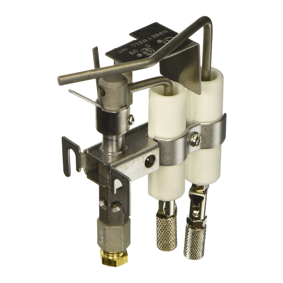
Q179A,B Gas Pilot Burner
Assemblies
GENERAL
Q179A,B Gas Pilot Burner Assemblies use the flame
rectification principle to prove the flame. Q179A,B are used in
conjunction with a suitable electronic flame safeguard control
on industrial or commercial gas and gas pilot ignited oil
burners.
FEATURES
• Q179A is a gas pilot assembly with a flame electrode
(rod) and ignition electrode, making it suitable for
applications requiring an interrupted or intermittent
electrically ignited gas pilot burner.
• Q179A1183 is an "I" port burner with an ignition
electrode (spark) only.
• Q179B has only the flame electrode and is suitable for
use in continuous pilot applications.
• Primary aerated type burner is equipped with stainless
steel fins that provide the proper flame rod area to
ground area ratio for maximum flame signal and flame
stabilization.
• Stainless steel electrode(s) are mounted in ceramic
insulators, which permit electrode adjustment.
General .............................................................................
Features ...........................................................................
Ordering Information ........................................................
Specifications ...................................................................
Installation ........................................................................
Checkout ..........................................................................
PRODUCT DATA
Contents
1
1
2
2
4
5
60-2032-05
Advertisement

Related Manuals for Honeywell Q179A


Summary of Contents for Honeywell Q179A
-
Page 1: Table Of Contents
FEATURES • Q179A is a gas pilot assembly with a flame electrode (rod) and ignition electrode, making it suitable for applications requiring an interrupted or intermittent electrically ignited gas pilot burner. -
Page 2: Ordering Information
If you have additional questions, need further information, or would like to comment on our products or services, please write or phone: 1. Your local Honeywell Automation and Control Products Sales Office (check white pages of your phone directory). 2. Honeywell Customer Care... - Page 3 Q179A,B GAS PILOT BURNER ASSEMBLIES LOCATION OF OPTIONAL FLAME ELECTRODE THERMOCOUPLE GROUND BRACKET IGNITION ELECTRODE (ON Q179A ONLY) ELECTRODE MOUNTING 1-1/2 INSULATORS EARS (38) CLAMP SCREW FOR END INSULATOR MOUNTING 1-5/16 BRACKET (33) 4-7/64 7/32 (6) (104) 7/32 MOUNTING THIS DIMENSION WILL VARY DEPENDING...
-
Page 4: Installation
Q179A,B GAS PILOT BURNER ASSEMBLIES Table 1. Additional Q179A, B Replacement Parts Orifice Flame Rod and Insulator Assembly Tip Style Natural Gas LP Gas Assembly 133448A 395390-25 395390-13 45° I 105064A 395390-25 45° RH 395390-25 45° LH 395390-25 133451A 395390-28 45°... -
Page 5: Checkout
The flame current measurement can be Disconnect power supply to prevent electrical made with a Honeywell W136A Test Meter, which has a 0 to 25 shock and equipment damage. More than one microampere dc scale (see Fig. 4). With the W136A selector disconnect may be involved. - Page 6 Q179A,B GAS PILOT BURNER ASSEMBLIES Pilot Turndown Test If the flame rod is used to prove a pilot flame before the main POSITIVE (+) fuel valve(s) can be opened, perform a pilot turndown test. METER LEAD Follow the procedures in the Instructions for the appropriate...
- Page 7 Q179A,B GAS PILOT BURNER ASSEMBLIES 60-2032-05...
- Page 8 Q179A,B GAS PILOT BURNER ASSEMBLIES Automation and Control Solutions Honeywell International Inc. 1985 Douglas Drive North Golden Valley, MN 55422 Honeywell Limited-Honeywell Limitée 35 Dynamic Drive ® U.S. Registered Trademark Toronto, Ontario M1V 4Z9 © 2011 Honeywell International Inc. 60-2032-05 JPG Rev. 03-11 customer.honeywell.com...