Table of Contents
Advertisement
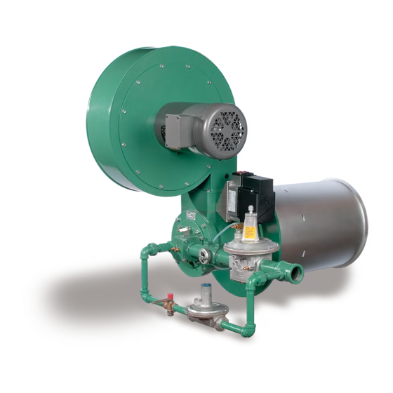
Winnox nozzle-mix, low-emissions air heating
burner
Contents
Safety . . . . . . . . . . . . . . . . . . . . . . . . . . . . . . . . . . . . . . . . 1
Product description. . . . . . . . . . . . . . . . . . . . . . . . . . . . . . 2
Introduction. . . . . . . . . . . . . . . . . . . . . . . . . . . . . . . . . . . . 2
Install flame sensor . . . . . . . . . . . . . . . . . . . . . . . . . . . . . .3
Install burner . . . . . . . . . . . . . . . . . . . . . . . . . . . . . . . . . . .3
Gas piping. . . . . . . . . . . . . . . . . . . . . . . . . . . . . . . . . . . . . 4
Checklist After Installation . . . . . . . . . . . . . . . . . . . . . . . . .5
Adjustment, start and stop . . . . . . . . . . . . . . . . . . . . . . . .6
Maintenance . . . . . . . . . . . . . . . . . . . . . . . . . . . . . . . . . . .9
Spare Parts . . . . . . . . . . . . . . . . . . . . . . . . . . . . . . . . . . .10
Assistance in the event of malfunction. . . . . . . . . . . . . . .10
Technical data . . . . . . . . . . . . . . . . . . . . . . . . . . . . . . . . .10
Disposal . . . . . . . . . . . . . . . . . . . . . . . . . . . . . . . . . . . . .19
oPeRAtInG InstRUCtIons
Version · Edition 12.20 · 32-00057-02 · EN
sAFetY
Disclaimer notice
In accordance with the manufacturer's policy of continual product
improvement, the product presented in this brochure is subject to
change without notice or obligation.
The material in this manual is believed adequate for the intended
use of the product. If the product is used for purposes other than
those specified herein, confirmation of validity and suitability must
be obtained. Honeywell-Eclipse warrants that the product itself does
not infringe upon any United States patents. No further warranty is
expressed or implied.
Liability and Warranty
We have made every effort to make this manual as accurate and
complete as possible. Should you find errors or omissions, please
bring them to our attention so that we may correct them. In this way
we hope to improve our product documentation for the benefit of
our customers. Please send your corrections and comments to our
Marketing Communications Manager.
It must be understood that Honeywell's liability for its product, whether
due to breach of warranty, negligence, strict liability, or otherwise is
limited to the furnishing of replacement parts and Honeywell-Eclipse
will not be liable for any other injury, loss, damage or expenses,
whether direct or consequential, including but not limited to loss of
use, income, or damage to material arising in connection with the
sale, installation, use of, inability to use, or the repair or replacement
of Honeywell-Eclipse's products.
Any operation expressly prohibited in this manual, any adjustment,
or assembly procedures not recommended or authorized in these
instructions shall void the warranty.
Document Conventions
There are several special symbols in this document. You must know
their meaning and importance.
1 2 3 a b c ... = Action
➔ = Instruction/Note
32-00057-02
Advertisement
Table of Contents

Related Manuals for Honeywell Eclipse WX0050


Summary of Contents for Honeywell Eclipse WX0050
-
Page 1: Table Of Contents
Product description......2 It must be understood that Honeywell’s liability for its product, whether due to breach of warranty, negligence, strict liability, or otherwise is Introduction. -
Page 2: Product Description
➔ After making sure everything is present and in good condition, protective clothing when approaching the burner. keep the components in original packages as long as possible. – Honeywell products are designed to minimize the use of Position of Components materials that contain crystalline silica. Examples of these... -
Page 3: Install Flame Sensor
electrical Wiring – Fuel type and supply pressure of the fuel All the electrical wiring must comply with all applicable local codes – Availability of enough fresh, clean combustion air and/or standards such as: – Humidity, altitude and temperature of air –... -
Page 4: Gas Piping
Mounting pattern GAs PIPInG 3 Attach eight mounting bolts to the chamber wall. Position these Burner piping bolts to match the clearance holes ( C) on the burner mounting ➔ The burner is factory assembled and shipped as ordered. flange. note: If you have to realign the pipes, please observe the following! CAUtIon –... -
Page 5: Checklist After Installation
CHeCKLIst AFteR InstALLAtIon To verify proper system installation, do the following: 1 Make sure that there are no leaks in the gas and air lines. 2 Make sure all the components of the flame monitoring control system are properly installed. This includes verifying that all switch- es are installed in correct locations and all wiring, pressure and impulse lines are properly connected. -
Page 6: Adjustment, Start And Stop
step 2 - set low fire air ADJUstMent, stARt AnD stoP 1 Start combustion air blower. In this chapter, you will find instructions on how to adjust, start, and 2 Drive control motor to low fire position. stop the burner system. Become familiar with burner control methods 3 Measure the air differential pressure between tap C and the com- before attempting to make adjustments. - Page 7 step 3 - Ignite the burner Pilot start option Tap E Low fire start Main gas shut-off valve train Pilot gas shut-off Tap E Main gas valve train shut-off valve train Low fire start with pilot start option WARnInG Low fire start –...
- Page 8 step 4 - set low fire gas step 5 - set high fire gas WARnInG – This procedure is written with the assumption the burner has a flame monitoring control system installed and operating. A proper purge cycle must be part of the system and purge timing should not be bypassed.
-
Page 9: Maintenance
step 6 - Verify settings Yearly checklist 1 With burner lit, drive control motor to high fire. 1 Test (leak test) safety shut-off valves for tightness of closure. 2 Wait for the chamber to reach normal operating conditions (e.g. 2 Test air pressure switch settings by checking switch movements chamber temperature, process flows, etc.). -
Page 10: Spare Parts
? the burner goes out when it cycles to high fire. sPARe PARts ! Not enough gas pressure into the ratio regulator. The web app PartDetective for selecting spare parts is available at • Check the start-up settings. Measure the gas pressures and www.adlatus.org. - Page 11 *) All imperial inputs based upon gross calorific values (HHV): one 340 (100) WX0400 atmosphere, 70°F (21°C). All metric inputs based upon net WX0500 570 (170) calorific values (LHV). For lower inputs, contact Honeywell WX0600 550 (160) Eclipse. WX0850 Gas inlet pressure...
- Page 12 General secondary by-pass fuel setting Turndown: 7:1 to 17:1. Burner style: Tap E WX0050–WX0600: upright or inverted, right or left hand piping, Tap B WX0850: upright, right or left hand piping. Fuel types: WX0050: natural gas, WX0100–WX0200: natural gas, propane, Tap D Tap C WX0300–WX0850: natural gas, propane, butane.
- Page 13 Performance Graphs Air ∆p vs. Input Air ΔP vs. Input ∆p measured between Tap C and the chamber with the burner firing Air ∆p vs. Input 1000 2000 3000 4000 5000 Input (kBtu/h) 1000 1250 1500 Input (kW) WX0400 Input (kBtu/h) Air ∆p vs.
- Page 14 – Ratio regulator adjustments – Combustion air temperature Input (kW) CO emission is largely influenced by chamber conditions. WX0100 Contact your Honeywell representative for an estimate of CO emission Emission (On ratio) on your application. Emission (On ratio) - Naturel gas...
- Page 15 Control and operation curve Control and operation curve Typical Ratio Control Typical Ratio Control 1000 2000 3000 4000 5000 6000 1800 2400 1200 3000 3600 Input (kBtu/h) Input (kBtu/h) 1200 1500 1800 1000 Input (kW) Input (kW) WX0500 WX0300 Emission (On ratio) Emission (On ratio) - Naturel gas - Naturel gas...
- Page 16 Emission (On ratio) - Naturel gas - Propane/Butane Input (MMBtu/h) 1000 1500 2000 2500 Input (kW) WX0850 Control and operation curve Typical Ratio Control Input (MMBtu/h) 1000 1500 2000 2500 Input (kW) WX0850 EN-16...
- Page 17 Dimensions Packaged blower (inch) (NPT or Rc fuel Iinlet) UV Scanner Location Bypass fuel regulator 0.4 (10) n x ø0.5 (ø12) Model nPt/ WX0050 ø13.4 ø9.6 ø11.8 11.7 20.4 20.8 WX0100 ø15.2 ø11.8 17.3 ø13.6 12.4 26.4 WX0200 ø18.1 ø14.8 20.3 ø16.5 15.1...
- Page 18 Remote blower (inch) 0.4 (10) (Welded pipe air inlet) (NPT or Rc n x ø0.5 (ø12) pilot fuel Iinlet) Model nPt/Rc WX0050 ø13.4 ø8.9 ø8.7 ø11.8 20.8 20.8 14.4 WX0100 ø15.2 ø11.1 ø10.8 ø13.6 14.4 WX0200 ø18.1 ø14 ø13.8 ø16.5 21.3 21.6 11.2...
-
Page 19: Disposal
DIsPosAL Devices with electronic components: Weee Directive 2012/19/eU – Waste electrical and electronic equipment Directive At the end of the product life (number of operating cy- cles reached), dispose of the packaging and product in a corresponding recycling centre. Do not dispose of the unit with the usual domestic refuse. - Page 20 FoR MoRe InFoRMAtIon The Honeywell Thermal Solutions family of products includes Honeywell Combustion Safety, Eclipse, Exothermics, Hauck, Kromschröder and Maxon. To learn more about our products, visit ThermalSolutions. honeywell.com or contact your Honeywell Sales Engineer. Eclipse Inc. 1665 Elmwood Rd. · Rockford, IL 61103 United States ThermalSolutions.honeywell.com...