Fluke 561 HVACPro User Manual
Fluke infrared thermometer users manual 561 hvacpro
Hide thumbs
Also See for 561 HVACPro:
- User manual ,
- Quick reference quide (6 pages) ,
- Technical data (2 pages)

Related Manuals for Fluke 561 HVACPro


Summary of Contents for Fluke 561 HVACPro
- Page 1 ® 561 HVACPro Infrared Thermometer Users Manual PN 2562924 February 2006 © 2006 Fluke Corporation, All rights reserved. Printed in USA All product names are trademarks of their respective companies.
- Page 2 LIMITED WARRANTY AND LIMITATION OF LIABILITY This Fluke product will be free from defects in material and workmanship for two years from the date of purchase. This warranty does not cover fuses, disposable batteries, or damage from accident, neglect, misuse, alteration, contamination, or abnormal conditions of operation or handling.
-
Page 3: Table Of Contents
Introduction... 1 Contacting Fluke... 1 Safety Information... 2 Features... 3 Display... 4 Buttons and Connector... 5 How the Thermometer Works ... 6 Operating the Thermometer ... 6 Locating a Hot or Cold Spot ... 6 Distance and Spot Size... 6 Field of View ... - Page 4 561 HVACPro Users Manual Measuring Grille, Register, or Diffuser Discharge Temperature ... 15 Verifying Thermostat/Room Sensor Accuracy ... 15 Checking for Blockage in Air-To-Air Evaporators or Condensers... 15 Checking Superheat on Fixed Restrictor or Capillary Tube Equipped Evaporators ... 16 Checking Subcooling on Air-To-Air Systems With Expansion Valve Equipped Evaporators...
-
Page 5: Introduction
Introduction The Fluke Model 561 HVACPro Infrared Thermometer (hereafter, “the Thermometer”) can determine the surface temperature by measuring the amount of infrared energy radiated by the target’s surface or by contact using a thermocouple probe. The Thermometer was designed specifically for use in heating, ventilating, and air conditioning (HVAC) applications. -
Page 6: Safety Information
Thermometer to stabilize before use). Do not leave the Thermometer on or near objects of high temperature. Table 1 and Figure 1 show various symbols and safety markings that are on the Thermometer and in this manual. Symbol Risk of danger. -
Page 7: Features
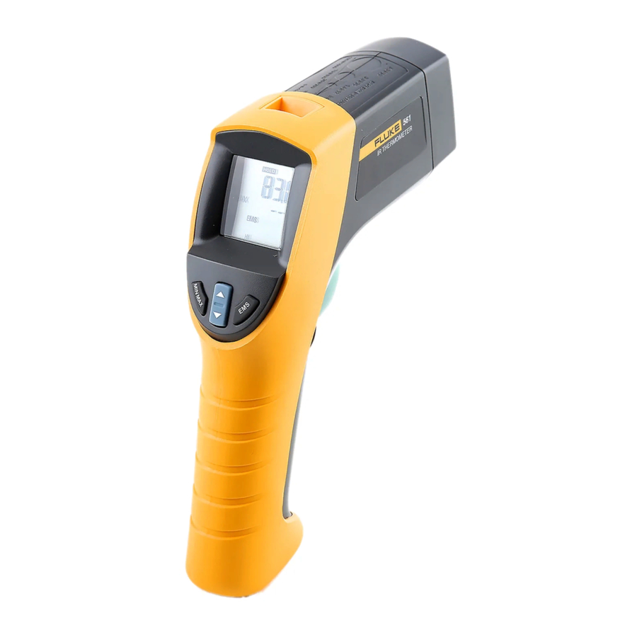
The Thermometer includes: Single-spot Laser Sighting Backlit Display Hard Case Current Temperature Plus MIN, MAX, DIF Temperature Displays Easy Emissivity Selector Type-K Thermocouple, Velcro Pipe Probe Two AA Batteries Thermometer features are shown in Figure 2. Infrared Thermometer Features efh010f.eps... -
Page 8: Display
After the trigger is released, the MIN, MAX, DIF temperatures are held for 7 seconds. When the battery is low, B appears on the display. The last selection (MIN/MAX/DIF) is maintained on the secondary display even after the Thermometer has been turned off, providing the batteries have not failed. -
Page 9: Buttons And Connector
Selects the emissivity setting. You can toggle between LO (0.3), MED (0.7), or HI (0.95) using K-type thermocouple probe used to make contact temperature measurement. Infrared Thermometer Buttons and Connector Figure 3. Thermometer Display Description to toggle between the MIN, MAX, and DIF options. efh01f.eps... -
Page 10: How The Thermometer Works
The spot sizes indicates 90 % encircled energy. The maximum D:S is obtained when the Thermometer is 900 mm (36 in) from the target resulting in a spot size of 75 mm (3 in). See Figure 5. -
Page 11: Field Of View
The Thermometer has three emissivity settings: low (0.3), medium (0.7), and high (0.95). Refer to Table 2. The reference to emissivity settings in the table are suggestions for typical situations. Your particular situation may differ. -
Page 12: Switching Between C And F
Open the battery compartment and locate the switch positioned between the left side of the battery near the Thermometer wall. To toggle between C and F, use a small screwdriver or paper clip to move the switch to the desired position. See Figure 7. -
Page 13: Using The Contact Temperature Probe
To avoid electrical shock or personal injury, do not connect the optional external probe to live electrical circuits. Connect the probe to the input on the top of the Thermometer. The probe temperature and KTC appears in the secondary display. The live infrared temperature continues to show in the primary display. Connect the temperature probe as shown in Figure 8. -
Page 14: Hold
HOLD The display will remain activated for 7 seconds after the trigger is released. HOLD appears in the upper middle of the display. When the trigger is pulled again, the Thermometer will begin measuring in the last function selected. Typical Measurements This section describes a variety of measurements often performed by HVAC technicians. -
Page 15: Testing Insulated Return Ducts
The most likely conditions for condensation formation are low dry bulb temperature and high wet bulb temperature (low temperature, high relative humidity). Use the Fluke 971 to measure the attic/crawlspace relative humidity and determine the dew point temperature. This is the temperature at which condensation will form on the duct wrap. -
Page 16: Testing Contactors (Starters)
HI for insulated connections. Conductors are typically smaller than the Thermometer’s spot size. If the spot size is bigger than the connector, the temperature reading is the average within the spot. Scan the conductor, moving toward direction of electrical connector (quick connect, wire nut, buss connection, or lug). -
Page 17: Testing Bearings
Enable the motor and allow it to reach a steady state operating temperatures. Aim the Thermometer at the surface to be measured. Direct the Thermometer to outside face of belt where it rides in sheave or to the side of sheave at outer edge, whichever is safer or allows easier use of the Thermometer. -
Page 18: Checking Hydronic Radiant Heat Applications
561 HVACPro Users Manual wall you should find parallel isothermal rows indicating the location of heat tubes below the surface. Perpendicular to the outside wall, you should find rising and falling temperatures at equal distances. High temperatures indicate you are scanning a heat tube beneath the floor surface, low falling temperatures indicate a space between the heat tubes. -
Page 19: Measuring Grille, Register, Or Diffuser Discharge Temperature
Measuring Grille, Register, or Diffuser Discharge Temperature Press and then press Aim the Thermometer at the discharge air grille, register, or diffuser. Measure discharge temperature. Release the trigger to freeze the temperature reading for 7 seconds and record the temperature. -
Page 20: Checking Superheat On Fixed Restrictor Or Capillary Tube Equipped Evaporators
Connect low side gauge to suction line. Start system and allow to run at least 10 minutes to reach a steady state condition. Measure the wet bulb temperature in the return using a sling psychrometer or Fluke 971 humidity meter. -
Page 21: Maintenance
Blow off loose particles using clean compressed air. Carefully wipe the surface with a moist cotton swab. The swab may be moistened with water. Cleaning the Housing Use soap and water on a damp sponge or soft cloth. To avoid damaging the Thermometer, do NOT submerge it in water. Troubleshooting Symptom --- (on display) -
Page 22: Specifications
561 HVACPro Users Manual Specifications Infrared Measurement Range ...-40 C to 550 C (-40 F to 1022 F) Spectral Range ...8 to 14 microns Accuracy... 1 % or 1 C (2 F); < 0 C (32 F), Repeatability... 0.5 % of reading or Response Time (95 %)...500 ms...