Table of Contents
Advertisement
Quick Links
Download this manual
See also:
User Manual
Advertisement
Table of Contents

Related Manuals for Fluke DDS Function Generator 271


Summary of Contents for Fluke DDS Function Generator 271
- Page 1 ® Programmable 10 MHz DDS Function Generator Getting Started Manual PN 2423297 January 2005 © 2005 Fluke Corporation, All rights reserved. Printed in USA All product names are trademarks of their respective companies.
- Page 2 Each Fluke product is warranted to be free from defects in material and workmanship under normal use and service. The warranty period is one year and begins on the date of shipment. Parts, product repairs, and services are warranted for 90 days. This warranty extends only to the original buyer or end-user customer of a Fluke authorized reseller, and does not apply to fuses, disposable batteries, or to any product which, in Fluke's opinion, has been misused, altered, neglected, contaminated, or damaged by accident or abnormal conditions of operation or handling.
- Page 3 Safety This function generator is a Safety Class I instrument according to IEC classification and has been designed to meet the re- quirements of EN61010-1 (Safety Requirements for Electrical Equipment for Measurement, Control and Laboratory Use). It is an Installation Category II instrument intended for operation from a normal single phase supply. This instrument has been tested in accordance with EN61010-1 and has been supplied in a safe condition.
- Page 4 60 °C or attempt to recharge. Used batteries should be disposed of by a qualified recycler or hazardous ma- terials handler. Contact your authorized Fluke Service Center for recycling information. Do not wet the instrument when cleaning it and in particular use only a soft dry cloth to clean the LCD win- dow.
- Page 5 Safety (continued) The following symbols are used on the instrument and in this manual: Caution - refer to the accompanying documentation, incorrect operation may damage the instrument. Terminal connected to chassis ground. Mains supply OFF. Mains supply ON. Alternating current. Warning - hazardous voltages may be present.
- Page 7 EMC Compliance This instrument meets the requirements of the EMC Directive 89/336/EEC. Compliance was demonstrated by meeting the test limits of the following standards: Emissions EN61326 (1998) EMC product standard for Electrical Equipment for Measurement, Control and Laboratory Use. Test limits used were: Radiated: Conducted:...
- Page 8 Getting Started Manual EN61000-4-5 (1995) Surge: 0.5 kV (line to line), 1 kV (line to ground) EN61000-4-6 (1996) Conducted RF: 3 V, 80 % AM at 1kHz (ac line only; signal connections <3 m not tested) According to EN61326 the definitions of performance criteria are: Performance criterion A: ‘During test normal performance within the specification limits.’...
-
Page 9: Table Of Contents
Introduction ... 1 Before You Start... 1 Mains Supply Voltage... 1 Externally Applied Voltages ... 2 Controls and Connections ... 3 The Liquid Crystal Display ... 4 Controls ... 4 Function Keys ... 4 FIELD and DIGIT Keys and the Rotary Control ... 5 Numeric, Units and SET Keys ... - Page 10 Getting Started Manual Rear Panel Connectors... 9 Using the Instrument... 11 Starting up... 11 Generating Continuous Signals ... 12 Generating Swept Signals... 16 Generating a Triggered Burst... 18 Special Waveforms ... 19 Saving and Recalling Settings ... 23 Arbitrary Waveforms ... 23 Other Functions and Waveforms ...
-
Page 11: Introduction
Introduction This Getting Started Manual for the model 271 Programmable 10 MHz DDS Function Generator is designed to provide an initial understanding of the way the instrument is operated. The manual is set out in the form of a tutorial, guiding you through a series of basic front panel operations in order to familiarize you with the controls and the modes of operation. -
Page 12: Externally Applied Voltages
Getting Started Manual Externally Applied Voltages Caution - Front Panel Sockets To avoid risk of damage to the instrument: Do not apply external voltages to the MAIN OUT or AUX OUT sockets. Do not apply external voltages exceeding ±10 V to the TRIG IN socket. Caution - Rear Panel Sockets To avoid risk of damage to the instrument: Do not apply external voltages to the... -
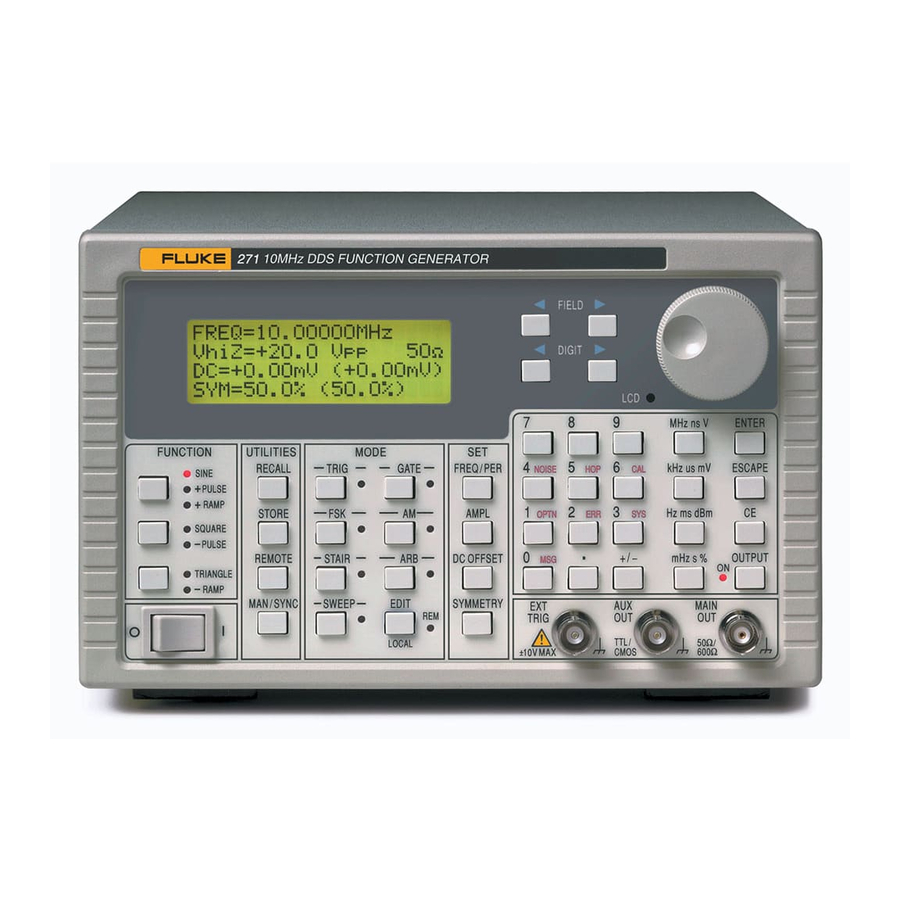
Page 13: Controls And Connections
Getting Started Controls and Connections Controls and Connections shx0001f.gif Figure 1. Model 271 Front Panel... -
Page 14: The Liquid Crystal Display
Getting Started Manual The Liquid Crystal Display The 4-line x 20-character LCD panel is used to display and edit all the parameter values. The paradigm used for selecting fields and editing values is described below. If necessary (because of temperature variations etc.), you can adjust the display contrast using a small screwdriver or trimmer tool inserted in the hole marked LCD. -
Page 15: Field And Digit Keys And The Rotary Control
FIELD and DIGIT Keys and the Rotary Control The FIELD keys move the display cursor between fields. The fields in the display shown in figure 1 above are "FREQ=", "10.00000", "kHz", "VhiZ=" and so on. Each field is one of three types: a parameter name, a parameter value or a unit name. -
Page 16: Numeric, Units And Set Keys
Getting Started Manual Numeric, Units and SET Keys You can use these keys to enter parameter values directly. For example, to set the period to 125 µs, select the first field (FREQ), change it to period (PER) by pressing a DIGIT key, then enter 1, 2, 5, us on the keypad. -
Page 17: Mode Keys
MODE Keys Alternate presses of a MODE key will turn the mode (TRIG, GATE, AM, etc.) on or off, and when the function is on the associated lamp is lit. If you press the EDIT key then press a MODE key you will see the edit menu for that mode. -
Page 18: Front Panel Inputs And Outputs
Getting Started Manual Front Panel Inputs and Outputs MAIN OUT MAIN OUT is the 50 Ω or 600 Ω output from the main generator. It will provide up to 20 V p-p into a high- impedance load or 10 V p-p into a matched 50 Ω... -
Page 19: Rear Panel Connectors
Rear Panel Connectors CLOCK IN/OUT This socket operates both as an input and as an output, depending on the mode in which the instrument is being used. As an input it can be used either to run the instrument from an external master clock or as a synchronization input when slaved to another instrument as the master. -
Page 20: Trig/Sweep Out
Getting Started Manual TRIG/SWEEP OUT The TRIG/SWEEP output socket provides both trigger and marker signals, depending on the instrument's mode of operation. Its primary use is for triggering an oscilloscope or other recording device, but it can also provide z-axis bright-up markers during sweep and frequency-hopping modes. -
Page 21: Using The Instrument
Using the Instrument While familiarizing yourself with the instrument you will find it useful to observe the outputs on an oscilloscope. For most purposes it is sufficient to connect the MAIN OUT front panel socket to the oscilloscope's Y input, and the AUX OUT front panel socket to the oscilloscope's trigger input. -
Page 22: Generating Continuous Signals
Getting Started Manual Generating Continuous Signals Select SINE on the function keys, if it is not already selected. If there is no signal at the oscilloscope input it will almost certainly be because the generator's output is switched off. If the lamp next to the MAIN OUT socket is not lit, press the OUTPUT key. - Page 23 Set the amplitude to +10 dBm You can do this by keying AMPL, 1, 0, dBm. The display will now look like this: PER =80.00000us OUT =+10.0dBm DC=+0.00mV (+0.00mV) SYM=50.0% (50.0%) If you switch the amplitude display back to VhiZ you should see: PER =80.00000us VhiZ=+4.00 Vpp...
- Page 24 Getting Started Manual Effect of the output attenuator The instrument has an output attenuator with fixed steps of 20 dB. The attenuator follows the output stages so any dc offset added to the waveform is subject to the attenuator. With the waveform amplitude set to 4 V p-p the attenuator is switched out;...
- Page 25 Asymmetric waveforms Symmetry adjustments work in much the same way as dc offset adjustments. However, because of the lengthy calculations which the instrument makes following a change to the symmetry setting, you may find it easier to use direct numeric entry rather than the rotary control. Again, the symmetry of the output is displayed in brackets at the right of the programmed value and in certain circumstances the programmed and actual values may...
-
Page 26: Generating Swept Signals
Getting Started Manual instrument's AUX OUT socket in order to see the phase effects more clearly. There are some limitations on using the phase control at frequencies above 30 kHz - chapter 5 of the Users Manual explains these in detail. Generating Swept Signals The instrument has an independently-controlled internal trigger generator which produces a square wave with a... - Page 27 At this point the lamp next to the SWEEP key should be flashing and the display should look like this: MODE=BEG-END LAW=LOG RAMP TIME=0.05 s TRIG SRC=CONTINUOUS MORE->>> All these settings are fine except for the sweep time, which is too short if you are listening to the signal. Change the sweep time to, say, 5 seconds.
-
Page 28: Generating A Triggered Burst
Getting Started Manual Generating a Triggered Burst In this exercise you will use the internal trigger generator to initiate a burst of 500 cycles of a 2 kHz tone twice every second. The period of the internal trigger generator is thus 500 ms. -
Page 29: Special Waveforms
FSK Mode The FSK (frequency shift keying) mode can also be driven from the internal trigger generator. Setting up is very straightforward; the following settings give a continuous waveform which switches between 800 Hz and 1.2 kHz twice every second. The edit menu for the FSK mode includes the basic settings for the trigger generator, so there is no need to visit the trigger generator set-up screen itself. - Page 30 Getting Started Manual set the levels to produce five monochrome stripes from left to right: grey, white, grey, black and grey again. In the instrument the number of horizontal points which make up the complete waveform is 1024, so the horizontal steps must be scaled to the range 0-1023.
- Page 31 step name start (µs) sync pulse back porch 50% grey 12.1 white 22.4 50% grey 32.8 black 43.1 50% grey 53.4 front porch 63.7 These values can now be entered in the staircase set-up screens. Press EDIT then the STAIR key. You should see this screen: VALS=ABS AUTO=YES...
- Page 32 Getting Started Manual The second screen appears: VALS=ABS AUTO=YES STEP=01 ACTIVE LENGTH=0256 LEVEL=+000 Continue entering the pairs of length and level values in the table until the last step (08). This is the final screen in which the length and level have been keyed in, immediately before the final press of the ENTER key: VALS=ABS...
-
Page 33: Saving And Recalling Settings
Saving and Recalling Settings Having done all this work it would be wise to save the settings for future use. You can do this simply by pressing the STORE key, followed by a number in the range 1 to 9 and the ENTER key. -
Page 34: Other Functions And Waveforms
Getting Started Manual arbitrary waveforms 01 to 05. These first five store locations are available for waveforms downloaded from a When you press the ENTER key the output switches to the selected waveform but the display does not change; press ESCAPE to return to the main menu, then press ARB and switch the output on to initiate the signal.