Table of Contents
Advertisement
Quick Links
INSTALLATION & SERVICING
INSTRUCTIONS FOR THE
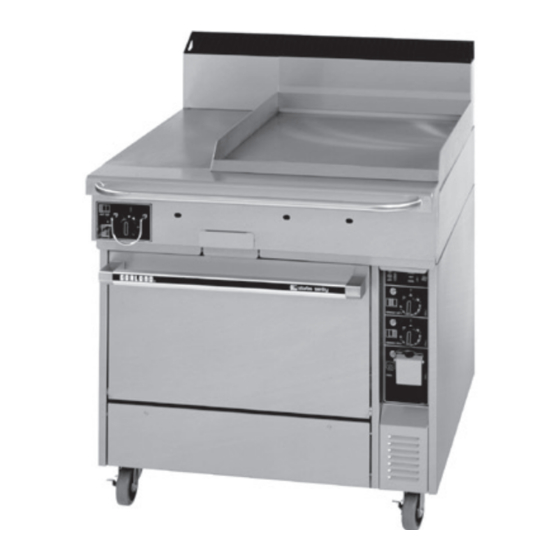
GARLAND® STARFIRE SENTRY
COMBINATION RANGE,
MODEL STW286
FOR YOUR SAFETY
DO NOT STORE OR USE GASOLINE OR OTHER
FLAMMABLE VAPORS OR LIQUIDS IN THE
VICINITY OF THIS OR ANY OTHER APPLIANCE.
KEEP APPLIANCE AREA FREE AND CLEAR
FROM COMBUSTIBLES.
THIS APPLIANCE IS EQUIPPED WITH A THREE-PRONG (GROUNDING) PLUG FOR YOUR PROTECTION
AGAINST SHOCK HAZARD. IT SHOULD BE PLUGGED DIRECTLY INTO A PROPERLY GROUNDED THREE-
PRONG RECEPTACLE. DO NOT CUT OR REMOVE THE GROUNDING PRONG FROM THIS PLUG
DO NOT OBSTRUCT THE FLOW OF COMBUSTION AND VENTILATION AIR TO THIS APPLIANCE.
PLEASE READ ALL SECTIONS OF THIS MANUAL AND RETAIN FOR FUTURE REFERENCE.
THIS PRODUCT HAS BEEN CERTIFIED AS COMMERCIAL COOKING EQUIPMENT AND MUST BE INSTALLED BY
PROFESSIONAL PERSONNEL AS SPECIFIED.
For Your Safety:
Post in a prominent location, instructions to be followed in the event the user smells gas.
This information shall be obtained by consulting your local gas supplier.
Users are cautioned that maintenance and repairs must be performed by a Garland authorized service agent using genuine
Garland replacement parts. Garland will have no obligation with respect to any product that has been improperly installed,
adjusted, operated or not maintained in accordance with national and local codes or installation instructions provided
with the product, or any product that has its serial number defaced, obliterated or removed, or which has been modifi ed
or repaired using unauthorized parts or by unauthorized service agents. For a list of authorized service agents, please refer
to the Garland web site at http://www.garland-group.com. Th e information contained herein, (including design and parts
specifi cations), may be superseded and is subject to change without notice.
Continuous product improvement is a Garland policy, therefore design and specifi cations are subject to change without notice.
GARLAND COMMERCIAL INDUSTRIES
185 East South Street
Freeland, Pennsylvania 18224
Phone: (570) 636-1000
Fax: (570) 636-3903
P151 Rev. 1 (03/05)
P151 Rev. 1 (03/05)
WARNING: ELECTRICAL GROUNDING INSTRUCTIONS
GARLAND COMMERCIAL RANGES,
LTD.
1177 Kamato Road, Mississauga, Ontario L4W 1X4
CANADA
Phone: 905-624-0260
Fax: 905-624-5669
WARNING:
IMPROPER INSTALLATION, ADJUSTMENT,
ALTERATION, SERVICE OR MAINTENANCE CAN
CAUSE PROPERTY DAMAGE, INJURY OR DEATH.
READ THE INSTALLATION, OPERATION AND
MAINTENANCE INSTRUCTIONS THOROUGHLY
BEFORE INSTALLING OR SERVICING
THIS EQUIPMENT.
Enodis UK LTD.
Swallowfi eld Way, Hayes, Middlesex UB3 1DQ ENGLAND
Telephone: 081-561-0433
Fax: 081-848-0041
© 2005 Garland Commercial Industries, Inc.
Page 1
Advertisement
Table of Contents

Related Manuals for Garland STARFIRE SENTRY STW286


Summary of Contents for Garland STARFIRE SENTRY STW286
- Page 1 This information shall be obtained by consulting your local gas supplier. Users are cautioned that maintenance and repairs must be performed by a Garland authorized service agent using genuine Garland replacement parts. Garland will have no obligation with respect to any product that has been improperly installed, adjusted, operated or not maintained in accordance with national and local codes or installation instructions provided with the product, or any product that has its serial number defaced, obliterated or removed, or which has been modifi...
-
Page 2: Important Information
IMPORTANT INFORMATION WARNING: This product contains chemicals known to the State of California to cause cancer and/or birth defects or other reproductive harm. Operation of this product could expose you to carbon monoxide if not adjusted properly. Inhalation of carbon monoxide is known to the State of California to cause birth defects or other reproductive harm. Keep appliance area free and clear from combustibles Page 2 P151 Rev. -
Page 3: Table Of Contents
TABLE OF CONTENTS IMPORTANT INFORMATION ..................2 GENERAL INFORMATION ..................4 Unpacking: ........................4 Serial Plate Location: .......................4 DIMENSIONS & SPECIFICATIONS ................4 INSTALLATION ......................6 General Information .......................6 Clearances ........................6 Appliances Equipped with Casters ..................6 Ventilation & Air Supply ....................7 Mounting Instructions for Backguards ................7 Electrical Connection ......................7 Gas Connection: ......................8 Commissioning: ......................9... -
Page 4: General Information
To access, remove two (2) fasteners securing the panel shut. DIMENSIONS & SPECIFICATIONS EXTERIOR DIMENSIONS Model Height Width Depth STW286 46-3/4" (1187mm) 36" (914mm) 40-1/2 (1029mm) NOTE: Height dimensions specified with casters fitted. Oven Interior Dimensions Entry Clearance Installation Clearances... - Page 5 DIMENSIONS & SPECIFICATIONS continued 1-1/2" GUARD 3-3/4" 11-1/2" (38mm) (95mm) (292mm) 2-5/8" (67mm) 28" 39-3/4" (711mm) (1010mm) 5" (127mm) 2-7/8" (73mm) 12" 24" (305mm) (610mm) 36" (915mm) 45-1/2" (1156mm) 31-3/4" (806mm) 22" (559mm) 5" (127mm) 10' POWER CORD 32-1/2" AT REAR (120V) (825mm) 3/4"...
-
Page 6: Installation
“ON.” combustible surfaces A preset gas pressure regulator is supplied with GARLAND Restaurant Series Equipment. It may MINIMUM CLEARANCES STW286 be necessary to adjust the regulator to deliver fuel at LOCATION CLEARANCE the pressure shown on the rating plate. -
Page 7: Ventilation & Air Supply
INSTALLATION continued B. The front casters on the appliance are equipped F. If the appliance is banked with others that have with brakes to limit the movement of the appliance backguards installed, replace the flat head bolts without placing any strain on the connector or removed in Step B so that the upright of the quick disconnect device or its associated piping. -
Page 8: Gas Connection
INSTALLATION continued Gas Connection: an emergency or routine servicing. After installation, the complete pipe work must be checked for soundness. The gas pipe connection is made at the rear right hand side of the equipment. The size of the pipe work supplying TABLE A. -
Page 9: Commissioning
INSTALLATION continued Commissioning: 3. With a flat screwdriver, turn the adjuster on the body of the tap clockwise to reduce the pressure or The whole of the gas installation, including the meter, anti-clockwise to increase pressure. Set the pressure should be inspected, purged and tested for leakage in to correspond with table D. -
Page 10: Maintenance & Cleaning
MAINTENANCE & CLEANING Regular servicing by a competent person is recommended 5. Remove the injector support and slide the burner to ensure the continued safe and efficient performance and burner pan forwards out of the combustion of the appliance. chamber. WARNING: Turn off... -
Page 11: Griddle
MAINTENANCE & CLEANING continued 3. Check the temperature reading just when the sensing bulb of the thermostat. (see the following control cycles “OFF” as indicated by cycling pilot diagram for how to find the location directly above lamp. If the temperature does not read within 15°F the thermostat sensing bulb) The reading should be of the dial setting, recalibrate as follows: between 285°F and 315°F. -
Page 12: Conversion Instructions
Injector fittings ( One required for each main burner & one required for each pilot) b. Regulator, (one per unit ) If any of the required parts are missing, contact your Garland dealer before attempting to carry out the conversion. Page 12 P151 Rev. 1 (03/05) -
Page 13: Fault Finding
FAULT FINDING PROBLEM POSSIBLE CAUSES SOLUTION No power to oven. Check power supply. Defective Cook/Cool Down switch Replace switch. Cook/Cool Down switch set to “Cook” position. Light off. Motor not working. Faulty wiring. Check condition of all wires & connections Defective door switch. -
Page 14: Replacement Of Parts
REPLACEMENT OF PARTS WARNING: Turn off the gas supply to the appliance Control Panel Rocker Switches at the service cock and the 1. Remove the fastener securing the control electrical mains before commencing any servicing compartment access panel. work. 2. Slide out the control drawer to access the switch. IMPORTANT: Test for gas soundness on completion 3. -
Page 15: Gas Control Valve
REPLACEMENT OF PARTS continued Gas Control Valve 4. Using an allen head wrench loosen the screw securing the blower wheel to the motor shaft and 1. Remove the fastener securing the control remove the wheel. compartment access panel. 5. Remove the four (4) screws securing the motor 2. -
Page 16: Wiring Diagrams
WIRING DIAGRAMS Page 16 P151 Rev. 1 (03/05) - Page 17 WIRING DIAGRAMS 24V D SPARK P151 Rev. 1 (03/05) Page 17...
- Page 18 NOTES Page 18 P151 Rev. 1 (03/05)
- Page 19 NOTES P151 Rev. 1 (03/05) Page 19...