
Related Manuals for PRESONUS FP10


Summary of Contents for PRESONUS FP10
- Page 1 FP10 24-bit/96k Recording Interface w/ Eight Microphone Preamplifiers User’s Manual Version 1.1 © 2007, PreSonus Audio Electronics, Inc. All Rights Reserved.
- Page 2 PRESONUS LIMITED WARRANTY PreSonus Audio Electronics Inc. warrants this product to be free of defects in material and workmanship for a period of one year from the date of original retail purchase. This warranty is enforceable only by the original retail purchaser.
-
Page 3: Table Of Contents
2.3.3 USB and other types ........................16 2.4 Using The Preamp Output and Line Input as an Insert ................17 3 CONTROLS & CONNECTIONS 3.1 FP10 Control Panel ..........................17 3.1.1 FP10 Advanced Settings ......................17 3.1.2 FP10 Hardware Settings ......................18 3.2 Front Panel Layout .......................... -
Page 5: Overview
We suggest that you use this manual to familiarize yourself with the features, applications and correct connection procedure for your FP10 before trying to connect it to your computer. This will hopefully alleviate any unforeseen issues that you may encounter during installation and set up. -
Page 6: Features
S/PDIF and MIDI I/O, rock solid drivers, expandability, as well as a plethora of music recording and production software. The FP10 includes PreSonus ProPak Software Suite with Cubase LE and over 2 GB of plug-ins, drum loops and samples – giving you everything you need for professional music recording and production. Need more inputs? Three FP10’s can be daisy-chained for up to 24 simultaneous microphone inputs in just three rack spaces! -
Page 7: What Is In The Box
OVERVIEW 1.3 WHAT IS IN THE BOX Your FP10 package contains the following: • FP10 Recording Interface • 2 meter 6-pin to 6-pin FireWire cable • FP10 Power Supply • Software installation discs: PreSonus FP10 Installation Drivers Cubase LE 4 ProPak •... -
Page 8: System Requirements
OVERVIEW 1.4 SYSTEM REQUIREMENTS Below are the minimum computer system requirements for your FP10. Macintosh • OS: Mac OS X 10.3.5 or later • Computer: Apple Macintosh series with FireWire 400 port • CPU/Clock: PowerPC G4/800MHz or higher (G4/Dual 1 GHz recommended) •... -
Page 9: Operation
2.1 QUICK START UP 2.1.1 Installation in Microsoft Windows The FP10 installer will take you through each step of the installation process. Please read each message carefully – ensuring especially you do not connect your FP10 early. 1) Insert the FP10 Driver Installation CD included with your FP10 into your computer and follow its prompts. - Page 10 Windows XP only Click [Continue Anyway] to continue. Click [STOP Installation] to cancel and setup. 4) Connect your FP10 to your computer using the included FireWire cable and turn it on. Click [Next >] to continue. Multiple FP10’s only...
- Page 11 Click [Continue Anyway] to continue the FP10 Installation. Click [STOP Installation] to cancel and exit setup. 5) The sync light on your FP10 should be solid blue to indicate it has been successfully installed. Click [Finish] to complete setup. 9 | PreSonus 2007...
-
Page 12: Installation In Mac Os X
OPERATION 2.1.2 Installation in Mac OS X The FP10 audio drivers are included in the Core Audio of Mac OS X version 10.3.5 and later. 1) Connect your FP10 to your computer’s FireWire port and turn it on. The sync light should flash a few times. -
Page 13: Cubase Le - Device Setup
2.1.3 Cubase LE 4 – Device Setup Once you have installed the FP10 drivers and connected your FP10, you can use the Cubase LE Music Creation and Production System software included with your FP10 to begin recording, mixing and producing your music. - Page 14 OPERATION ASIO Driver 3) Select ‘FP10 ASIO Driver’ from the dropdown list. 4) Click ‘Switch’ to begin using the FP10 Driver. For more help on using Cubase LE 4, read the Getting Started Operation Manual help documents located in Help > Documentation.
-
Page 15: Cubase Le - Creating A Project
MIDI tracks to record and edit on. Follow these simple steps to begin recording your first audio in Cubase LE: 1) Plug an XLR microphone or instrument into FP10 channel one and turn on 48V phantom power if needed for your microphone (typically only for condenser microphones.) - Page 16 9) Turn up the gain control knob on the front panel of the FP10 for channel 1 while speaking/singing into the microphone or while playing your instrument. You should see the input meter in Cubase LE react to the input.
-
Page 17: Sample Hookup Diagram
2.2 SAMPLE HOOK UP DIAGRAM With the FP10, you can simultaneously record and play back up to 10 channels. Since it is loaded with eight preamplifiers, you can plug in eight microphones to the FP10 along with S/PDIF digital input to record a full band. -
Page 18: Microphones
OPERATION 2.3 MICROPHONES The FP10 works great with all types of microphones including dynamic, ribbon and condenser microphones. 2.3.1 Condenser Condenser microphones tend to generate a high-quality audio signal and are one of the most popular mic choices for today’s studio recording applications. Because of their design technology, condenser microphones require a power source, which can be provided from a small battery, external power supply or from phantom power. -
Page 19: Using The Preamp Output And Line Input As An Insert
EQ’s, de-essers, etc. Simply connect the Preamp Output jack to the line input of your external processor. Then connect the line output of the external processor to the Line Input 1 or 2 of the FP10. The input signal from channel 1 and/or 2 is now routed out of the FP10 into the external processor and back into the FP10. -
Page 20: Controls & Connections
CONTROLS AND CONNECTIONS 3.1 FP10 CONTROL PANEL Once you have successfully installed your FP10, the FP10 Control Panel will be available from your system tray (typically at the bottom right corner of your screen near the clock). Right-click the FP10 icon to access the FP10 Advanced Settings menu. Double-click on the FP10 icon to open the FP10 Hardware Control Panel. - Page 21 ASIO’ after renaming your FP10. Mac OS X Only Sync Source is the only parameter in the FP10 Control application. The FP10 Sample Rate can be changed either through Audio MIDI Setup or in your recording software’s hardware or project preferences.
-
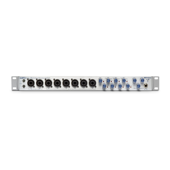
Page 22: Front Panel Layout
Neutrik Combo connector. This revolutionary style connector lets you use either ¼” phone or XLR connectors in the same female input. The first two channels of the FP10 are ¼” instrument and microphone XLR inputs. The line level inputs for these two channels are on the back panel of the FP10. -
Page 23: Controls And Connections
Plugging a line level source into the instrument inputs on the front of the FP10 not only risks damage to these inputs but also results in a very loud and often distorted audio signal. - Page 24 CONTROLS AND CONNECTIONS • Main. The Main knob controls the output level for the Main CR Outputs 1 & 2 on the back of the FP10 with a range of -80db to +10dB. • Mixer. The Mixer knob is like a balance control. It balances the Headphone, Main and Cue outputs between a mono analogue mix of Inputs 1-8 and computer playback outputs 1 and 2.
-
Page 25: Back Panel Layout
• Power Switch. Push the top part of the switch to turn your FP10 on ( | ). Push the bottom part of the switch to turn your FP10 off ( O ). - Page 26 Mic/Instrument input on the front of the FP10. (I.E., if a cable is plugged into channel one line input on the rear of the FP10, the channel one Mic/Instrument input will be inactive until the cable is removed from line input one.) •...
-
Page 27: Technical Information
Pops and Clicks The light on the front right panel of the FP10 is a clock (sync) indicator. It lets you know if your unit is receiving word clock correctly. Word clock is the manner by which digital devices sync frame rates. Proper word clock sync prevents digital devices from having pops, clicks or distortion in the audio signal due to mismatched digital audio transmission. - Page 28 2. Make sure the microphone does not require phantom power. If it does, press the 48V button. 3. Make sure nothing is plugged into the line input on the rear of the FP10. The line inputs on channels 1 and 2 take precedence over the combo input on the front of the unit on channels 1 and 2.
-
Page 29: Specifications
TECHNICAL INFORMATION 4.2 SPECIFICATIONS Microphone Preamp Type ..........................XLR Female Balanced Frequency Response (±0.5 dB) ....................20 Hz to 50 kHz Frequency Response (±3.0 dB) ..................... 20 Hz to 150 kHz Input Impedance (Balanced) ........................ 1600 Ω THD+N (unwtd, 1 kHz @ +4 dBu Output, Unity Gain) ..............< 0.003% EIN (unwtd, 55dB Gain, 150 Ω... - Page 30 TECHNICAL INFORMATION Line Outputs (including Preamp Output, Main CR Output, Cue Mix Line Out) Type ............................ ¼” TRS Balanced Output Impedance ............................ 51 Ω Headphone Output Type ..........................¼” TRS Active Stereo Maximum Output ..................... 150 mW/Ch @ 60 Ω Load Frequency Response (±1.0 dB) ....................