Powermatic 201 Operating Instructions And Parts Manual
22-inch planer
Hide thumbs
Also See for 201:
- Features and benefits (4 pages) ,
- Instruction manual and parts list (40 pages)
Table of Contents
Advertisement
This .pdf document is bookmarked
Operating Instructions and Parts Manual
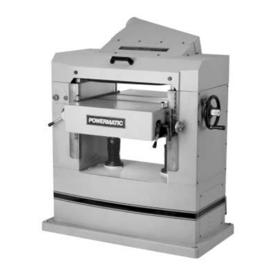
22-inch Planer
Models 201 and 201HH
WALTER MEIER (Manufacturing) Inc.
427 New Sanford Road
LaVergne, Tennessee 37086
Part No. M-0460224
Ph.: 800-274-6848
Revision G2 11/2011
www.waltermeier.com
Copyright © 2011 Walter Meier (Manufacturing) Inc.
Advertisement
Table of Contents
Troubleshooting

Related Manuals for Powermatic 201


Summary of Contents for Powermatic 201
- Page 1 This .pdf document is bookmarked Operating Instructions and Parts Manual 22-inch Planer Models 201 and 201HH WALTER MEIER (Manufacturing) Inc. 427 New Sanford Road LaVergne, Tennessee 37086 Part No. M-0460224 Ph.: 800-274-6848 Revision G2 11/2011 www.waltermeier.com Copyright © 2011 Walter Meier (Manufacturing) Inc.
-
Page 2: Warranty And Service
This warranty covers only the initial purchaser of the product. WHAT IS THE PERIOD OF COVERAGE? The general POWERMATIC warranty lasts for the ti m e period specified in the product literature of each product. WHAT IS NOT COVERED? The Five Year Warranty does not cover products used for commercial, industrial or educational purposes. Products with a Five Year Warranty that are used for commercial, industrial or education purposes revert to a One Year Warranty. -
Page 3: Table Of Contents
Table of Contents Warranty and Service..........................2 Table of Contents ..........................3 Warning .............................4 Introduction ............................6 Specifications .............................6 Receiving ............................7 Installation............................7 Installing Dust Hood ........................8 Grounding Instructions ........................8 Inspection ............................9 Adjustments ............................9 Depth of Cut............................9 Feed Rate Adjustment ........................9 Belt Tension ............................9 Opening Hood .......................... -
Page 4: Warning
Warning 1. Read and understand the entire owner’s manual before attempting assembly or operation. 2. Read and understand the warnings posted on the machine and in this manual. Failure to comply with all of these warnings may cause serious injury. 3. - Page 5 19. Make your workshop child proof with padlocks, master switches or by removing starter keys. 20. Give your work undivided attention. Looking around, carrying on a conversation and “horse-play” are careless acts that can result in serious injury. 21. Maintain a balanced stance at all times so that you do not fall or lean against moving parts. Do not overreach or use excessive force to perform any machine operation.
-
Page 6: Introduction
Introduction This manual is provided by Walter Meier (Manufacturing) Inc., covering the safe operation and maintenance procedures for a Powermatic Model 201 and 201HH Planer. This manual contains instructions on installation, safety precautions, general operating procedures, maintenance instructions and parts breakdown. This machine has been designed and constructed to provide years of trouble free operation if used in accordance with instructions set forth in this manual. -
Page 7: Receiving
1 dust chute w/ fasteners 4 screws w/ hex nuts (for leveling feet) 4 leveling feet 1 knife-setting gauge (201 only) 2 star point screwdrivers (201HH only) 1 set of 10 knife inserts (201HH only) 10 knife insert screws (201HH only) -
Page 8: Installing Dust Hood
Installing Dust Hood Mount the dust hood with the eight M6 x 10mm hex screws, eight spring washers, and eight flat washers. See Figure 3. It is strongly recommended that a dust collection system be connected to the 5” port on the planer’s dust hood. -
Page 9: Inspection
Feed Rate Adjustment The Model 201 is equipped with selectable feed speed rollers that feed stock at 20 and 30 feet per minute. To adjust speed, turn lever shown in Figure 5, while the planer is running. -
Page 10: Opening Hood
4. Replace the springs and gib into the slot, then insert new knife and lightly snug the Figure 8 – Model 201 only eight gib screws. 5. Place the knife-setting gauge on the cutterhead as shown in Figure 9, with the... -
Page 11: Replacing Or Rotating Knife Inserts (Helical Cutterhead Only)
7. Rotate the cutterhead using the belt or pulley, and repeat steps 2 through 6 for each of the remaining three knives. 8. When all four knives have been installed and made snug, begin the tightening process. NOTE: All knives and gibs should be in place before tightening. -
Page 12: The Planer's Feed System
The Planer’s Feed System (Refer to Figure 11) 1. Anti-kickback fingers 2. Infeed roller 3. Chipbreaker 4. Cutterhead 5. Pressure bar 6. Outfeed roller Anti-Kickback Fingers Anti-kickback fingers help prevent stock from being thrown from the machine. These fingers operate by gravity and should be inspected for pitch or gum buildup before each day's use. -
Page 13: Chipbreaker
6. If it is not 1/16” below the knife, correct by loosening the hex nut and turning the adjustment screw (A, Figure 14) with a hex wrench. 7. Move the gauge to the extreme right end of the infeed roller and check. Make similar adjustments if needed. -
Page 14: Outfeed Roller
Outfeed Roller The outfeed roller is of smooth, one-piece construction to help avoid marring the finished surface of the material being cut. It is spring tensioned, and its function is to continue to feed the material through the machine after it leaves the infeed roller. -
Page 15: Table Adjustments
5. If the gauge reading is greater or less than zero, reach beneath the table with a wrenc h and loosen the hex nut (C, Figure 17) whic h is above the cam (D, Figure 17) near the end of the roller that needs adjusting. Rotate the hex cap screw (E, Figure 17) until the gauge reads zero. -
Page 16: Operating Controls
Operating Controls The stop button is a mushroom style button which is convenient for “emergency” shutdowns. After being pushed, the stop button remains engaged. To re-start the planer, twist the stop button clockwise until it pops back out. Test Cutting and Troubleshooting Using a piece of semi-finished stock, set up for a 1/16"... - Page 17 Snipe Some amount of snipe may be inevitable with many planer operations, but proper planer adjustments can so minimize snipe as to make it negligible. If noticeable snipes appear on each end of the Figure 22 material, as shown in Figure 22, a table roller is (snipe) too high causing a slight lift of the material as it passes through the machine.
-
Page 18: Maintenance
TIP: If a foreign object nicks the knives on the straight cutterhead (Model 201), instead of throwing them away or trying to grind out the deep nick, simply stagger the knives in the head, moving one knife no more than 1/4” to the right and another knife no more than 1/4”... -
Page 19: Troubleshooting: Planer Operating Problems
Troubleshooting: Planer Operating Problems Trouble Probable Cause Remedy Table rollers not set properly. Adjust table rollers to proper height. Support long boards with a roller Inadequate support of long boards. stand. Uneven feed roller pressure front to Adjust feed roller tension. Snipe. -
Page 20: Troubleshooting: Mechanical And Electrical Problems
Troubleshooting: Mechanical and Electrical Problems Trouble Probable Cause Remedy Make sure knives are set correctly Knives not set correctly. Uneven depth of cut and securely in cutterhead. side to side. Adjust table parallel to cutterhead. Planer table not parallel to cutterhead. See page 15. -
Page 21: Replacement Parts
Trouble Probable Cause Remedy Machine will not Starter or motor failure (how to Examine motor starter for burned or start/restart or distinguish). failed components. If damage is repeatedly trips found, replace motor starter. circuit breaker or If you have access to a voltmeter, you blows fuses. -
Page 22: Parts List: Base Assembly
Parts List: Base Assembly Index No. Part No. Description Size 1 ....6012068 ....Rubber Boot ..................2 2 ....6012069 ....Lead Screw ..................1 3 ....6293370 ....Key ..............5 x 5 x 10 ....2 4 ....6012070 ....Screw w/ Washer......M4x0.7Px8Lg / 4mmx10x0.8T ..4 5 .... - Page 23 21 .... 6292745 ....Key ..............5 x 5 x 16 ....2 22 .... 6012085 ....Chain ...............#40 x 79pcs....1 23 .... 6012086 ....Bevel Gear ..................1 24 .... 6012087 ....Screw ..............M5 x 0.8P x 10Lg..4 25 .... 6012088 ....Strain Relief Clip ..........ACC-3......4 26 ....
-
Page 24: Gearbox Assembly
Gearbox Assembly... -
Page 25: Parts List: Gearbox Assembly
Parts List: Gearbox Assembly Index No. Part No. Description Size ....201-100....Gearbox Assembly ................1 1 ....6012034 ....Gearbox Body ..................1 2 ....6012035 ....Ball Bearing............6201-2NSE ....6 3 ....6012036 ....S-Ring .............STW-16 ..... 2 4 ....6012037 ....Gear ....................2 5 .... -
Page 26: Column Assembly
Column Assembly... -
Page 27: Parts List: Column Assembly
Parts List: Column Assembly Index No. Part No. Description Size 1 ....6012193 ....Lifting Eye ............M20 x 2.5P x 30Lg ..2 2 ....6012194 ....Left Column..................1 3 ....6012195 ....Pin ..................... 4 4 ....6012079 ....Hex Nut............M10 x 1.5P ....1 5 .... -
Page 28: Table Assembly
Table Assembly... -
Page 29: Parts List: Table Assembly
Parts List: Table Assembly Index No. Part No. Description Size 1 ....6012233 ....Bracket ....................4 2 ....BB-6203ZZ ....Ball Bearing............6203-ZZ ..... 4 3 ....6012234 ....Roller Assembly.................. 2 4 ....6012079 ....Hex Nut............M10 x 1.5P ....4 5 ....6012235 ....Hex Screw ............M10 x 1.5P x 30Lg ..4 6 .... -
Page 30: Parts List: Top Cover Assembly
Parts List: Top Cover Assembly Index No. Part No. Description Size 1 ....6012181 ....Dust Hood ..................1 2 ....6012091 ....Screw ..............M6 x 1.0P x 10Lg..18 3 ....6012182 ....Spring Washer..........6.1mm x 12.3 ... 18 4 ....6012183 ....Flat Washer............6.6mm x 13 x 1T ..18 5 .... -
Page 31: Cutterhead Assembly
Cutterhead Assembly... -
Page 32: Parts List: Cutterhead Assembly
Parts List: Cutterhead Assembly Index No. Part No. Description Size 1 ....6012131 ....Socket Head Cap Screw ........M10 x 1.5P x 75Lg ..2 2 ....6012080 ....Flat Washer............10mm x 25 x 3T ..10 3 ....6012132 ....Spring ....................2 4 .... - Page 33 77 .... JJ6HH-113 ....Star Point Screwdriver (not shown)** ........... 2 Index # 30, 35, 36, 57, 58, 70, 71 are used only with the straight cutterhead on Model 201. ** Index # 74, 75, 76, 77 are used only with the helical cutterhead on Model 201HH.
-
Page 34: Electrical Connections - 1 Phase, 230 Volt
Electrical Connections – 1 Phase, 230 Volt... -
Page 35: Electrical Connections - 3 Phase, 230 Volt
Electrical Connections – 3 Phase, 230 Volt... -
Page 36: Electrical Connections - 3 Phase, 460 Volt
Electrical Connections – 3 Phase, 460 Volt...