Powermatic 201 Instruction Manual And Parts List
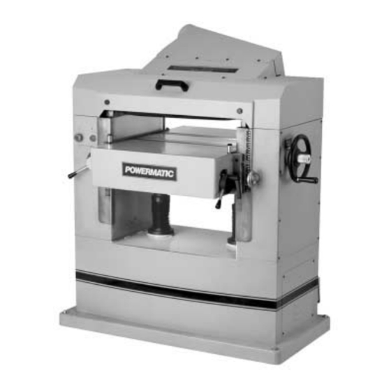
22" planer
Hide thumbs
Also See for 201:
- Features and benefits (4 pages) ,
- Operating instructions and parts manual (36 pages)

Related Manuals for Powermatic 201


Summary of Contents for Powermatic 201
- Page 1 22" PLANER Model 201 Instruction Manual & Parts List M-0460224 (800) 274-6848 www.powermatic.com...
- Page 2 This manual has been prepared for the owner and operators of a Powermatic Model 201 Planer. Its purpose, aside from machine operation, is to promote safety through the use of accepted correct operating and maintenance procedures. Completely read the safety and maintenance instructions before operating or servicing the machine.
-
Page 3: Table Of Contents
Depth of Cut ...9 Feed Rate Adjustment ...9 Belt Tension ...9 Opening Hood ... 10 Knife Installation & Adjustment ... 10 The Feed System of Your Planer... 11 Anti-Kickback Fingers... 11 Infeed Roll ... 11 Chipbreaker... 12 Pressure Bar... 12 Outfeed Roll ... -
Page 4: Safety Rules
Make certain the work area is well lighted and that a proper exhaust system is used to minimize dust. Powermatic recommends the use of anti-skid floor strips on the floor area where the operator normally stands and that each machine’s work area be marked off. - Page 5 Misuse. Do not use this Powermatic planer for other than its intended use. If used for other purposes, Powermatic disclaims any real or implied warranty and holds itself harmless for any injury or damage which may result from that use.
-
Page 6: Safety: Decals
Familiarize yourself with the following safety notices used in this manual: CAUTION: (This means that if precautions are not heeded, it may result in minor or moderate injury and/or possible machine damage) WARNING: (This means that if precautions are not heeded, it could result in serious injury or possibly even death). -
Page 7: Specifications
Motor... 7.5 HP, 3 Ph, 230V or 7.5 HP, 3 Ph, 460V or 7.5 HP, 1 Ph, 230V Shipping weight ... 1,197 lbs. NOTE: The above specifications were current at the time this manual was published, but because of our policy of continuous improvement, Powermatic reserves the right to change specifications without notice and without incurring obligations. -
Page 8: Receiving
Remove the screws holding the base of the machine to the skid. Use the lifting eyes on front and back of the planer for hoisting it off the skid. See Figure 1. Make sure the hex nuts are tightened before lifting. The eyes should be removed once the planer is situated. -
Page 9: Inspection
The pointer (D) can be adjusted if the scale should ever need recalibrating. FEED RATE ADJUSTMENT The Model 201 is equipped with selectable feed speed rolls that feed stock at 20 and 30 feet per minute. To adjust speed, turn lever shown in Figure 4. -
Page 10: Opening Hood
CAUTION: Use care when placing hands near knives as they are extremely sharp and can cause severe cuts. Installing knives on a planer is an exacting process. If the knives are not to be jointed and ground, end-to-end and knife-to-knife relationship must be held within .001"... -
Page 11: The Feed System Of Your Planer
The infeed roll is under spring tension and this tension must be sufficient to feed the stock uniformly through the planer without slipping but should not be so tight that it causes damage to the boards. The tension should be equal at both ends of... -
Page 12: Chipbreaker
To adjust the infeed roll: Place a bed and feed roll gauge (accessory #2230002) under a knife in the cutterhead and raise the table until the gauge contacts the knife at the apex of its curve. See Figure 10. NOTE: If a bed and feed roll gauge is not available, use a finished block of wood with notches cut out for the table rolls, and a feeler gauge. -
Page 13: Outfeed Roll
Figure 13. TABLE ROLLS The Model 201 Planer has two table rolls which help reduce friction of the stock on the table as it feeds through the machine. It is not possible to give exact height setting of the table rolls because each type of wood behaves differently. -
Page 14: Table Adjustments
Re-tighten the hex nuts (C-Fig. 15) on both ends of the table roll. Repeat for other roll. TABLE ADJUSTMENTS The planer table is raised and lowered by twin screws supported on bearings, and is guided by machined surfaces on the side panels. The fit-up to prevent the table from rocking is controlled by two gibs in front. - Page 15 About 90 percent of the time, the pressure bar is too low. As the sharp edge of the planer knives wear, you must compensate for this wear by raising the pressure bar an equal amount on each side.
- Page 16 If they are, then the table itself must be adjusted. See “Table Adjustment” above. TWISTING: If material twists while feeding through the planer, either the table rolls, pressure bar, or outfeed roll may be out of level. Place the bed and feed roll gauge (or a gauge...
-
Page 17: Maintenance
MAINTENANCE Periodic or regular inspections are required to ensure that the machine is in proper adjustment, that all screws are tight, that belts are in good condition, that dust has not accumulated in the electrical enclosures, and that there are no loose or worn electrical connections. Buildup of sawdust and other debris can cause your machine to plane inaccurately. - Page 18 TROUBLE-SHOOTING: OPERATING PROBLEMS (201 Planer) PROBLEM POSSIBLE CAUSE Snipe 1. Table rollers not set properly. 2. Inadequate support of long boards. (NOTE: Snipe can be minimized but not 3. Uneven feed roll pressure front to back. eliminated.) 4 Dull knives 5.
-
Page 19: Trouble-Shooting
See items 9 & 10 below. 4. Verify that planer is on a circuit of correct size. If circuit size is correct, there is probably a loose electrical lead. Check amp setting on motor starter. - Page 20 Machine will not start/ 7. Motor starter failure. restart or repeatedly trips circuit breaker or blows fuses 8. Motor failure. 9. Miswiring of the unit. Therefore, 10. On/off switch failure. 7. (continued) If voltage between starter and motor is incorrect, you have a starter problem.
- Page 21 PARTS LIST: Gearbox Assembly (Model 201 Planer) Part No. Description 6012034 Gearbox Body...1 6012035 Ball Bearing, 6201-2NSE ...6 6012036 S-Ring, STW-16 ...2 6012037 Gear ...2 6012038 Ball Bearing, 6204-2NSE ...2 6012039 Oil Seal, TC24 x 40 x 8...1 6012040 Shaft...1 6293370 Key, 5 x 5 x 10...4...
-
Page 22: Gearbox Assembly
Gearbox Assembly (Model 201 Planer) -
Page 23: Cutterhead Assembly
PARTS LIST: Cutterhead Assembly (Model 201 Planer) Part No. Description 6012131 Socket Head Cap Screw, M10 x 1.5P x 75Lg ... 2 6012080 Flat Washer, 10mm x 25 x 3T ... 10 6012132 Spring ... 2 6012133 Socket Head Cap Screw, M10 x 1.5P x 50Lg ... 2 6012079 Hex Nut, M10 x 1.5P ... - Page 24 Part No. Description 6012179 Knife (set of 4) ...1 6012180 Gib Screw... 32 6012273 Spring...2 6012274 Chain #40 x 72 pcs (gearbox to outfeed roll)...1 6012275 Shaft...1 6012276 Idle Sprocket...1 6012277 Bracket ...1 6012278 Shaft...1 6012279 Check Nut M8 x 1.25P ...1 6012083 Flat Washer, 8.5mm x 19 x 2T...1 6012280...
-
Page 25: Cutterhead Assembly
Cutterhead Assembly (Model 201 Planer) -
Page 26: Top Cover Assembly
PARTS LIST: Top Cover Assembly (Model 201 Planer) Part No. Description 6012181 Dust Hood...1 6012091 Screw, M6 x 1.0P x 10Lg ... 18 6012182 Spring Washer, 6.1mm x 12.3 ... 18 6012183 Flat Washer, 6.6mm x 13 x 1T... 18 6012184 Upper Cover ...1... -
Page 27: Top Cover Assembly
Top Cover Assembly (Model 201 Planer) -
Page 28: Column Assembly
PARTS LIST: Column Assembly (Model 201 Planer) Part No. Description 6012193 Lifting Eye, M20 x 2.5P x 30Lg ...2 6012194 Left Column ...1 6012195 Pin...4 6012079 Hex Nut, M10 x 1.5P...1 6012080 Flat Washer, 10mm x 25 x 3T... 17 6012066 Socket Head Cap Screw, M8 x 1.25P x 25Lg...6... -
Page 29: Column Assembly
Column Assembly (Model 201 Planer) -
Page 30: Table Assembly
PARTS LIST: Table Assembly (Model 201 Planer) Part No. Description 6012233 Bracket...4 BB-6203ZZ Ball Bearing, 6203-ZZ...4 6012234 Roller Assembly ...2 6012079 Hex Nut, M10 x 1.5P ...4 6012235 Hex Screw, M10 x 1.5P x 30Lg...4 6012236 Hex Screw, M8 x 1.25P x 16Lg...2 6012237 Hex Screw, M6 x 1.0P x 16Lg ...2... -
Page 31: Table Assembly
Table Assembly (Model 201 Planer) -
Page 32: Base Assembly
PARTS LIST: Base Assembly (Model 201 Planer) Part No. Description 6012068 Rubber Boot ...2 6012069 Lead Screw...1 6293370 Key, 5 x 5 x 10...2 6012070 Screw w/ Washer, M4x0.7Px8Lg / 4mmx10x0.8T ...4 6012071 Bushing ...2 6012072 R-Ring, RTW-68 ...2 6012073 Ball Bearing, 6008-2NSE ...2... - Page 33 Part No. Description 6012048 Socket Head Cap Screw, M10 x 1.5P x 20Lg ... 1 6012116 Washer ... 1 6012117 Belt, A56 ... 1 6012118 Motor Pulley ... 1 6012108 Motor, 7.5HP 1Ph 230V... 1 6012119 Motor, 7.5HP 3Ph 230/460V... 1 6012120 Flat Washer, 10.3mm x 23 x 2T ...
-
Page 34: Base Assembly
Base Assembly (Model 201 Planer) -
Page 35: Electrical Schematics
ELECTRICAL SCHEMATIC (Model 201 Planer) 7.5HP 1Ph 230V... -
Page 36: 7.5Hp 3Ph 230V
ELECTRICAL SCHEMATIC (Model 201 Planer) 7.5HP 3Ph 230V... -
Page 37: 7.5Hp 3Ph 460V
ELECTRICAL SCHEMATIC (Model 201 Planer) 7.5HP 3Ph 460V... - Page 39 Locating the stock number of the part(s) required from your parts manual will also expedite your order. Phone No.: (800) 274-6848 Fax No. (800) 274-6840 If you are calling from Canada, please call 800-238-4746 E-mail: powermatic@wmhtoolgroup.com Website: www.powermatic.com...
- Page 40 03/03 Rev. A WMH Tool Group P.O. Box 1349 Auburn, WA 98071-1349 Phone (800) 274-6848 Fax: (800) 274-6840 E-mail: powermatic@wmhtoolgroup.com Website: www.powermatic.com Powermatic ALL RIGHTS RESERVED...