Table of Contents
Advertisement
Operator's
Manual
CRRFr MRN
24" SNOW THROWER
Model No. 247.881720
CAUTION"
Before
using this
product,
read this manual
and
follow
all safety
rules and operating
instructions.
,, SAFETY
o ASSEMBLY
OPERATION
MAINTENANCE
PARTS LIST
o ESPANOL
Sears Brands
Management
Corporation,
Hoffman
Estates,
IL 60179, U.S.A.
Visit our website:
www.craftsman.com
FormNo. 769-08175A
(July9, 2012)
Advertisement
Table of Contents

Related Manuals for Craftsman 247.881720


Summary of Contents for Craftsman 247.881720
- Page 1 Operator's Manual CRRFr MRN 24" SNOW THROWER Model No. 247.881720 ,, SAFETY o ASSEMBLY OPERATION MAINTENANCE CAUTION" Before using this PARTS LIST product, read this manual o ESPANOL follow all safety rules and operating instructions. Sears Brands Management Corporation, Hoffman Estates, IL 60179, U.S.A.
- Page 2 This warranty covers ONLYdefects in material and workmanship. Warranty coverage does NOT include: • Expendableitemsthat can wearoutfrom normalusewithin thewarrantyperiod,including b ut not limitedto augers,auger paddles,drift cutters,skid shoes,shaveplate, shearpins, spark plug,air cleaner,belts,and oil filter.
- Page 3 This machinewas builtto be operatedaccordingto the safeopera- This symbolpointsout importantsafetyinstructionswhich,if not tion practicesin this manual.As with anytype of powerequipment, followed,couldendangerthepersonalsafetyand/orpropertyof carelessnessor error on the partof the operatorcan resultin serious yourselfand others. Readand followall instructionsin this manual injury.This machineis capableof amputatingfingers,hands,toes beforeattemptingto operatethis machine.Failureto complywith and feet and throwingdebris.Failureto observethe followingsafety these instructionsmay resultin personalinjury.Whenyou seethis...
- Page 4 Safe Handling of Gasoline • Exerciseextremecautionwhenoperatingon or crossinggravel surfaces.Stay alertfor hidden hazardsor traffic. Toavoidpersonalinjuryor propertydamageuseextremecare in handlinggasoline.Gasolineis extremelyflammableand the vaporsare Exercisecautionwhenchangingdirectionand whileoperatingon explosive.Seriouspersonalinjurycan occurwhengasolineis spilled slopes.Do notoperateon steep slopes. on yourselfor yourclotheswhichcan ignite. Washyour skin and Planyoursnow-throwing patternto avoiddischargetowards changeclothesimmediately. windows,walls,cars etc.
- Page 5 MAINTENANCE & STORAGE DO NOT MODIFY ENGINE • Nevertamperwith safetydevices.Checktheirproperoperation Toavoidseriousinjuryor death,do not modifyengine in any way. regularly.Referto the maintenance and adjustmentsectionsof Tampering with the governorsettingcanlead to a runawayengineand this manual. cause it to operateat unsafespeeds.Nevertamperwithfactory setting of engine governor. •...
- Page 6 SAFETY SYMBOLS This pagedepictsand describessafetysymbolsthat mayappear on this product. Read,understand,and followall instructionson the machine beforeattemptingto assembleand operate. READ THE OPERATOR'S MANUAL(S) Read, understand, and follow all instructions in the manual(s) before attempting to assemble operate WARNING-- ROTATING BLADES Keep hands out of inlet and discharge openings while machine is running.
- Page 7 Thispage leftintentionally blank.
- Page 8 NOTE:References to rightor left sideof the snowthrowerare determined from behindthe unit in the operatingposition(standing directlybehindthe snow thrower,facingthe handlepanel). REMOVING FROM CARTON Cut the cornersof thecarton and lay the sidesflat on the ground. Removeand discard all packinginserts. Movethe snowthrowerout of thecarton. Makecertainthe carton has beencompletelyemptiedbefore discardingit.
- Page 9 Pivotflangekeepersoutand positionthe chuteassemblyoverthe base.See Figure3. Closethe flangekeepersto securethe chute assemblyto the chutebase. See Figure4. The flangekeeperswill clickinto place whenproperlysecure. NOTE:If the flangekeeperswill noteasily clickinto place,usethe palmof yourhand to applyswift,firm pressureto the backof each. Removethecap, flat washer,and hairpinclip fromthe end of the chutedirectionalcontrol.
- Page 10 SET-UP Chute Clean-Out Tool A chute clean-out tool is fastenedto the top of the augerhousing with a mountingclip. See Figure6. The tool is designedto cleara chuteassemblyof ice and snow.This item is fastenedwith a cabletie at the factory.Cut thecable tie beforeoperatingthe snowthrower. Neveruseyour handsto cleara cloggedchuteassembly.Shut Chute Clean=out Tool off engineand remainbehind handlesuntilall movingpartshave...
- Page 11 Makecertain theentirebottomsurfaceof skid shoeis againstthe groundto avoidunevenwearon the skid shoes, ..Retightennutsand bolts securely. Chute Thedistancesnowis throwncan be adjustedby changingthe angle of the upperchute.Todo so: Stopthe engineby removingthe ignitionkeyand loosenthe plasticwingknobfoundon the left sideof the chuteassembly. Pivotthe chute upwardor downwardbeforeretightening thewing knob.See Figure8.
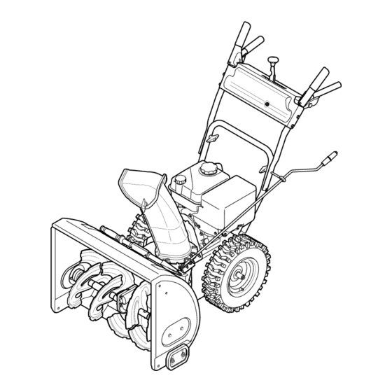
- Page 12 Shift Lever Drive Control Auger Control Gas Cap ChuteAssembly Oil Fill _jjjj Chute Directional Control \\\\ Mumer RecoilStarter ndle Auger Housing Augers Skid Shoes Figure10 Nowthat youhaveset up yoursnowthrower,it'simportant to become acquainted with its controlsand features,Referto Figure10, The key is a safetydevice.It mustbe fully insertedin orderfor the engineto start, Remove SHIFT LEVER the key whenthe snowthroweris not in use,...
- Page 13 THROTTLE CONTROL The augercontrol is locatedon the left handle.Squeezethe control grip againstthe handleto engagethe augerand startsnowthrowing action.Releaseto stop. DRIVE CONTROL aiW' DRIVE CONTROL Thethrottlecontrolis locatedon the rearof the engine.It regulatesthe speedof theengine and will shutoff the enginewhenmovedintothe STOPposition. Depressingthe primerforcesfuel directlyinto __<<<...
- Page 14 CLEAN-OUT TOOL • Refuelin a well-ventilated area with the enginestopped.Do not smokeor allowflamesor sparksin the areawherethe engineis refueledor wheregasolineisstored. Neveruse yourhandsto cleara cloggedchute assembly.Shut • Donot overfillthe fueltank.After refueling,makesurethe tank off engineand remainbehindhandlesuntilall movingpartshave cap is closed properlyand securely. stoppedbeforeusingthe clean-outtoolto clear thechute assembly. •...
- Page 15 TO ENGAGE DRIVE Movethrottlecontrolto FAST(rabbit)_T position. With the throttlecontrolin the Fast(rabbit) '_ position,move Movechoketo the CHOKE IJl position(coldenginestart). If shiftleverintoone of thesix forward(F) positionsor two reverse engineis warm,placechokein RUNposition. (R) positions.Selecta speedappropriatefor the snowconditions Pushprimerthree (3) times, makingsureto covervent hole in and a paceyou'recomfortable with.
- Page 16 MAINTENANCE SCHEDULE Before performing anytype ofmaintenance/service, disengage all Followthe maintenance schedulegiven below.This chart describes controls and stoptheengine. W aituntilall moving partshavecometo serviceguidelinesonly. Usethe ServiceLog columnto keeptrackof a completestop.Disconnect sparkplugwireandgroundit against t he completedmaintenance tasks.To locate the nearest Sears Service enginetoprevent u nintended starting. A lwayswearsafety glassesduring Centeror to scheduleservice,simplycontactSearsat 1-800-4-MY-HOME®.
- Page 17 Reinstallthe drain plugand tightenit securely. Refillwith the recommended oil and checkthe oil level.See Recommended Oil Usagechart.Theengine'soil capacityis 20 ounces. (%-400 -200 0o 200 400 Oil Drain ("c) -300 -200 -10° 0° Plug DONOTuse nondetergent o il or 2-strokeengineoil. It could shorten the engine'sservicelife.
- Page 18 become hot a nd can inc. LUBRICATION Gear Shaft Thegear (hex)shaft shouldbe lubricatedat least oncea seasonor afterevery 25 hoursof operation. Topreventspillage,removeall fuel fromtank by runningengine until it stops. Carefullypivotthe snowthrowerup and forwardso that it restson theauger housing. Removethe lowerframecover fromthe undersideof the snow throwerby removing the self-tappingscrewswhich secureit.
- Page 19 ADJUSTMENTS Shift Cable If thefull rangeof speeds(forwardand reverse)cannotbe achieved, referto the figureto the rightand adjustthe shift cableas follows: Placethe shiftleverin thefastest forward speedposition(F6). Loosenthe hex nuton the shiftcable indexbracket.See Figure Pivotthe bracketdownwardto take up slack in the cable. Retightenthehex nut. Drive Control Whenthedrivecontrol is releasedand in thedisengaged"up"position, the cableshouldhavevery little slack.It shouldNOTbe tight.
- Page 20 Auger Control "_ Referto the Assemblysectionfor instructions on adjustingtheauger controlcable. Skid Shoes Referto the Assemblysectionfor instructions on adjustingthe skid shoes. BELT REPLACEMENT Auger Belt To removeand replaceyoursnow thrower'sauger belt, proceedas follows: Topreventspillage,removeall fuel fromtank by runningengine until itstops. Removethe plasticbelt coveron the front of the engineby remov- ing the two self-tappingscrews.See Figure22.
- Page 21 6. Remove the belt a sfollows. Refer toFigure 25. A. Loosen and remove the shoulder screw w hich a cts a sabelt keeper. B. Unhook the auger brake b racket spring from the frame. 7. Remove the belt f rom around the auger pulley, and slip the belt between thesupport bracket and the auger pulley.
- Page 22 4, Carefully pivot the snow thrower upand forward so that i trests o n the auger housing. 5. Remove the frame c over from the underside ofthe snow thrower byremoving the self-tapping screws which s ecure it.Refer to Figure 24, 6.
- Page 23 NOTE:Be carefulnot to damagethe threadson the shaft, Carefullypositionthe hexshaftdownwardand to the left before carefullyslidingthe frictionwheelassemblyoff the shaft. See Figure31. NOTE: If you'rereplacingthe frictionwheelassemblyas a whole, discardthe wornpartand slidethe newpart ontothe hexshaft. Followthe stepsabovein reverseorderto reassemble components. Performthetest previouslydescribedin the Drive Control section.
- Page 24 If the snowthrowerwillnot be usedfor30 daysor longer,or if it is the end of the snowseasonwhenthe last possibilityof snowis gone,the equipmentneedsto be storedproperly.Followstorageinstructionsbelowto ensuretop performance from the snowthrowerfor manymoreyears. PREPARING SNOW THROWER PREPARING ENGINE Whenstoringthe snowthrowerin an unventilatedor metal stor- Enginesstoredover30 days need to be drainedof fuel to prevent age shed,careshouldbe taken to rustprooftheequipment.Using deterioration and gumfrom formingin fuel systemor on essential a light oil or silicone,coat theequipment,especiallyanychains,...
- Page 25 Enginefails to start Chokecontrolnot in CHOKEposition. Movechokecontrolto CHOKEposition. Sparkplugwire disconnected. Connectwireto sparkplug. Faultysparkplug. Clean,adjustgap,or replace. Fueltank emptyor stalefuel. Filltank with clean,freshgasoline. Enginenot primed. Primeengineas instructedin the OperationSection. Keynot inserted. Insertkeyfully intothe switch. Connectone end of the extensioncordto the electric Extensioncordnot connected(when usingelectricstartbutton,on modelsso starteroutletand the otherend to a three-prong equipped).
- Page 26 Craftsman Snow Thrower IViodel 247.881720 ///'...
- Page 27 Craftsman Snow Thrower IViodel 247.881720 731-2635 Snow Removal T oolMount 684-04107-0637 SpiralAssembly,LH 684-04057A-0637 ImpellerAssembly,12"Dia. 684-04108-0637 SpiralAssembly,RH 710-0347 HexScrew,3/8-16, 1.75,Gr5 731-04870 Spacer,1.25OD x .75 ID x 1.00 736-0188 710-0451 Bolt,Carriage,5/16-18,.750Grl Washer,Flat,.76x 1.49x .06 710-04484 Screw, 5/16-18, 0 .750 741-0493A Bushing,Flange,.80 ID x .91OD 710-0703 Screw,Carriage,1/4-20,.750,Gr5...
- Page 28 Craftsman Snow Thrower Model 247.881720 =\!Sj)
- Page 29 Craftsman Snow Thrower IViodel 247.881720 " 631-04133A HandleAssembly,ClutchLock,LH 749-04138A-0637 Handle,Lower 631-04134B HandleAssembly,ClutchLock,RH 935-0199A Bumper,Rubber,.62 ODx .22 736-0262 Washer,Fiat, .385x .870x .092 684-04105B HandleAss'y,Engage,LH 684-04106C HandleAss'y,Engage,RH 738-04118 Bolt, Shoulder,5/16-18x 0.905 738-04348 Screw,Shoulder,.43x 1.3,1/4-20 J631-04131B JChute, Lower(Inc/_Ref.# 27,Qty.3) 712-04064 Nut,FlangeLock,1/4-20 731-04869A Chute,FlangeKeeper...
- Page 30 Craftsman Snow Thrower IViodel 247.881720...
- Page 31 Craftsman Snow Thrower IViodel 247.881720 656-04055 DiscAssembly,FrictionWheel 731-04873 Spacer,1.25x .75x 3.0 938-04168 Axle, .75x 22" 684-04153 FrictionWheelAssembly,5.50D 736-0329 Washer,Lock, 1/4 684-04154B-0637 SupportBracket,FrictionWheel 684-04156A Shift Assembly,Rod 710-0809 Hex Screw,1/4-20,1.25,Gr5 710-0191 Hex Screw,3/8-24, 1.25,Gr8 J 710-0627 J HexScrew,5/16-24,.750,Gr5 710-0788 Screw,1/4-20,1.000 710-0672 Hex Screw,5/16-24,1.25,Gr5 710-1652 Screw,1/4-20x .625...
- Page 32 Craftsman Engine Model 265=SUA For Snow Model 247.881720 951-11282 MufflerAssembly 710-05001 StudM8x36 751-14190 MufflerStud Kit 951-11289 ExhaustPipe Gasket 712-04214 Nut,M8 710-04915 Bolt M6x12 951-10642B MufflerShield...
- Page 33 Craftsman Engine Model 265=SUA For Snow Model 247.881720 °0 951-10634 Air CleanerHousing 712-04213 951-11284 ChokeKnob 951-10757 ThrottleControlKnob 951-10637 KeySwitch 731-05632 951-10640 Choke PushRod 951-10635 HeaterBox 710-04943 Bolt M6x28...
- Page 34 Craftsman Engine Model 265=SUA For Snow Model 247.881720 132- 6asket Kit-Complete 133- 6asket Kit-External 134- Complete Engine...
- Page 35 Craftsman Engine IViodel 265=SUA For Snow IViodel 247.881720 951-11688 710-04932 Bolt M8x32 PistonRingSet 951-11632 951-11283 PistonPin Snap Ring Oil FillPlugAssembly 951-11900 Piston 951-11577 O-Ring15.8x2.5 951-11901 PistonPin 951-11368 Oil Seal,25x41.25x6 710-04915 Bolt M6x12 951-11248A CrankcaseKit 951-11113 Air Shield (Incl.59,62,74,75,79) 951-11573 951-11062B...
- Page 36 Craftsman Engine Model 265=SUA For Snow Model 247.881720 _'45 132- Gasket Kit-Complete 133-Gasket Kit-External 134- Complete Engine...
- Page 37 Craftsman Engine IViodel 265=SUA For Snow IViodel 247.881720 710-04968 Bolt M6x16 951-11054A ValveCover 731-07059 BreatherHose 726-04101 BreatherHose Clamp 951-11565 ValveCoverGasket 951-12000 ValveSpring Retainer(Intake) 951-11892 RockerArmAssembly 751-11124 Nut, PivotLocking 751-11123 AdjustingNut ,Valve 951-11893 RockerArm 710-04902 Bolt, Pivot 951-12002 ExhaustLashCap 951-12003 ValveSpring Retainer(Exhaust)
- Page 38 Craftsman Engine IViodel 265=SUA For Snow IViodel 247.881720 135 - Carburetor Kit...
- Page 39 Craftsman Engine IViodel 265=SUA For Snow IViodel 247.881720 710-04939 Stud M6x117 710-04910 Stud M6x105 951-11567 CarburetorInsulatorGasket 951-11896 CarburetorInsulator 951-11569A CarburetorGasket 951-10639A PrimerAssembly 951-11824 PrimerBulb 951-12705 Carburetor Assembly 951-11897 CarburetorGasketPlate 951-11112 ChokeControl 951-14050 CarburetorKit (Incl.h,n,o,p,q,r,s,t,v,x) ChokeShaft ChokePlate ThrottleShaft ThrottlePlate Screw M3x6...
- Page 40 Craftsman Engine Model 265-SUA For Snow Model 247.881720 92/° _3 92-_ _/93 951-10646 IgnitionCoil Assembly 951-11110 Air FlowShield 710-04940 BoltM6xlO 710-04919 BoltM6x25 951-12416 Flywheel 951-10934 CoolingFan 951-10911 Starter Cup 712-04209 Nut,Special,M14x1.5 710-04915 BoltM6x12 951-10663A BlowerHousing 736-04455 Gasket6 710-04974 BoltM6xlO 951-14151...
- Page 41 Craftsman Engine Model 265=SUA For Snow Model 247.881720 ,115 _--117 951-10758 PrimerBracket 951-11914 DipstickDecorationCover 710-05103 BoltM6x12 710-04905 Bolt 951-11108 710-04915 Bolt M6x12 GovernorSystemShield 951-11935 951-11913 GovernorSpring Oil FillTubeAssembly 951-10664 951-11381 ThrottleLinkageSpring O-Ring 951-10665 951-10656 Oil FillTube ThrottleLinkage 951-11106 GovernorArm 951-11904...
- Page 42 Craftsman Engine Model 265=SUA For Snow Model 247.881720 _128 1119 710-04914 BoltM6xlO 951-11680 i 120 WireClip 951-11114 1121 SwitchHousingMountingBracket 712-05015 i 122 Nut,M6 710-04935 BoltM4x60 i 123 710-04965 BoltM4x55 i 124 710-05182 BoltM6x32 i 125 715-04088 DowelPin8x8 i 126 951-10645A...
- Page 43 Craftsman Snow Thrower IViodel 247.881720 777S32636 1001 InO-NVqlO 777X43688 7VANV_ 8,HOIVH3dO QV3H"f! "S33VdHAS 13AVH9NO9NIlV_]dO N3HM NOIIAV3 VHIX3 3Sfl"SH3ONVIS18 IV 3OHVHOSIO / USEE85 ORFUEL 133810 8]A]N 'S318AFNI $133r80 NMOUHL QIOAV 01 "_ "3NIHOVW 9NIOIAH3S 80 9NIgOOlONA / CONTAINING MORE ', 3UOd38 O]dd01S]AVHSlUVdONIAO_ 3IV 311NA S3]QNVH THAN 10% ETHANOL ONIH38 NIVW3U QNV '3NION3 d OIS'SU3A33 H OIA33 39VgN3810 "8...
- Page 44 MTD CONSUMER GROUP INC (MTD), the California Air Resources Board (CARB) and the United States Environment Protection Agency (U. S. EPA) Emission Control System Warranty Statement (Owner's Defect Warranty Rights and Obligations) EMISSION CONTROLSYSTEM COVERAGE IS APPLICABLE TOCERTIFIEDENGINESPURCHASED IN CALIFORNIA IN 2005 ANDTHERE- AFTER,WHICHARE USEDIN CALIFORNIA, A NDTO CERTIFIED MODELYEAR2005 AND LATERENGINESWHICHARE PURCHASED AND USEDELSEWHERE IN THE UNITEDSTATES.
- Page 45 (6)The owner must not b echarged fordiagnostic labor that l eads tothe determination that a warranted part i sinfact d efective, provided that such diagnostic work i sperformed atawarranty station. (7) The engine manufacturer isliable f or d amages toother engine components proximately caused by afailure u nder warranty ofany warranted part.
- Page 46 Look For Relevant Emissions Durability Period and Air index information On Your Engine Emissions Label Engines that are certified to meet the California Air Resources Board (CARB) Tier 2 Emission Standards must display information regarding the Emissions Durability Period and the Air Index. Sears Brands Management Corporation makes this information available to the consumer on our emission...
- Page 47 Congratulations on making a smart purchase. Your new Craftsman® product is designed manufactured for years of dependable operation. But like all products, it may require repair from time to time. That's when having a Repair Protection Agreement can save you money and aggravation.
- Page 48 Los productosdefectuososser_.n reparadossin costoo reemplazados sin costosi la reparaci6nno est,. disponiNe. Paraobtener informaci6n sobre el alcance de la garantiay solieitar la reparaci6no el reemplazo, v isiteel sitio Web: www.craftsman.com Esta garantia eubre 0NICAMENTElos defectos en los materiales y en la mano de obra. Esta garantia NOcubre: •...
- Page 49 Lapresencia deeste sfrnbolo indica que se trata deinstrucciones Esta rn_.quina r ue construidapara seroperadade acuerdocon irnportantes deseguridad que sedeben r espetar para evitar las reglasde seguridadcontenidasen este manual.AI igualque poner enpeligro suseguridad personal y/omaterial yladeotras concualquiertipo de equipo rnotorizado, u n descuidoo error por personas.
- Page 50 Manejo seguro de la gasolina • Nuncaoperela rn_.quina si falta un rnontajedel canalo si el rnisrnoest,. daSado.Mantengatodos losdispositivosde seguri- Paraevitar lesiones personales 0 daSosrnateriales tengarnucho dad en su lugaryen funcionarniento. cuidadocuandotrabajecon gasolina.La gasolinaes surnarnente inflarnabley sus vaporespuedencausarexplosiones. S i se derrarna •...
- Page 51 • Paraencenderel motor,jale de la cuerdalentarnente hasta que • SegOn la Cornisi6nde Seguridad de Productosparael Consurni- sienta resistencia,luegojale r_.pidarnente. El replieguer_.pido de dor de los EstadosUnidos(CPSC)y la Agenciade Protecci6n la cuerdade arranque(tensi6nde retroceso)le jalar_,la rnanoy Arnbiental d e los EstadosUnidos(EPA),este productotieneuna el brazohaciael motor rn_.s r_.pido de Io que usted puedesoltar.
- Page 52 SiMBOLOS DE SEGURIDAD Esta p_ginadescribelossirnbolosy figurasde seguridadinternacionales que puedenapareceren este producto.Lea el manualdel operador )araobtenerla inforrnaci6n terrninadasobreseguridad,reunirse,operaci6ny rnantenimiento y reparaci6n. LEA ELMANUAL DELOPERADOR(S) Lea,entienda, y siga todas lasinstrucciones en el manual (es)antes de intentar reunirse y funcionar. LA ADVERTENCIA -- PLATOS ROTATORIOS Guarde manos de entrada y aperturas de la descarga mientras la m_iquina corre.
- Page 53 NOTA:las referencias al lado derechoo y ciertosde la m_.quina quitanievese determinan desdela parteposteriorde la unJdad en posicJ6n de operacJ6n (permaneciendo directamente detr_.s de la m_.quina quitanJeve, mirandohaciael panelde la manija), EXTRACCION DE LA UNIDAD DE LA CAJA Corte lasesquinasde la cajade cart6ny exti6ndalaen el piso Quitey descartetodoslos insertos de empaque.
- Page 54 SitOeel montajedel canalsobrela base.Vea la figura3. Cierrelosfijadoresde la brida para asegurarel montajedel canal a la basedel canal. Veala figura4. Losfijadoresde la brida emiten un chasquidocuandoest_.nbien asegurados. NOTA:si losfijadoresde la brida no seajustanen su lugarf_.clmente, utilice la palmade su rnanopara aplcar una presi6nr_.pida y firme en la parteposteriorde cadauno.
- Page 55 CONFIGURACION Herramienta de Lirnpieza del Canal Hay una herrarnienta de lirnpiezadel canal iajustada a la parte superiorde la caja de la barrenacon un pasadorde ensarnNado.Vea la figura6. La herrarnientaestAdiseSadaparalirnpiarel hieloy la nievedel rnontajede un canal. Este productose sujetarnedianteuna Herramienta de unbn de cableen la f_.brica.
- Page 56 Paraajustar laszapatasantideslizantes: Aflojelas cuatrostuercashexagonales (dosen cada lado)y los pernosdel carro. Muevalas zapatasantideslizantes a la posici6n deseada.Vea la figura7. Cornpruebe que toda la superficieinferiorde laszapatas antideslizantes est_contra el sueloparaevitar un desgaste desparejode los rnisrnos. Vuelvaa ajustarbien lastuercasy lospernos. Canal Es posibleajustarla distanciaa la cualse arroja la nievecarnbiandoel _.ngulo del canal superior.Parahacerlo: Detengael motorquitandola Ilavede encendidoy aflojela perilla a rnariposade pl_.stico que se encuentraen el lado izquierdodel...
- Page 57 Haydos velocidadesde retroceso(R). La uno (1) es la rn_.s lenta,y la dos (2) es la rn_.s r_.pida. Cumple con los estandares de seguridad de ANSi LasrnAquinas quitanievede Craftsman curnplen conlosestAndares d e seguridad del instituto estadounidense de est&ndares nacionales ( ANSI).
- Page 58 CONTROL DEL REGULADOR El controlde (abarrenaest,. ubicadoen (amanijaizquierda.Apriete la empu_adurade controlcontra la manijapara engranarla barrenay empiecea quitarnieve.Sueltepara que se detenga. CONTROL DE LA TRANSMISION El control del regulador estfi ubicado en la parte trasera del motor. /s CONTROL DE LA Negula la velocidad del motor, y Io apaga cuando se Iocoloca en la TRANSIVi|S|()N posicidn STOP (detencidn).
- Page 59 hacerque el motorgenerehurno,que cuestearrancarloo fallas en la HERRAIVllENTA DE LINIPIEZA bujia. La herrarnienta de lirnpiezadel canalesta ajustadaconvenienternente Vuelvaa colocarel tap6n/la varillade aceite y ajustecon firrneza a la parte posteriorde la caja de la barrenacon un pasadorde ensarn- antesde arrancarel motor. Gasolina Utilicegasolinapara autorn6viles (sin plornoo con bajo contenidode Nuncause sus rnanosparaliberar un rnontajede canaltapado.Antes I...
- Page 60 Arrancador el_ctrico Muevala palancadel cebadorhastala posici6nCHOKEIJl (encendidoconel motoren fifo). Si el motoryaest,. caliente, ubiqueel cebadoren la posici6nOFR El arrancadorel_ctricoopcionalest&equipadocon un cablede ali- Presioneel cebadortres (3) veces,asegur_.ndose d e cubrirel rnentaci6ny un enchufede tres terrninales conectadosa tierray est,. orificiode ventilaci6ncuandoIo haga.Si el motorest,. caliente, dise_adopara operarcon corrientedorn_sticade 120voltios.
- Page 61 LISTA DE MANTENIMIENTO Antes de realizarcualquiertipo del rnantenirniento/servicio, suelte Siga la lista de rnantenirniento dada abajo.Esta carta describepautas todos los rnandosy pare el motor.Esperehastaque todas las partes de servicios61o. U sela colurnnade Troncode Serviciopara guardar de rnovirniento hayanvenidoa una paradacornpleta.Desconecte el la pista de tareas de rnantenirniento cornpletadas.
- Page 62 Cambio de aceite del motor NOTA:Cambieel aceitedespu_sde las5 primerashorasde operaci6ny despu_sde cada50 horasde operaci6no una vez por temporada. Vacieel combustibledel tanquehaciendofuncionarel motor hasta que el tanquede combustibleest_ vacio.Cerci6resede que la tapadel combustible est,. asegurada. Coloqueun recipienteadecuadopara recolectarel aceitebajo el tap6nde drenajede aceite. Retireel tap6nde drenajede aceite.Vea la Figura12.
- Page 63 iilIi,,, Mida la separaci6nde bujia con un calibrador.Corrijade ser necesariotorciendoel electrodolateral.Veala Figura14.La separaci6ndebeestablecerseentre0,02y 0,03 pulgadas Electrodo (0,60-0,80ram). Verifiqueque la arandelade la bujia est_ en buenascondiciones y enr6squelamanualmente para no estropearla rosca. Unavez que la bujfaest_ colocada,apri_telacon unaIlave para comprimirla arandela. NOTA:Cuandoinstaieuna bujia nueva,una vez colocadala bujia apriete1/2vuelta paracomprimirla arandela.Cuandovuelvaa co[ocar una bujfausada,una vez colocadala bujia apriete1/8- 1/4de vuelta...
- Page 64 PLACA DE RASPADO Y ZAPATAS ANTIDESLIZANTES La placade raspadoy laszapatasantideslizantesubicadasen la base de la rn_.quina quitanieveest_.n sujetasa desgaste.Peri6dicarnente deberiacontrolarlos pernosy reernplazarlos cuandosea necesario. NOTA:Laszapatasde esta rn_.quina tienendos hordesde desgaste. Cuandoun lado se desgasta,se las puede rotar 1800 para usarel otto horde.
- Page 65 b, Afloje l atuerca h exagonal inferior del s oporte del c able d ela transmisi6n, Yea lafigura 1 9, c, Ubique lam6nsula hacia a rriba p ara brindar m_.s juego ( o hacia a bajo p ara a umentar latensi6n del c able), d, Vuelva aapretar latuerca hexagonal superior,...
- Page 66 Aflojey retireel tornHIo con rebordeque actQa como guarda de la correa.Vea la figura24. Desenganche el resortede la rn_nsulade soportedel marco. Retirela correade alrededorde la poleade la barrenay desNce la misrnaentre la rn_nsulade soportey la polea de la barrena. Vea la figura25. Para reaNzar e l reensarnblado de la correade la barrenasiga las instruccionesen orden inverso.
- Page 67 4. Girecon cuidadola rn_.quina quitanievehaciaarribay hacia delantede rnaneraque quedeapoyadasobrela cajade la barrena. 5. Saquela cubiertadel marcodesdedebajode la rn_.quina q uita nieveretirandolostornillosautorroscantes que la aseguran.Veala figura23. 6. Detr_.s la paradase escapapara aurnentarla autorizaci6nentreel discode ruedade fricci6ny ruedade fricci6n.Vea la figura27. 7. Deslicela correade la transrnisi6nfuerade la poleay de entre la ruedade fricci6ny el disco de la ruedade fricci6n.Vea la figura 8.
- Page 68 NOTA:Tengacuidadode no daSarlas roscasdel eje....i ....Con cuidado,ubiqueel eje hexagonalhaciaabajo y haciala izquierdaantesde deslizarcon precauci6nel rnontajede la rueda de fricci6nfueradel eje.Vea la figura30. NOTA:Cuandose deseareernplazar e l conjuntode la ruedade fricci6ncornpleto, d escartela piezadesgastaday deslicela nueva piezaen el eje hexagonal. Parareensarnblar l os cornponentes siga los pasosanteriores en orden inverso.
- Page 69 Si no sevaa utiliza el equipo durante30 dfaso rn_.s, o sies el finalde la ternporada de nievey ya noexisteposibilidad deque nieve, e s necesario alrnacenar e l equipo de rnanera adecuada. S igalasinstrucciones d e alrnacenarniento quese indicana continuaci6n p aragarantizar e l rendirniento rn_.xirno d e la rn_.quina q uitanieve durante rnuchos a_os.
- Page 70 El motorno arranca La palancade obturaci6nno est,. en la Pongael interruptor en la posici6nCHOKE(obtura- posici6nON (encendido) ci6n). Se ha desconectado el cablede la bujia Conecteel cablea la bujfa. La bujia nofunciona correctamente Limpie,ajustela distanciadisruptivao cambie. El tanquede combustibleest,. vado o el Lleneel tanquecongasolinalimpiay fresca.
- Page 71 Dernasiada vibraci6n Hay piezasque est_.n fiojas o la barrena Detengael motorde inrnediatoy desconecteel est,. dafiada cablede la bujia.Ajuste todoslos pernosy las tuercas.Si la vibraci6ncontinQa. I levela unidada reparara un centrode partesy reparaci6nSears. Perdidade potencia El cable de la bujfaest,. flojo Conectey ajusteel cablede la bujfa.
- Page 72 MTD CONSUMER GROUP, iNC. (MTD), el Bordo de Recursos de Aire de California (CARB) y la Agencia de Protecci6n Medioambiental de Estados Unidos (U. S. EPA) Declaraci6n de Garantia del Sistema de Control de Emisiones (Derechos y obligaciones del propietario seg_n la garantia contra defectos) LA COBERTURADESISTEMADECONTROLDEEMISIONES APLICABLE A MOTORES CERTIFICADOS COMPRADOS ENCALIFORNIA EN2005 Y A PARTIRDE ENTONCES, QUESON USADOS EN CALIFORNIA, Y HASTA ANO2005 DE MODELOCERTIFICADO Y MOTORES POSTERIORES QUESON COMPRADOS Y USADOSENOTRAPARTEEN LOSESTADOS UNIDOS.
- Page 73 (3) Cualquier pieza g arantizada que est_ prograrnada para reernplazo segQn elrnantenirniento requerido deconforrnidad con lasinstruc- clones escritas delaSubsecci6n (c)segarantiza por e lperiodo detiernpo anterior alaprirnera fecha d ereernplazo prograrnada para e sa pieza. Silapieza f alla antes del p rimer reernplazo programatic, larnisrna ser_.
- Page 74 Busque el periodo de duraci6n de emisiones importantes yla informaci6n de clasificaci6n de aire en la etiqueta de emisiones de su motor Los motores cuyo cumpiimiento con los estAndares de emisi6n Tier 2 de la Comisi6n de Recursos Ambientales de California (CARB) est6 certificado deben exhibir la informaci6n relacionada con el periodo de duraci6n de ias emisiones y la clasificaci6n de aire.
- Page 75 Felicitaciones por haber realizado una adquisici6n inteligente. El producto Craftsman® que ha adquirido esta diseSado y fabricado para brindar muchos aSos de funcionamiento confiable. Pero como todos los productos a veces puede requerir de reparaciones. Es en ese momento cuando...
- Page 76 Your Home For troubleshooting, product manuals and expert advice: managernylife www.managemylife.com For repair - in your home - of all major brand appliances, lawn and garden equipment, or heating and cooling systems, no matter who made it, no matter who sold it! For the replacement parts, accessories owner's manuals that you need to do-it-yourself.