Table of Contents
Advertisement
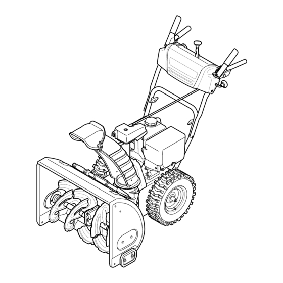
Operator's
Manual
CRRFr MRN
24" SNOW THROWER
Model No. 247.881730
CAUTION"
Before
using this
product,
read this manual
and
follow
all safety
rules and operating
instructions.
,, SAFETY
o ASSEMBLY
OPERATION
MAINTENANCE
PARTS LIST
o ESPANOL
Sears Brands
Management
Corporation,
Hoffman
Estates,
IL 60179, U.S.A.
Visit our website:
www.craftsman.com
FormNo. 769-08174B
(July9, 2012)
Advertisement
Table of Contents

Related Manuals for Craftsman 247.881730


Summary of Contents for Craftsman 247.881730
- Page 1 Operator's Manual CRRFr MRN 24" SNOW THROWER Model No. 247.881730 ,, SAFETY o ASSEMBLY OPERATION MAINTENANCE CAUTION" Before using this PARTS LIST product, read this manual o ESPANOL follow all safety rules and operating instructions. Sears Brands Management Corporation, Hoffman Estates, IL 60179, U.S.A.
- Page 2 Searsauthorizedserviceprovider. W ith proofof purchase, youwill receivea newchutefree of charge.Youare responsible for the laborcost of installationand any costincurredto verify thedefect. Forwarrantycoveragedetailsto obtainrepairor replacement, v isitthe web site:www.craftsman.com This warrantycoversONLYdefectsin materialand workmanship. W arrantycoveragedoes NOTinclude: •...
- Page 3 This machinewas builtto be operatedaccordingto the safeopera- This symbolpointsout importantsafetyinstructionswhich,if not tion practicesin this manual.As with anytype of powerequipment, followed,couldendangerthepersonalsafetyand/orpropertyof carelessnessor error on the partof the operatorcan resultin serious yourselfand others. Readand followall instructionsin this manual injury.This machineis capableof amputatingfingers,hands,toes beforeattemptingto operatethis machine.Failureto complywith and feet and throwingdebris.Failureto observethe followingsafety these instructionsmay resultin personalinjury.Whenyou seethis...
- Page 4 Safe Handling of Gasoline • Exerciseextremecautionwhenoperatingon or crossinggravel surfaces.Stay alertfor hidden hazardsor traffic. Toavoidpersonalinjuryor propertydamageuseextremecare in handlinggasoline.Gasolineis extremelyflammableand the vaporsare Exercisecautionwhenchangingdirectionand whileoperatingon explosive.Seriouspersonalinjurycan occurwhengasolineis spilled slopes.Do notoperateon steep slopes. on yourselfor yourclotheswhichcan ignite. Washyour skin and Planyoursnow-throwing patternto avoiddischargetowards changeclothesimmediately. windows,walls,cars etc.
- Page 5 MAINTENANCE & STORAGE DO NOT MODIFY ENGINE • Nevertamperwith safetydevices.Checktheirproperoperation Toavoidseriousinjuryor death,do not modifyengine in any way. regularly.Referto the maintenance and adjustmentsectionsof Tampering with the governorsettingcanlead to a runawayengineand this manual. cause it to operateat unsafespeeds.Nevertamperwithfactory setting of engine governor. •...
- Page 6 SAFETY SYMBOLS This pagedepictsand describessafetysymbolsthat mayappear on this product. Read,understand,and followall instructionson the machine beforeattemptingto assembleand operate. READ THE OPERATOR'S MANUAL(S) Read, understand, and follow all instructions in the manual(s) before attempting to assemble operate WARNING-- ROTATING BLADES Keep hands out of inlet and discharge openings while machine is running.
- Page 7 Thispage leftintentionally blank.
- Page 8 NOTE:References to rightor left sideof the snowthrowerare determined from behindthe unit in the operatingposition(standing directlybehindthe snow thrower,facingthe handlepanel). REMOVING FROM CARTON Cut the cornersof thecarton and lay the sidesflat on the ground. Removeand discard all packinginserts. Movethe snowthrowerout of thecarton. Makecertainthe carton has beencompletelyemptiedbefore discardingit.
- Page 9 Placechuteontochute baseand securechutecontrol headto chutesupport bracketwith clevispin and cotterpin removed earlier.See Figure4. Finishsecuringchutecontrolhead to chutesupport bracketwith wingnut and hexscrewremovedearlier.See Figure5. Insertthe chutedirectionalcontrol intothe supportbracketon the rear of thedash panel.See Figure6. Removethehairpinclip from the rear of thechute controlhead. Insertchutedirectionalcontrolinto rearof the chutecontrol head. Securethe chutedirectionalcontrolto the chutecontrolhead with the hairpinclip removedearlier.See Figure7.
- Page 10 SET-UP Chute Clean-Out Tool ......A chute clean-out tool is fastenedto the top of the augerhousing with a mountingclip. See Figure8. The tool is designedto cleara :: :/4Y ..chuteassemblyof ice and snow.This item is fastenedwith a cabletie at the factory.Cut thecable tie beforeoperatingthe snowthrower. Chute Clean-Out Tool Neveruseyour handsto cleara cloggedchuteassembly.Shut...
- Page 11 Makecertain theentirebottomsurfaceof skid shoeis againstthe groundto avoidunevenwearon the skid shoes, Refightennutsand bolts securely, Chute Assembly Thedistancesnowis throwncan be adjustedby changingthe angle of the chuteassembly,Todo so: Stopthe engineby removingthe ignitionkeyand loosenthe plasticwingknobfoundon the left sideof the chuteassembly. Pivotthe chute upwardor downwardbeforeretightening thewing knob,See Figure10, Auger Control Priorto operatingyoursnowthrower,carefullyreadand follow all...
- Page 12 Shift Lever Drive Control Auger Control GasCap Chute Directional Control ChuteAssembly Recoil Starter Handle _uger Housing_ Throttle ,L!, Control Choke Control :lectric Start Augers Button "Skid Shoe Oil Drain Electric Starter Outlet Figure12 Nowthat youhaveset up yoursnowthrower,it'simportant to become acquainted with itscontrolsand features,Referto Figure12, The key isa safetydevice.It mustbe fully inserted in orderfor the engineto start.
- Page 13 THROTTLE CONTROL The augercontrol is locatedon the left handle.Squeezethe control grip againstthe handleto engagethe augerand startsnowthrowing action.Releaseto stop. DRIVE CONTROL/AUGER CONTROL LOCK aiW' DRIVE CONTROL Thethrottlecontrolis locatedon the rearof the engine.It regulatesthe speedof theengine and will shutoff the enginewhenmovedintothe STOPposition. Depressingthe primerforcesfuel directlyinto ___144 the engine'scarburet°rt°...
- Page 14 CLEAN-OUT TOOL • Refuelin a well-ventilated area with the enginestopped.Do not smokeor allowflamesor sparksin the areawherethe engineis refueledor wheregasolineisstored. Neveruse yourhandsto cleara cloggedchute assembly.Shut • Donot overfillthe fueltank.After refueling,makesurethe tank off engineand remainbehindhandlesuntilall movingpartshave cap is closed properlyand securely. stoppedbeforeusingthe clean-outtoolto clear thechute assembly. •...
- Page 15 TO ENGAGE DRIVE Movethrottlecontrolto FAST(rabbit)_T position. With the throttlecontrolin the Fast(rabbit) '_ position,move Movechoketo the CHOKE IJl position(coldenginestart). If shiftleverintoone of thesix forward(F) positionsor two reverse engineis warm,placechokein RUNposition. (R) positions.Selecta speedappropriatefor the snowconditions Pushprimerthree (3) times, makingsureto covervent hole in and a paceyou'recomfortable with.
-
Page 16: Checking/Changing Engine Oil
MAINTENANCE SCHEDULE Before performing anytype ofmaintenance/service, disengage all Followthe maintenance schedulegiven below.This chart describes controls and stoptheengine. W aituntilall moving partshavecometo serviceguidelinesonly. Usethe ServiceLog columnto keeptrackof a completestop.Disconnect sparkplugwireandgroundit against t he completedmaintenance tasks.To locate the nearest Sears Service enginetoprevent u nintended starting. A lwayswearsafety glassesduring Centeror to scheduleservice,simplycontactSearsat 1-800-4-MY-HOME®. -
Page 17: Checking Spark Plug
Reinstallthe drain plugand tightenit securely. Refillwith the recommended oil and checkthe oil level.See Recommended Oil Usagechart.Theengine'soil capacityis 20 ounces. (%-400 -200 0o 200 400 Oil Drain ("c) -300 -200 -10° 0° Plug DONOTuse nondetergent o il or 2-strokeengineoil. It could shorten the engine'sservicelife. - Page 18 become hot a nd can inc. LUBRICATION Gear Shaft Thegear (hex)shaft shouldbe lubricatedat least oncea seasonor afterevery 25 hoursof operation. Topreventspillage,removeall fuel fromtank by runningengine until it stops. Carefullypivotthe snowthrowerup and forwardso that it restson theauger housing. Removethe lowerframecover fromthe undersideof the snow throwerby removing the self-tappingscrewswhich secureit.
- Page 19 ADJUSTMENTS Shift Cable If thefull rangeof speeds(forwardand reverse)cannotbe achieved, referto the figureto the rightand adjustthe shift cableas follows: Placethe shiftleverin thefastest forward speedposition(F6). Loosenthe hex nuton the shiftcable indexbracket.See Figure Pivotthe bracketdownwardto take up slack in the cable. Retightenthehex nut. Drive Control Whenthedrivecontrol is releasedand in thedisengaged"up"position, the cableshouldhavevery little slack.It shouldNOTbe tight.
- Page 20 Auger Control "_ Referto the Assemblysectionfor instructions on adjustingtheauger controlcable. Skid Shoes Referto the Assemblysectionfor instructions on adjustingthe skid shoes. BELT REPLACEMENT Auger Belt To removeand replaceyoursnow thrower'sauger belt, proceedas follows: Topreventspillage,removeall fuel fromtank by runningengine until itstops. Removethe plasticbelt coveron the front of the engineby remov- ing the two self-tappingscrews.See Figure24.
- Page 21 6. Remove the belt a sfollows. Refer toFigure 27. A. Loosen and remove the shoulder screw w hich a cts a sabelt keeper. B. Unhook the auger brake b racket spring from the frame. 7. Remove the belt f rom around the auger pulley, and slip the belt between thesupport bracket and the auger pulley.
- Page 22 4, Carefully pivot the snow thrower upand forward so that i trests o n the auger housing. 5. Remove the frame c over from the underside ofthe snow thrower byremoving the self-tapping screws which s ecure it.Refer to Figure 26, 6.
- Page 23 NOTE:Be carefulnot to damagethe threadson the shaft, Carefullypositionthe hexshaftdownwardand to the left before carefullyslidingthe frictionwheelassemblyoff the shaft. See Figure33. NOTE: If you'rereplacingthe frictionwheelassemblyas a whole, discardthe wornpartand slidethe newpart ontothe hexshaft. Followthe stepsabovein reverseorderto reassemble components. Performthetest previouslydescribedin the Drive Control section.
- Page 24 If the snowthrowerwillnot be usedfor30 daysor longer,or if it is the end of the snowseasonwhenthe last possibilityof snowis gone,the equipmentneedsto be storedproperly.Followstorageinstructionsbelowto ensuretop performance from the snowthrowerfor manymoreyears. PREPARING SNOW THROWER PREPARING ENGINE Whenstoringthe snowthrowerin an unventilatedor metal stor- Enginesstoredover30 days need to be drainedof fuel to prevent age shed,careshouldbe taken to rustprooftheequipment.Using deterioration and gumfrom formingin fuel systemor on essential a light oil or silicone,coat theequipment,especiallyanychains,...
- Page 25 Enginefails to start Chokecontrolnot in CHOKEposition. Movechokecontrolto CHOKEposition. Sparkplugwire disconnected. Connectwireto sparkplug. Faultysparkplug. Clean,adjustgap,or replace. Fueltank emptyor stalefuel. Filltank with clean,freshgasoline. Enginenot primed. Primeengineas instructedin the OperationSection. Keynot inserted. Insertkeyfully intothe switch. Connectone end of the extensioncordto the electric Extensioncordnot connected(when usingelectricstartbutton,on modelsso starteroutletand the otherend to a three-prong equipped).
- Page 26 Craftsman Snow Thrower IViodel 247.881730 ///'...
- Page 27 Craftsman Snow Thrower IViodel 247.881730 731-2635 Snow Removal T oolMount 684-04107-0637 SpiralAssembly,LH 684-04057A-0637 ImpellerAssembly,12"Dia. 684-04108-0637 SpiralAssembly,RH 710-0347 HexScrew,3/8-16, 1.75,Gr5 731-04870 Spacer,1.25OD x .75 ID x 1.00 736-0188 710-0451 Bolt,Carriage,5/16-18,.750Grl Washer,Flat,.76x 1.49x .06 710-04484 Screw, 5/16-18, 0 .750 741-0493A Bushing,Flange,.80 ID x .91OD 710-0703 Screw,Carriage,1/4-20,.750,Gr5...
- Page 28 Craftsman Snow Thrower Model 247.881730 ..] ,_12)
- Page 29 Craftsman Snow Thrower IViodel 247.881730 " 790-00341 Bracket,Rod 631-04133A HandleAssembly,ClutchLock,LH 790-00313-0637 Shift Lever 631-04134B HandleAssembly,ClutchLock,RH 710-04370 Screw,1/4-20x 3.00 684-04111B HandleAss'y,Engage,LH 710-0627 Screw,5/16-24x .750 684-041120 HandleAss'y,Engage,RH 710-04071 Bolt, Carriage, 5 /16-18,1.0 J 731-06440A J Chute,Lower 710-0451 Bolt, Carriage, 5 /16-18,.750 732-04238 Spring,Torsion,.8156ID x .3038...
- Page 30 Craftsman Snow Thrower IViodel 247.881730...
- Page 31 Craftsman Snow Thrower IViodel 247.881730 656-04055 DiscAssembly,FrictionWheel 731-04873 Spacer,1.25x .75x 3.0 938-04168 Axle, .75x 22" 684-04153 FrictionWheelAssembly,5.50D 936-0329 Washer,Lock, 1/4 684-04154B-0637 SupportBracket,FrictionWheel 684-04156A Shift Assembly,Rod 710-0809 Hex Screw,1/4-20,1.25,Gr5 710-0191 Hex Screw,3/8-24, 1.25,Gr8 J 710-0627 J HexScrew,5/16-24,.750,Gr5 710-0788 Screw,1/4-20,1.000 710-0672 Hex Screw,5/16-24,1.25,Gr5 710-1652 Screw,1/4-20x .625...
- Page 32 Craftsman Engine Model 270=SUA For Snow Model 247.881730 951-11282 MufflerAssembly 710-05001 MufflerStud 951-14190 MufflerStud Kit 951-11289 MufflerGasket 712-04214 Nut- M8 710-04915 Bolt- M6X 12Zin 951-10642B MufflerShroud...
- Page 33 Craftsman Engine Model 270=SUA For Snow Model 247.881730 °0 951-10634 Shroud-Engine 712-04213 951-11284 ChokeKnob 951-10757 ThrottleKnob 951-10637 Switch-Ignition 731-05632 IgnitionKeySwitch 951-10640 PushRod-Choke 951-10635 Air Filter Heating 710-04943 Bolt-M61X28MSpec...
- Page 34 Craftsman Engine IViodel 270=SUA For Snow IViodel 247.881730 131- 6asketKit-Complete 132-6asketKit-External 133- CompleteEngine...
- Page 35 Craftsman Engine IViodel 270=SUA For Snow IViodel 247.881730 951-12111 710-04932 Bolt PistonRingSet 951-11632 951-11283 PistonPin Snap Ring Oil FillPlugAssembly 951-12007 Piston 951-11577 O-Ring15.8X 2.5 951-11633 PistonPin 951-11368 Oil Seal 710-04915 Bolt- M6X 12Zin 951-11249 CrankcaseKit 951-11113 Shield- Air (Incl.59,62,74,75,79) 951-11573...
- Page 36 Craftsman Engine Model 270-SUA For Snow Model 247.881730 46 _46 U" -"45 131- Gasket Kit-Complete 132-Gasket Kit-External 133- Complete Engine...
- Page 37 Craftsman Engine IViodel 270=SUA For Snow IViodel 247.881730 710-04968 FlangeBoltM6 951-11054A ValveCover 731-07059 Hose-Breather 726-04101 Clamp-Breather H ose 951-11565 ValveCoverGasket 951-12000 IntakeValveSpring Retainer 951-11892 RockerArmAssembly 751-11124 Nut- Pivot Lockin 751-11123 Nut- ValveAdjust 951-11893 RockerArm 710-04902 Bolt- Pivot 951-12002 ExhaustValveAdjuster 951-12003...
- Page 38 Craftsman Engine IViodel 270=SUA For Snow IViodel 247.881730 134-Carburetor Kit - Deni 135 - Carburetor Kit - Huayi...
- Page 39 Craftsman Engine IViodel 270=SUA For Snow IViodel 247.881730 710-04939 Stud-Carb 710-04910 Stud- M6X 105 951-11567 Gasket-Carb insulator 951-11896 CarburetorInsulat 951-11569A CarburetorGasket 951-10639A Primer 951-11824 PrimerBulb 951-14026A Carburetor Assembly- Huayi 951-14027A Carburetor Assembly- Deni 951-11897 CarburetorGasket 951-11112 Bracket- ChokeControl 951-14154 CarburetorKit- Deni (Incl.h,n,o,p,q,r,s,t,u,x)
- Page 40 Craftsman Engine IViodel 270-SUA For Snow IViodel 247.881730 951-10646 IgnitionCoil 951-11110 Shield- Air Flow 710-04940 Bolt 710-04919 Bolt- FlangeM6 951-12416 Flywheel 951-10934 CoolingFan 951-10911 Starter Cup 712-04209 Nut- M14 710-04915 Bolt- M6X 12Zin 951-10663A FanCoverComplete 736-04455 FlatWasher-Recoil 710-04974 FlangeBolt M6...
- Page 41 Craftsman Engine IViodel 270=SUA For Snow IViodel 247.881730 ,114 _---115 97 9s 951-10758 951-11914 ThrottleControlAssembly Engine/Dipstick Cover 710-05103 Bolt-M6X 12 710-04905 Bolt 951-11108 Shield- Governor 710-04915 Bolt- M6X 12Zin 951-11935 951-11913 GovernorSpring Oil FillTubeAssembly 951-10664 951-11381 Spring-Throttle Return O-Ring 951-10665...
- Page 42 Craftsman Engine Model 270=SUA For Snow Model 247.881730 _127 1118 710-04914 Bolt- FlangeM6 951-11680 i119 FlexibleClamp 951-11114 i 120 Bracket- SwitchHousingMount 712-05015 1121 710-04965 Screw M4X 55 i 122 710-04935 Screw- M4X 60 i 123 710-05182 Bolt-M6X 32 i 124...
- Page 43 Craftsman Snow Thrower Model 247.881730 777S32636 777X43688 1001 J,nO-NV:llO 7VnNVW S,HOIVH3dOQV3H"G /IUSI_E85 OR FUEL "S3OVJHflS ] 3AVH9 H09NIlV_3d0 CONTAINING MORE N3HM N011nv3 V UIX]3sn"$830N¥1S181¥ 398VH3SI0 THAN10% ETHANOL 1O3Ul0 U3A3N 'S]lSnPNI 8133r80 NMOUHL QIOM 01 "_ "3NIHOVW 9NIOIAS]S80 9NI99033Nn 3UOJ38 o3aa01S3MH SIUVd9NIAO_J ] ]V ]llNn S3]ONVH QNIH38 NIV_3UQNV '3NIGH3 d OIS'SH]A3]HOlfl]O 30VON3SIQ "8...
- Page 44 MTD CONSUMER GROUP INC (MTD), the California Air Resources Board (CARB) and the United States Environment Protection Agency (U. S. EPA) Emission Control System Warranty Statement (Owner's Defect Warranty Rights and Obligations) EMISSION CONTROLSYSTEM COVERAGE IS APPLICABLE TOCERTIFIEDENGINESPURCHASED IN CALIFORNIA IN 2005 ANDTHERE- AFTER,WHICHARE USEDIN CALIFORNIA, A NDTO CERTIFIED MODELYEAR2005 AND LATERENGINESWHICHARE PURCHASED AND USEDELSEWHERE IN THE UNITEDSTATES.
- Page 45 (6)The owner must not b echarged fordiagnostic labor that l eads tothe determination that a warranted part i sinfact d efective, provided that such diagnostic work i sperformed atawarranty station. (7) The engine manufacturer isliable f or d amages toother engine components proximately caused by afailure u nder warranty ofany warranted part.
- Page 46 Look For Relevant Emissions Durability Period and Air index information On Your Engine Emissions Label Engines that are certified to meet the California Air Resources Board (CARB) Tier 2 Emission Standards must display information regarding the Emissions Durability Period and the Air Index. Sears Brands Management Corporation makes this information available to the consumer on our emission...
- Page 47 Congratulations on making a smart purchase. Your new Craftsman® product is designed manufactured for years of dependable operation. But like all products, it may require repair from time to time. That's when having a Repair Protection Agreement can save you money and aggravation.
- Page 48 Servicio y Mantenimiento ......Pagina 61 posterior Almacenamiento fuera de temporada ..Pagina 69 GARANTJA COMPLETA CRAFTSMAN POR DOS ANOS PORDOSANOSa partir de la fechade la cornpra,este productoest_ garantizadopor defectosen los rnateriales y la rnanode obra. Los productosdefectuososser&nreparadossin costoo reemplazados sin costosi la reparaci6nno est&disponible.
- Page 49 Esta rn_.quina r ue construidapara seroperadade acuerdocon La presenciade este sfrnboloindicaque setrata de instrucciones las reglasde seguridadcontenidasen este manual.AI igualque irnportantesde seguridadque se deben respetarpara evitar concualquiertipo de equipo rnotorizado, u n descuidoo error por poner en peligrosu seguridadpersonaly/o materialy la de otras partedel operadorpuedeproducirlesionesgraves.Esta rn_.quina personas.Lea y siga todaslas instruccionesde este manualantes es capazde arnputarrnanosy piesy de arrojarobjetoscon gran...
- Page 50 Manejo seguro de la gasolina • Nuncaoperela rn_.quina si falta un rnontajedel canalo si el rnisrnoest,. daSado.Mantengatodos losdispositivosde seguri- Paraevitar lesiones personales 0 daSosrnateriales tengarnucho dad en su lugaryen funcionarniento. cuidadocuandotrabajecon gasolina.La gasolinaes surnarnente inflarnabley sus vaporespuedencausarexplosiones. S i se derrarna •...
- Page 51 • Paraencenderel motor,jale de la cuerdalentarnente hasta que • SegOn la Cornisi6nde Seguridad de Productosparael Consurni- sienta resistencia,luegojale r_.pidarnente. El replieguer_.pido de dor de los EstadosUnidos(CPSC)y la Agenciade Protecci6n la cuerdade arranque(tensi6nde retroceso)le jalar_,la rnanoy Arnbiental d e los EstadosUnidos(EPA),este productotieneuna el brazohaciael motor rn_.s r_.pido de Io que usted puedesoltar.
- Page 52 SiMBOLOS DE SEGURIDAD Esta p_ginadescribelossirnbolosy figurasde seguridadinternacionales que puedenapareceren este producto.Lea el manualdel operador )araobtenerla inforrnaci6n terrninadasobreseguridad,reunirse,operaci6ny rnantenimiento y reparaci6n. LEA ELMANUAL DELOPERADOR(S) Lea,entienda, y siga todas lasinstrucciones en el manual (es)antes de intentar reunirse y funcionar. LA ADVERTENCIA -- PLATOS ROTATORIOS Guarde manos de entrada y aperturas de la descarga mientras la m_iquina corre.
- Page 53 NOTA:las referencias al lado derechoo y ciertosde la m_.quina quitanievese determinan desdela parteposteriorde la unJdad en posicJ6n de operacJ6n (permaneciendo directamente detr_.s de la m_.quina quitanJeve, mirandohaciael panelde la manija), EXTRACCI6N DE LA UNIDAD DE LA CAJA Corte lasesquinasde la cajade cart6ny exti6ndalaen el piso Quitey descartetodoslos insertos de empaque.
- Page 54 Lugar rampahasta la basede la tolva y la cabezasegurode controldel canalde soportedel conductocon el apoyode pasadorde horquillay pasadorquit6 antes.Vet Figura4. Terminede asegurarla cabezade controldel canalde soporte del conductode soportecon la tuercade mariposay el tornillo hexagonalretirados anteriormente. W ase la Figura5. Insertarel controldireccionaldel canal en el soportede apoyoen la partetraseradel tablerode instrumentos.
- Page 55 CONFIGURACION Herramienta de Lirnpieza del Canal Hayuna herrarnienta de lirnpiezadeJcanal iajustada a Ja parte superiorde la caja de la barrenacon un pasadorde ensarnNado.Vea la figura8. La herrarnienta estAdiseSadaparalirnpiarel hieloy la nievedel rnontajede un canal. Esteproductose sujeta rnedianteuna uni6nde cableen la f_.brica. C orte la uni6n de cable antesde operar la rnAquina quitanieve.
- Page 56 Paraajustar laszapatasantideslizantes: Aflojelas cuatrostuercashexagonales (dosen cada lado)y los pernosdel carro. Muevalas zapatasantideslizantes a la posici6n deseada.Vea la figura9. Cornpruebe que toda la superficieinferiorde laszapatas antideslizantes est_contra el sueloparaevitar un desgaste desparejode los rnisrnos. Vuelvaa ajustarbien lastuercasy lospernos. Ajuste del montaje del canal Es posibleajustarla distanciaa la cualse arroja la nievecarnbiandoel _.ngulo del rnontajedel canal.
- Page 57 Haydos velocidadesde retroceso(R). La uno (1) es la rn_.s lenta, y la dos (2) es la rn_.s r_.pida. Cumple con los estandares de seguridad de ANSI Lasrn_.quinas q uitanievede Craftsman curnplen con losestAndares d e seguridad del instituto estadounidense d e est&ndares n acionales (ANSI).
- Page 58 CONTROL DEL REGULADOR El controlde la barrenaest,. ubicadoen la manijaizquierda.Apriete la empu_adurade controlcontra la manijapara engranarla barrenay empiecea quitarnieve.Sueltepara que se detenga. CONTROL DE LA TRANSMISION/CONTROL DE LA BARRENA DE CERRADURA El control del regulador estfi ubicado en la parte trasera del motor. Negula la velocidad del motor, y Io apaga cuando se Iocoloca en la CONTROL DiE LA...
- Page 59 El controldireccionaldel canalsobrecargaest_ situadoen el centrode NOTA:No Io Ileneen exceso.El Ilenadoexcesivode aceitepuede la quitanievesentreel panel de asa y el mangoinferior.Paracarnbiar hacerque el motorgenerehurno,que cuestearrancarloo fallas en la la direcci6nen la que se lanzala nieve,gire el controldireccionaldel bujia. canal. Vuelvaa colocarel tap6n/la varillade aceite y ajustecon firrneza antesde arrancarel motor.
- Page 60 Arrancador el_ctrico Muevala palancadel cebadorhastala posici6nCHOKE I.,_1 (encendidoconel motoren fifo). Si el motorya est,. caliente, ubique el cebadoren la posici6nOFR El arrancadorel_ctricoopcionalest&equipadocon un cablede ali- Presioneel cebadortres (3) veces,asegur_.ndose d e cubrirel rnentaci6n y un enchufede tres terrninales conectadosa tierray est,. orificio de ventilaci6ncuandoIo haga.Si el motorest,.
- Page 61 LISTA DE MANTENIMIENTO Antes de realizarcualquiertipo del rnantenirniento/servicio, suelte Siga la lista de rnantenirniento dada abajo.Esta carta describepautas todos los rnandosy pare el motor.Esperehastaque todas las partes de servicios61o. U sela colurnnade Troncode Serviciopara guardar de rnovirniento hayanvenidoa una paradacornpleta.Desconecte el la pista de tareas de rnantenirniento cornpletadas.
- Page 62 Carnbio de aceite del motor NOTA:Carnbieel aceitedespu_sde las5 prirnerashorasde operaci6ny despu_sde cada50 horasde operaci6no una vez por ternporada. Vacieel combustibledel tanquehaciendofuncionarel motor hasta que el tanquede combustibleest_ vado. Cerci6resede que la tapadel combustibleest,. asegurada. Coloqueun recipienteadecuadopara recolectarel aceitebajo el tap6nde drenajede aceite. Retireel tap6nde drenajede aceite.Vea la Figura14.
- Page 63 Mida la separaci6nde bujia con un calibrador.Corrijade ser necesariotorciendoel electrodolateral.Veala Figura16.La separaci6ndebeestablecerseentre0,02y 0,03 pulgadas(0,60- Electrodo 0,80ram). Verifiqueque la arandelade la bujia est_ en buenascondiciones y enr6squelamanualmente para no estropearla rosca. Unavez que la bujfaest_ colocada,apri_telacon unaIlave para comprimirla arandela. NOTA:Cuandoinstaieuna bujia nueva,una vez colocadala bujia apriete1/2vuelta paracomprimirla arandela.Cuandovuelvaa co[ocar una bujfausada,una vez colocadala bujia apriete1/8- 1/4de vuelta para comprimirla arandela.
- Page 64 PLACA DE RASPADO Y ZAPATAS ANTJDESLIZANTES La placade raspadoy laszapatasantideslizantesubicadasen la base de la rnb.quina quitanieveestb.n sujetasa desgaste.Peri6dicarnente deberiacontrolarlos pernosy reernplazarlos cuandosea necesario. NOTA:Laszapatasde esta rnb.quina tienendos hordesde desgaste. Cuandoun lado se desgasta,se las puede rotar 1800 para usarel otto horde.
- Page 65 Afiojela tuerca hexagonal i nferiordel soportedel cablede la transmisi6n,Veala figura21, Ubiquela m_nsulahada arribapara brindarm_.s juego (o haciaabajo paraaumentarla tensi6ndel cable), Vuelvaa apretarla tuercahexagonalsuperior, Tolva Si el conductono semantengaestacionarioduranteel funcionamiento, la cargapreviade la tolva se puedeajustarapretandolatuerca hexagonal s e encuentraen la partefrontal del cabezalde controltolva. Para incrementar la precarga,apretarla tuerca hexagonal e n sentidohorarioen intervalos d e 1_de vuelta.Wase la Figura22.
- Page 66 Saquela cubiertadel marcodesdedebajode la rnb.quina quitanieveretirandoloscuatrotornillosautorroscantes que la aseguran.Veala figura25. Aflojey retireel tornillocon rebordeque actOa cornoguarda de la correa.Vea la figura26. Desenganche el resortede la rn_nsulade soportedel marco. Retirela correade alrededorde la poleade la barrenay deslice la rnisrnaentre la rn_nsulade soportey la poleade la barrena. Vea la figura27.
- Page 67 4. Gire c on cuidado larn_.quina quitanieve hacia a rriba y hacia delante dernanera que quede apoyada sobre l acaja dela barrena. 5. Saque lacubierta del m arco desde d ebajo delarn_.quina quita nieve r etirando los tornillos autorroscantes que la aseguran.
- Page 68 NOTA:Tengacuidadode no daSarlas roscasdel eje. Con cuidado,ubiqueel eje hexagonalhaciaabajoy haciala izquierdaantesde deslizarcon precauci6nel rnontajede la rueda de fricci6nfueradel eje.Vea la figura32. NOTA:Cuandose deseareernplazar e l conjuntode la ruedade fricci6ncornpleto, d escartela piezadesgastaday deslicela nueva piezaen el eje hexagonal. Parareensarnblar l os cornponentes siga los pasosanteriores en orden inverso.
- Page 69 Si no sevaa utiliza el equipo durante30 dfaso rn_.s, o sies el finalde la ternporada de nievey ya noexisteposibilidad deque nieve, e s necesario alrnacenar e l equipo de rnanera adecuada. S igalasinstrucciones d e alrnacenarniento quese indicana continuaci6n p aragarantizar e l rendirniento rn_.xirno d e la rn_.quina q uitanieve durante rnuchos a_os.
- Page 70 El motorno arranca La palancade obturaci6nno est,. en la Pongael interruptor en la posici6nCHOKE(obtura- posici6nON (encendido) ci6n). Se ha desconectado el cablede la bujia Conecteel cablea la bujfa. La bujia nofunciona correctamente Limpie,ajustela distanciadisruptivao cambie. El tanquede combustibleest,. vado o el Lleneel tanquecongasolinalimpiay fresca.
- Page 71 Dernasiada vibraci6n Hay piezasque est_.n fiojas o la barrena Detengael motorde inrnediatoy desconecteel est,. dafiada cablede la bujia.Ajuste todoslos pernosy las tuercas.Si la vibraci6ncontinQa. I levela unidada reparara un centrode partesy reparaci6nSears. Perdidade potencia El cable de la bujfaest,. flojo Conectey ajusteel cablede la bujfa.
- Page 72 MTD CONSUMER GROUP, iNC. (MTD), el Bordo de Recursos de Aire de California (CARB) y la Agencia de Protecci6n Medioambiental de Estados Unidos (U. S. EPA) Declaraci6n de Garantia del Sistema de Control de Emisiones (Derechos y obligaciones del propietario seg_n la garantia contra defectos) LA COBERTURADESISTEMADECONTROLDEEMISIONES APLICABLE A MOTORES CERTIFICADOS COMPRADOS ENCALIFORNIA EN2005 Y A PARTIRDE ENTONCES, QUESON USADOS EN CALIFORNIA, Y HASTA ANO2005 DE MODELOCERTIFICADO Y MOTORES POSTERIORES QUESON COMPRADOS Y USADOSENOTRAPARTEEN LOSESTADOS UNIDOS.
- Page 73 (3) Cualquier pieza g arantizada que est_ prograrnada para reernplazo segQn elrnantenirniento requerido deconforrnidad con lasinstruc- clones escritas delaSubsecci6n (c)segarantiza por e lperiodo detiernpo anterior alaprirnera fecha d ereernplazo prograrnada para e sa pieza. Silapieza f alla antes del p rimer reernplazo programatic, larnisrna ser_.
- Page 74 Busque el periodo de duraci6n de emisiones importantes yla informaci6n de clasificaci6n de aire en la etiqueta de emisiones de su motor Los motores cuyo cumpiimiento con los estAndares de emisi6n Tier 2 de la Comisi6n de Recursos Ambientales de California (CARB) est6 certificado deben exhibir la informaci6n relacionada con el periodo de duraci6n de ias emisiones y la clasificaci6n de aire.
- Page 75 Felicitaciones por haber realizado una adquisici6n inteligente. El producto Craftsman® que ha adquirido esta diseSado y fabricado para brindar muchos aSos de funcionamiento confiable. Pero como todos los productos a veces puede requerir de reparaciones. Es en ese momento cuando...
- Page 76 Your Home For troubleshooting, product manuals and expert advice: managernylife www.managemylife.com For repair - in your home - of all major brand appliances, lawn and garden equipment, or heating and cooling systems, no matter who made it, no matter who sold it! For the replacement parts, accessories owner's manuals that you need to do-it-yourself.